Sign In
Upload
Manuals
Brands
Olympus Manuals
Security Sensors
EPOCH 6LT
Olympus EPOCH 6LT Flaw Detector Manuals
Manuals and User Guides for Olympus EPOCH 6LT Flaw Detector. We have
3
Olympus EPOCH 6LT Flaw Detector manuals available for free PDF download: User Interface Manual, User Manual, Getting Started Manual
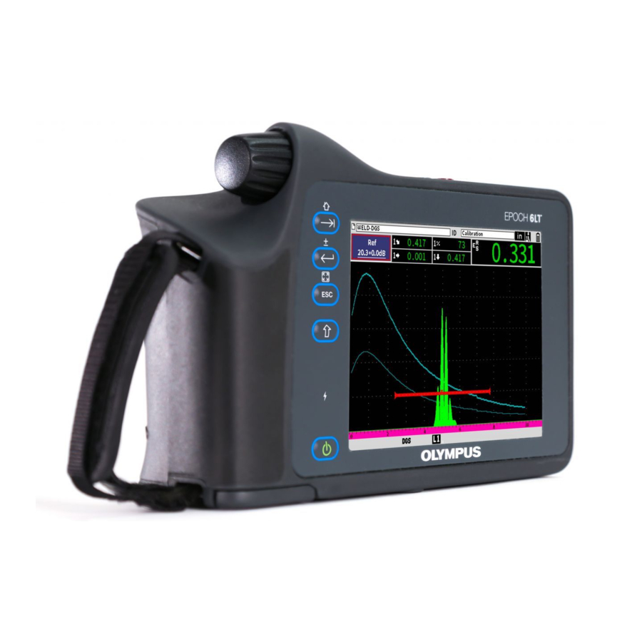
Olympus EPOCH 6LT User Interface Manual (232 pages)
Ultrasonic Flaw Detector
Brand:
Olympus
| Category:
Security Sensors
| Size: 2.04 MB
Table of Contents
Table of Contents
3
List of Abbreviations
9
Important Information - Please Read before Use
11
Intended Use
11
Instruction Manual
11
Safety Symbols
12
Safety Signal Words
12
Note Signal Words
13
Warranty Information
13
Technical Support
14
Introduction
15
1 Hardware User Interface Overview
17
Figure 1-1 EPOCH 6LT Front Panel
17
Enter Key
18
ESC Key
18
Shift Key
18
Tab Key
18
Adjustment Knob
19
Figure 1-2 Adjustment Knob
19
2 Software User Interface Overview
21
Figure 2-1 Live A-Scan Display Elements
21
Figure 2-2 File Identifier Bar with ID Example
22
Figure 2-3 Measurement Reading Boxes Example
22
File Identifier Bar
22
Gain Adjustment Box
22
Measurement Reading Boxes
22
Figure 2-4 Message Bar with a Message Example
23
Figure 2-5 Message Bar with Flags Displayed
23
Live A-Scan
23
Message Bar
23
Figure 2-6 Example of an A-Scan Waveform with Gates
24
Modes
24
Figure 2-7 Setup Menu (Left) and Sidebar Menu (Right)
25
Figure 2-8 Shortcut Menu
25
3 Setup Mode
27
Setup Menu
27
Figure 3-1 Setup Menu
27
Setup Menu Icons
28
Table 1 Setup Menu Icon Actions
28
Figure 3-2 Dialog Box (Left) and Setup Page (Right)
29
Navigating Dialog Boxes and Setup
29
Figure 3-3 Setup Page as Initially Displayed
30
4 Inspection Mode
33
Figure 4-1 Sidebar Menu
33
Sidebar Menu
34
Sidebar Menu Button Actions
34
Table 2 Button Types
34
Adjustable Value Buttons
35
Figure 4-2 Submenu with Highlighted Adjustable Value
35
Figure 4-3 Enhanced Border Indicates Selected Adjustable Value
35
Using the Sidebar Menu and Submenus
36
Figure 4-4 File Identifier Shortcut Menu
38
File Identifier Shortcut Menu
38
Shortcut Menus
38
Figure 4-5 Highlighted File Identifier Bar
39
Measurement Reading Shortcut Menu
39
Figure 4-6 Measurement Reading Shortcut Menu
40
Figure 4-7 Highlighted Measurement Reading Bar
40
Figure 4-8 Gain Adjustment Shortcut Menu
41
Figure 4-9 Highlighted Gain Adjustment Box
41
Gain Adjustment Shortcut Menu
41
5 Setup
43
Figure 5-1 Create Setup Page and Its Elements
43
Figure 5-2 Settings Menu
44
Opening a Setup Page
44
Using the Virtual Keypad
45
Figure 5-3 Edit Page with Virtual Keypad
46
File Management
47
Instrument Settings
47
User Keys Setup Page
47
Figure 5-4 Default Home Screen (Live A-Scan)
48
Figure 5-5 Custom User Key Setup Page
49
Figure 5-6 G1Start Selected as Home Location
50
Display Setup Page
51
Figure 5-7 Display Setup Page
51
Figure 5-8 X-Axis Grid Mode Options
53
Measurement Setup Page
54
Figure 5-9 Measurement Setup Page
55
Figure 5-10 Example of Measurement Reading Boxes with Icons
56
Table 3 Available Measurement Readings
56
Figure 5-11 Instrument Setup Page
60
Instrument Setup Page
60
Clock Setup Page
62
Figure 5-12 Clock Setup Page
62
Software Options Setup Page
62
Resets Setup Page
63
About Setup Page
64
Figure 5-13 Resets Setup Page
64
Instrument Info Setup
64
Wi-Fi Networks Setup Page
64
Upgrade Setup Page
65
Figure 5-14 Upgrade Setup Page
66
License Setup Page
66
Regulatory Setup Page
66
Diagnostic Test Setup Page
67
Legal Setup Page
67
Figure 5-15 Diagnostic Test Setup Page
68
6 Pulser/Receiver Adjustments
69
Adjusting the Gain (System Sensitivity)
69
Figure 6-1 Highlighted Gain Adjustment Box
69
Setting Reference Gain and Scanning Gain
70
Using the Auto XX% Feature
70
Selecting and Adjusting the Pulser
72
Figure 6-2 Scanning Gain Buttons
72
Energy (Voltage)
73
Figure 6-3 Pulser Dialog Box
73
Damping
74
Pulser Type
74
Pulser Frequency
75
Test Modes
75
Pulse Repetition Frequency (PRF)
76
Adjusting the Receiver
77
Digital Receiver Filters
78
Figure 6-4 Receiver Dialog Box
78
Reject Parameter
79
Waveform Rectification
79
Figure 6-5 Horizontal Line Indicating the Reject Level
80
7 Gates
81
Activating the Gates
81
Measurement Gates 1 and 2
82
Figure 7-1 Gate (G1) Status on
82
Quickly Adjusting Basic Gate Parameters
83
Figure 7-2 Gate 1 and Gate 2 (with Echo-To-Echo Turned On)
83
Figure 7-3 Gate 1 Submenu
84
Gate Measurement Modes
85
Figure 7-4 Gate1 Dialog Box
85
Figure 7-5 Gate Trigger Indicator in Edge (Left) and Peak (Right) Modes
86
Figure 7-6 Gate Trigger Indicator in 1Stpeak (Left) and J-Flank (Right) Modes
87
Viewing Measurement Readings
88
Gate Tracking and Echo-To-Echo Measurements
89
Time-Of-Flight Mode
90
Figure 7-7 Echo-To-Echo Measurement Example
90
Zooming in on a Gate
91
Figure 7-8 Time-Of-Flight Measurement
91
Gate Alarms
92
Threshold Alarms
92
Figure 7-9 Gate Tick Marks Indicating Alarm Threshold Type
93
Minimum Depth Alarm
93
Figure 7-10 Minimum Depth Alarm Marker
94
7.10 Peak Memory
95
Figure 7-11 Peak Memory Signal Envelope Example
95
7.11 Peak Hold
96
7.12 Freeze
97
8 Calibration
99
Basic Setup
99
Figure 8-1 UT Dialog Box
101
Calibration Modes
102
Figure 8-2 Angle Dialog Box
102
Straight Beam Modes
102
Angle Beam Modes
103
Calibration Procedure
103
Figure 8-3 Calibration - Dialog Box Initial Setup
105
Figure 8-4 Calibration - Ready to Auto 80% on Thin Echo
106
Figure 8-5 Calibration - Ready to Collect Thin Echo
107
Figure 8-6 Calibration - Ready to Collect Thick Echo
108
Figure 8-7 Calibration - Successfully Completed
109
9 Data Logger
111
Data File Types
112
Figure 9-1 Settings Menu
112
Incremental File Type
112
2-D Matrix Grid File Type
113
Calibration File Type
113
Data Logger Storage Capacity
113
Saving Data to Active Files
113
Data Logger Setup
114
Create
115
Figure 9-2 Create Setup Page
115
Figure 9-3 File Name Edit
116
File
117
Figure 9-4 File Setup Page
118
Figure 9-5 Name and ID of Open File on the Live A-Scan Display
119
Figure 9-6 Saved File Waveform
120
Figure 9-7 Saved File Data
121
Figure 9-8 Viewing All the Ids in a File
122
Figure 9-9 Saved File Waveform and Data
123
Figure 9-10 Recalled File Data
124
Figure 9-11 Details Setup Page
126
Figure 9-12 Summary Setup Page
127
Manage
127
Figure 9-13 Manage Setup Page
128
Figure 9-14 Edit Setup Page
129
Figure 9-15 Copy Setup Page
130
Figure 9-16 Delete Dialog Box
131
Figure 9-17 Clear Dialog Box
131
Figure 9-18 Select ID Setup Page
132
Memo
132
Figure 9-19 Memo Setup Page
133
Figure 9-20 Memo Dictionary Page
134
Figure 9-21 Memo Dictionary Page - Editing a Label
135
Figure 9-22 Memo Dictionary Page - Inserting Label Info
136
Backup|Restore
137
Figure 9-23 Memo Dictionary Page - Inserted Info
137
Figure 9-24 Backup|Restore Setup Page
138
Grid View
140
Activating the Grid View
140
Configuring the Grid
141
Figure 9-25 Grid Dialog Box
141
Using the Grid
142
Figure 9-26 Grid View on the Live A-Scan Display
143
Video Recorder
145
Activating the Video Recorder
145
Figure 9-27 Grid Controls in a Saved File
145
Figure 9-28 Video Sidebar Submenu
146
Recording and Saving Video
146
Figure 9-29 Recording in Progress
147
Figure 9-30 Create Video File Setup Page
148
Figure 9-31 Video Files Setup Page
149
Working with Video Files
149
Figure 9-32 Video Review Setup Page
150
Figure 9-33 Import (Video File) Setup Page
152
10 Wi-Fi Networks
155
10.1 Connecting to a Wireless LAN (Wi-Fi) Network
155
Figure 10-1 Wi-Fi Networks Setup Page
156
Figure 10-2 Wi-Fi Secure Logon Page
157
Figure 10-3 Wi-Fi Unsecured Logon Page
158
10.2 Adding a Wireless LAN (Wi-Fi) Network
159
Figure 10-4 Wi-Fi Connection Status Page
159
Figure 10-5 Add Network Setup Page
160
11 Software Features and Options
161
11.1 Defining Licensed and Unlicensed Software Features
161
11.2 Activating Software Options
162
Figure 11-1 Software Options Setup Page
162
11.3 Dynamic DAC/TCG
163
Enabling the DAC/TCG Feature
164
Applying Reference Correction
165
Building a DAC Curve in Standard or ASME III Mode
166
Figure 11-2 DAC/TCG Dialog Box
166
Figure 11-3 DAC/TCG Sidebar Submenu
167
Figure 11-4 First DAC Point
168
Figure 11-5 Second DAC Point
169
Figure 11-6 Completed DAC Curve
170
Figure 11-7 Partial DAC Curve with each Echo Set to 80 % FSH
171
DAC Inspection Mode
172
Figure 11-8 Completed DAC Curve
172
Figure 11-9 Completed DAC Curves in TCG View Mode
173
Figure 11-10 a Small Range DAC
174
Gain Adjustment Options
174
Figure 11-11 Standard DAC with 6 Db Scanning Gain
175
Figure 11-12 Standard DAC with Scanning Gain off
176
Figure 11-13 DAC with 6 Db Scan Gain - Reference Correction Active
177
Figure 11-14 DAC Curves with Adjusted Gain
178
Figure 11-15 JIS Mode
179
Jis Dac
179
Custom DAC Curves
180
Figure 11-16 JIS Curves
180
Figure 11-17 Custom DAC Setup
181
11.4 Dgs/Avg
182
Figure 11-18 Completed Custom DAC
182
Enabling the DGS/AVG Option
183
Figure 11-19 DGS/AVG Dialog Box
184
Figure 11-20 Reference Reflector before Capture
186
Curve-Adjustment Options
187
Figure 11-21 DGS/AVG Curves on the Screen
187
Transfer Correction
187
DGS/AVG Curve Gain
188
Figure 11-22 (Ref) Gain Adjustment Box
188
Figure 11-23 Gain Curve Adjusted DGS
189
Registration Level Adjustment
189
Relative Attenuation Measurement
190
11.5 AWS D1.1/D1.5 Weld Rating Software
191
Enabling the AWS D1.1 Option
192
Figure 11-24 AWS Dialog Box
192
Figure 11-25 Active AWS with a Ref Level of 50
193
Figure 11-26 AWS Ref B Value Dialog Box
194
Figure 11-27 Active AWS with D Rating
195
Scanning Gain
195
Calculating a and C Values
196
11.6 Back Wall Echo Attenuator
196
Enabling the BEA Option
197
Figure 11-28 Activating the BEA
198
Operating the BEA
198
11.7 Corrosion Module
199
Figure 11-29 Adjusting Back Wall Gain
199
Key Features
200
Corrosion Module Modes
201
Figure 11-30 Corrosion Module Grid View
201
Figure 11-31 Scanning Mode Screen
202
Figure 11-32 Precision Mode Screen
203
Corrosion Module Activation and Setup
204
Figure 11-33 Probe Detected Dialog Box
204
Figure 11-34 Corrosion Dialog Box
205
Figure 11-35 Transducer Setup Page
206
Figure 11-36 Do-Zero Dialog Box
206
Figure 11-37 Incorrectly Triggered Measurement
208
Figure 11-38 AGC off in Precision Mode
209
Figure 11-39 Adjust Gain Value in Precision Mode
210
Figure 11-40 Correctly Triggered Measurement
211
Figure 11-41 Corrosion Dialog Box
212
Figure 11-42 Receiver Dialog Box
213
Figure 11-43 Echo-To-Echo Measurement
214
Figure 11-44 Shear Wave Measurement Error
215
Figure 11-45 Corrosion Sidebar Menu (G2Start)
216
Table 4 Flag Descriptions
217
List of Figures
221
List of Tables
225
Index
227
Advertisement
Olympus EPOCH 6LT User Manual (66 pages)
Ultrasonic Flaw Detector
Brand:
Olympus
| Category:
Security Sensors
| Size: 1.39 MB
Table of Contents
Table of Contents
3
DMTA-10083-01EN, Rev. 3, June
6
List of Abbreviations
7
Figure I-1 Label Location
9
Labels and Symbols
9
Table 1 Contents of the Rating Label
10
Important Information - Please Read before Use
13
Intended Use
13
Instruction Manual
13
Instrument Compatibility
14
Repair and Modification
14
Safety Symbols
15
Safety Signal Words
15
Note Signal Words
16
Safety
16
Warnings
17
Battery Precautions
18
Equipment Disposal
19
CE (European Community)
19
WEEE Directive
19
China Rohs
19
Korea Communications Commission (KCC)
21
EMC Directive Compliance
21
FCC (USA) Compliance
21
ICES-001 (Canada) Compliance
22
Warranty Information
22
Technical Support
23
Introduction
25
1 Package Content
27
Unpacking the Instrument
27
Case Contents
27
EPOCH 6LT Flaw Detector Components
28
Table 2 EPOCH 6LT Ultrasonic Flaw Detector Components
28
DMTA-10083-01EN, Rev. 3, June
28
Standard Accessories
29
Battery
29
AC Charger/Adaptor
29
Figure 1-1 EPOCH 6LT Li-Ion Battery
29
Figure 1-2 AC Charger/Adaptor
30
Table 3 Region Specific Power Cord Options
30
USB Data Cable
31
USB Drive
31
Optional Accessories
31
Figure 1-3 USB Data Cable
31
Charging Base
32
Table 4 EPOCH 6LT Charging Base
32
Battery Conditioning
33
2 Overview
35
External Connectors
35
Figure 2-1 External Connectors
35
AC Adaptor Connector
36
LEMO Transducer Connectors
36
Battery Compartment
36
Figure 2-2 Color-Coded LEMO Connectors
36
Data Port
37
Figure 2-3 Battery Compartment-Cover Closed
37
Figure 2-4 Data Port Connectors and Reset Switch
37
Digital Video Connector
38
USB a Connector
38
Mini USB Connector
38
Reset Switch
38
Accessory Mount
38
Figure 2-5 Accessory Mount
38
Wrist Strap Mounts
39
Keys, Knob, and Indicators
39
Figure 2-6 Wrist Strap Mounts
39
Power Key
40
Power Indicator
40
Shift Key
40
Figure 2-7 EPOCH 6LT Front Panel
40
Escape Key
41
Enter Key
41
Tab Key
41
Adjustment Knob
41
Figure 2-8 Adjustment Knob
41
3 Operation
43
Turning on the Instrument
43
Turning off the Instrument
43
Connecting the AC Charger/Adaptor
44
Figure 3-1 Connecting the DC Power Plug
44
Opening the Data Port Cover
45
Figure 3-2 AC Charger/Adaptor
45
Figure 3-3 Data Port Cover Release Button
46
Figure 3-4 Data Port-Cover Open
46
4 Maintenance and Troubleshooting
47
Battery Replacement
47
Figure 4-1 Battery Compartment Cover Release Button
47
Figure 4-2 Battery Compartment-Cover Open
48
Figure 4-3 Battery Removal
49
Instrument Cleaning
50
Seal Verification
50
Display Protection
50
Annual Calibration
50
Troubleshooting
51
Table 5 Troubleshooting Guide
51
Appendix A: Specifications
53
Table 6 General Specifications
53
Table 7 Pulser
54
Table 8 Receiver
54
Table 9 Calibration
54
Table 10 Gates
55
Table 11 Measurements
55
Table 12 Environmental Ratings
56
Table 13 Instrument Inputs and Outputs
56
Appendix B: Parts List
57
Table 14 EPOCH 6LT Basic Kit
57
Table 15 EPOCH 6LT Optional Accessories
57
Table 16 Software Options
58
List of Figures
59
List of Tables
61
Index
63
Olympus EPOCH 6LT Getting Started Manual (8 pages)
Ultrasonic Flaw Detector
Brand:
Olympus
| Category:
Security Sensors
| Size: 0.37 MB
Table of Contents
Charging the Lithium-Ion Battery
3
To Replace the Battery
3
Battery Precautions
4
Electrical Warnings
5
Equipment Disposal
5
Advertisement
Advertisement
Related Products
Olympus EPOCH 600
Olympus EPOCH 1000 Series
Olympus BondMaster 600
Olympus Stylus 6000 White - Stylus 6000 10MP Digital Camera
Olympus 6MP
Olympus Stylus Tought 6020
Olympus EPOCH 650
Olympus nortec 600
Olympus Panametrics Epoch 4 Plus
Olympus Sonic 1200S/HR
Olympus Categories
Digital Camera
Voice Recorder
Microscope
Camera Accessories
Camera Lens
More Olympus Manuals
Login
Sign In
OR
Sign in with Facebook
Sign in with Google
Upload manual
Upload from disk
Upload from URL