Table of Contents
Advertisement
Quick Links
NORTEC 600
Eddy Current Flaw Detector
User's Manual
This instruction manual contains essential information on how to use this Olympus product safely and effectively.
Before using this product, thoroughly review this instruction manual. Use the product as instructed.
Keep this instruction manual in a safe, accessible location.
DMTA-10040-01EN — Rev. E
February 2018
Advertisement
Chapters
Table of Contents

Related Manuals for Olympus nortec 600


Summary of Contents for Olympus nortec 600
- Page 1 DMTA-10040-01EN — Rev. E February 2018 This instruction manual contains essential information on how to use this Olympus product safely and effectively. Before using this product, thoroughly review this instruction manual. Use the product as instructed. Keep this instruction manual in a safe, accessible location.
- Page 2 Olympus Scientific Solutions Americas, 48 Woerd Avenue, Waltham, MA 02453, USA Copyright © 2014, 2015, 2017, 2018 by Olympus. All rights reserved. No part of this publication may be reproduced, translated, or distributed without the express written permission of Olympus.
-
Page 3: Table Of Contents
DMTA-10040-01EN, Rev. E, February 2018 Table of Contents List of Abbreviations ..................ix Labels and Symbols ................... 1 Important Information — Please Read Before Use ........7 Intended Use .......................... 7 Instruction Manual ........................ 7 Instrument Compatibility ..................... 8 Repair and Modification ....................... 9 Patent Rights Protection ....................... - Page 4 Battery Compartment ..................30 1.4.3 Lithium-Ion Battery ..................31 1.4.4 Alkaline Batteries ................... 32 Optional microSD Card Installation ............... 33 NORTEC 600 Hardware Features ................34 1.6.1 Hardware Overview ..................35 1.6.1.1 Front Panel and SmartKnob ............... 36 1.6.1.2 Keypad ....................37 1.6.2...
- Page 5 Display Menu in Dual Frequency — DISP Key ........116 4.4.7 ALARM Menu in Dual Frequency — ALARM Key ....... 118 5. Using the Instrument ................119 Common NORTEC 600 Applications ..............120 5.1.1 Detecting Surface-Breaking Cracks — General Purpose Procedure for All NORTEC 600 Models .................. 120...
- Page 6 (Indexing) Scanner — NORTEC 600S and NORTEC 600D Models ..166 Special and Educational Applications ..............173 5.2.1 Using the Impedance Plane Theory and Display — All NORTEC 600 Models ......................174 5.2.2 Sorting Metals by Evaluating Conductivity — All NORTEC 600 Models ......................
- Page 7 Upgrading the Instrument Software without NORTEC PC ......305 Creating a PDF ......................307 Issuing Remote Commands to the NORTEC 600 from a PC ......308 Remotely Controlling the NORTEC 600 from a PC ........... 318 Managing Files on the NORTEC 600 from your PC .......... 320 Unlocking NORTEC 600 Upgrade Options with your PC .......
-
Page 8: Dmta-10040-01En, Rev. E, February
DMTA-10040-01EN, Rev. E, February 2018 viii Table of Contents... -
Page 9: List Of Abbreviations
DMTA-10040-01EN, Rev. E, February 2018 List of Abbreviations air conditioner alternating current CD-ROM compact disc read-only memory direct current eddy current testing EFUP environment-friendly use period gigabyte input-output identification internal diameter ingress protection liquid crystal display light-emitting diode Li-ion lithium-ion military one-thousandths of one inch (0.0254 mm) not applicable... - Page 10 DMTA-10040-01EN, Rev. E, February 2018 statistical process control universal serial bus video graphics array WEEE waste electrical and electronic equipment wall thickness List of Abbreviations...
-
Page 11: Labels And Symbols
Safety-related labels and symbols are attached to the instrument at the locations shown in Figure i-1 on page 1. If any or all of the labels or symbols are missing or illegible, please contact Olympus. Instruction and rating label (see Table 1 on page 2) Figure i‑1 Label attached to the back of the instrument... -
Page 12: Figure I-2 Location Of The Serial Number
DMTA-10040-01EN, Rev. E, February 2018 Serial number location (see Table 1 on page 2) Figure i‑2 Location of the serial number Table 1 Content of the rating label Content This symbol indicates the location of the membrane vent. The direct current symbol. Efficiency of battery chargers specific to California, USA. - Page 13 The EFUP for the NORTEC 600 has been determined to be 15 years. Note: The Environment-Friendly Use Period (EFUP) is not meant to be interpreted as the period assuring functionality and product performance.
-
Page 14: Table 2 Content Of The Probe Adaptor Labels
DMTA-10040-01EN, Rev. E, February 2018 Table 1 Content of the rating label (continued) SERIAL The serial number is a nine (9) digit number in the following format: yynnnddmm where: Production year Unit number manufactured that day Production day Production month For example, the 130050609 serial number indicates that the fifth unit (005) was produced on 6 September 2013. - Page 15 The EFUP for the NORTEC 600 probe cable has been determined to be 15 years. Note: The Environment-Friendly Use Period (EFUP) is not meant to be interpreted as the period assuring functionality and product performance.
- Page 16 DMTA-10040-01EN, Rev. E, February 2018 Labels and Symbols...
-
Page 17: Important Information - Please Read Before Use
The NORTEC 600 is designed to perform nondestructive inspections on industrial and commercial materials. WARNING Do not use the NORTEC 600 for any purpose other than its intended use. It must never be used to inspect or examine human or animal body parts. Instruction Manual This instruction manual contains essential information on how to use this Olympus product safely and effectively. -
Page 18: Instrument Compatibility
Some of the details of components illustrated in this manual may differ from the components installed on your instrument. However, the operating principles remain the same. Instrument Compatibility Only use the NORTEC 600 instrument with the following ancillary equipment: • Rechargeable lithium-ion (Li-ion) battery pack (Olympus P/N: 600-BAT-L-2 [U8760058]) •... -
Page 19: Repair And Modification
DMTA-10040-01EN, Rev. E, February 2018 • RA-2000 (replaces the RA-19 scanner, which became obsoleted in 2002. The RA-19 scanner is NOT compatible with the NORTEC 500 or NORTEC 600 instrument series) • • GE Hocking MiniDrive • Rohmann Elotest MR3 scanner... -
Page 20: Safety Symbols
DMTA-10040-01EN, Rev. E, February 2018 Safety Symbols The following safety symbols might appear on the instrument and in the instruction manual: General warning symbol This symbol is used to alert the user to potential hazards. All safety messages that follow this symbol shall be obeyed to avoid possible harm or material damage. Shock hazard caution symbol This symbol is used to alert the user to potential laser hazards. -
Page 21: Note Signal Words
DMTA-10040-01EN, Rev. E, February 2018 CAUTION The CAUTION signal word indicates a potentially hazardous situation. It calls attention to a procedure, practice, or the like that if not correctly performed or adhered to may result in minor or moderate personal injury, material damage, particularly to the product, destruction of part or all of the product, or loss of data. -
Page 22: Warnings
For any problem or question regarding this instrument, contact Olympus or an authorized Olympus representative. • Do not touch the connectors directly by hand. Otherwise, a malfunction or electric shock may result. -
Page 23: Battery Precautions
Do not expose a battery to moisture or rain; doing so could cause an electric shock. • Only use the NORTEC 600 unit or an external charger approved by Olympus to charge the batteries. • Only use batteries supplied by Olympus. -
Page 24: Equipment Disposal
IMPORTANT Tubing probes (with cables) that are 25 m (82 ft) in length or under are CE compliant when used with the NORTEC 600 instrument. Probes (with cables) over 25 m (82 ft) in length are not CE compliant. WEEE Directive... -
Page 25: China Rohs
The EFUP for the NORTEC 600 has been determined to be 15 years. Note: The Environment-Friendly Use Period (EFUP) is not meant to be interpreted as the period assuring functionality and product performance. -
Page 26: Korea Communications Commission (Kcc)
This equipment generates and uses radio-frequency energy and, if not installed and used properly (that is, in strict accordance with the manufacturer’s instructions), may cause interference. The NORTEC 600 has been tested and found to comply with the limits for an industrial device in accordance with the specifications of the EMC directive. -
Page 27: Ices-001 (Canada) Compliance
Retain packing materials, waybills, and other shipping documentation needed in order to file a damage claim. After notifying the carrier, contact Olympus for assistance with the damage claim and equipment replacement, if necessary. -
Page 28: Technical Support
Technical Support Olympus is firmly committed to providing the highest level of customer service and product support. If you experience any difficulties when using our product, or if it fails to operate as described in the documentation, first consult the user’s manual, and then, if you are still in need of assistance, contact our After-Sales Service. -
Page 29: Introduction
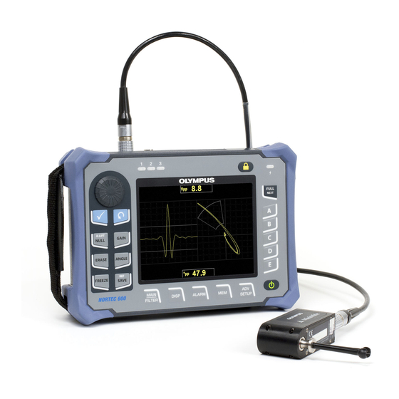
DMTA-10040-01EN, Rev. E, February 2018 Introduction This user’s manual provides operating instructions for the Olympus NORTEC 600 instrument, which uses eddy currents to detect surface flaws in various types of metals (see Figure i-3 on page 19). The information in this manual is organized to explain the technology, safety details, hardware, and software. -
Page 30: Dmta-10040-01En, Rev. E, February
DMTA-10040-01EN, Rev. E, February 2018 Introduction... -
Page 31: Instrument Overview
DMTA-10040-01EN, Rev. E, February 2018 1. Instrument Overview This chapter provides a brief overview of the Olympus NORTEC 600 eddy current flaw detector, and includes the principle of operation, accessories, and all common operational requirements. Operating Principle The NORTEC 600 is a small, lightweight flaw detector designed to make fast, accurate, and repeatable measurements on conductive materials such as aluminum, copper, stainless steel, steel, and titanium. -
Page 32: Contents Of The Case
DMTA-10040-01EN, Rev. E, February 2018 Contents of the Case The NORTEC 600 comes with several key accessories (see Figure 1-1 on page 23): • ISO-15548 certificate or calibration certificate (short form of the ISO-15548) (Olympus P/N: 7922035 [U8030145]). • Charger/adaptor (Olympus P/N: EP-MCA-X), where “X” denotes the AC power cord type (see Table 14 on page 343). -
Page 33: Connectors
A list of optional accessories available from Olympus can be found in “Accessories, Replacement Parts, and Upgrades” on page 341. Connectors Figure 1-2 on page 24 illustrates the connections of the NORTEC 600 instrument with the charger/adaptor, the microSD card, and a PC. Instrument Overview... -
Page 34: Figure 1-2 The Nortec 600 Connections
Using an unauthorized power cord may result in damage to instruments or serious injury to the user. The DC power, PROBE, and BNC connectors are located on the top end of the NORTEC 600 (see Figure 1-3 on page 24). DC power connector PROBE connector... -
Page 35: Figure 1-4 The Connectors Behind The Input/Output (I/O) Door
DMTA-10040-01EN, Rev. E, February 2018 CAUTION Do not allow metallic or foreign objects to enter the device through connectors or any other openings. Otherwise, an electric shock or malfunction may result. The USB port and the removable microSD memory card slot are located on the right- hand side of the instrument, hidden behind the input/output (I/O) door (see Figure 1-4 on page 25). -
Page 36: Power Requirements
Internal alkaline battery holder Press the power button ( ) to turn on the NORTEC 600 (see Figure 1-6 on page 27). Pressing this button once causes an initial beep, which is followed by the instrument startup screen, and then a second beep approximately five seconds later. -
Page 37: Charger/Adaptor
DMTA-10040-01EN, Rev. E, February 2018 Charger/adaptor indicator light Power button Figure 1‑6 Location of the NORTEC 600 power button and indicator light 1.4.1 Charger/Adaptor A NORTEC 600 charger/adaptor is provided with every instrument. This charger/adaptor is the primary method for powering the NORTEC 600, with or without a battery installed. -
Page 38: Figure 1-8 Connecting The Charger/Adaptor
DMTA-10040-01EN, Rev. E, February 2018 WARNING The NORTEC 600 charger/adaptor (P/N: EP-MCA-X) is designed to power the NORTEC 600 and charge the lithium-ion battery only (P/N: 600-BAT-L-2 [U8760058]). Do not attempt to charge any other types of batteries, including alkaline batteries in the battery holder (P/N: 600-BAT-AA [U8780295]), and do not attempt to use any other charger/adaptor. -
Page 39: Figure 1-9 Connecting The Dc Power Cable
DMTA-10040-01EN, Rev. E, February 2018 Lift the rubber seal that covers the DC connector on top of the NORTEC 600. Connect the DC output power cable from the charger/adaptor to the DC power connector on top of the NORTEC 600 (see Figure 1-9 on page 29). -
Page 40: Battery Compartment
1.4.2 Battery Compartment The NORTEC 600 battery compartment cover allows you to quickly access the battery (or AA batteries in the alkaline battery holder) without the need for tools. Two thumb screws on the battery compartment cover secure it to the instrument case and ensure the compartment is sealed. -
Page 41: Lithium-Ion Battery
(Olympus P/N: 600-BAT-AA [U8780295]) for extended portable use. WARNING If the NORTEC 600 is to be used with a rechargeable battery, only use the Olympus battery, P/N: 600-BAT-L-2 [U8760058]. Using any other type of battery might cause an explosion and injury. -
Page 42: Alkaline Batteries
Figure 1‑11 Removing the lithium‑ion battery 1.4.4 Alkaline Batteries The NORTEC 600 includes a battery holder (Olympus P/N: 600-BAT-AA [U8780295]). This holder accommodates eight AA-size alkaline batteries for situations where an AC power source is not available and the internal Li-ion battery is discharged. When operated under typical inspection conditions, the alkaline batteries typically provide three hours of continuous operation. -
Page 43: Optional Microsd Card Installation
ALK. The charger/adaptor does not recharge the batteries installed in the alkaline battery holder. Optional microSD Card Installation A 2 GB microSD card (Olympus P/N: MICROSD-ADP-2GB [U8779307]) can be installed in the NORTEC 600 instrument. To install the microSD removable memory card Remove the card from its packaging. -
Page 44: Nortec 600 Hardware Features
DMTA-10040-01EN, Rev. E, February 2018 Loosen the two thumb screws, and then open the NORTEC 600 I/O door (see Figure 1-13 on page 34). Thumb screws (two) microSD card slot microSD card USB port Figure 1‑13 Installing the microSD card Hold the card so that the microSD label faces toward the rear of the instrument. -
Page 45: Hardware Overview
Figure 1-14 on page 35 and Figure 1-15 on page 36 show the main components on the NORTEC 600 instrument. Protective rubber bumpers D-rings to attach the optional chest harness (at the four corners) Knob (SmartKnob) Display window (screen) Keypad Figure 1‑14 Overview of the NORTEC 600 hardware — Front view Instrument Overview... -
Page 46: Front Panel And Smartknob
1.6.1.1 Front Panel and SmartKnob The SmartKnob is an important feature of the NORTEC 600 instrument, and it is the primary method used to change different parameters within a menu. In this manual, the term “knob” is also used to refer to the SmartKnob. -
Page 47: Keypad
1.6.1.2 Keypad The NORTEC 600 is available with an English, Chinese, Japanese, or international keypad configuration (see Figure 1-17 on page 38 to Figure 1-20 on page 39, and Table 4 on page 40). The text labels on some keys may be replaced by pictograms, depending on the keypad configuration. -
Page 48: Figure 1-17 The Nortec 600 English Keypad
DMTA-10040-01EN, Rev. E, February 2018 Figure 1‑17 The NORTEC 600 English keypad Figure 1‑18 The NORTEC 600 Chinese keypad Chapter 1... -
Page 49: Figure 1-19 The Nortec 600 Japanese Keypad
DMTA-10040-01EN, Rev. E, February 2018 Figure 1‑19 The NORTEC 600 Japanese keypad Figure 1‑20 The NORTEC 600 international keypad Instrument Overview... -
Page 50: Table 4 Keypad Functions
FREEZE Direct-function key used to freeze the image displayed on the instrument for further evaluation. When the image is frozen, the NORTEC 600 also allows calibrating the eddy current signals, and changing the gains or angle. REF SAVE Direct-function key used to save images and settings in the instrument’s memory. - Page 51 DMTA-10040-01EN, Rev. E, February 2018 Table 4 Keypad functions (continued) International Function keypad Function description name symbol MAIN FILTER Provides access to the main menu, which controls functions such as frequency, gain, angle, and filters. DISP Provides access to the display menu, which controls functions such as display mode, position, trace, and grid.
-
Page 52: Connectors
1.6.2.1 Probe and BNC Connectors The NORTEC 600 instrument is supplied with a 16-pin LEMO (PROBE) connector and a BNC connector. The PROBE (LEMO) and BNC connectors are located at the top of the instrument, on the left-hand side. The two connectors are easily accessible from the front of the instrument (see Figure 1-21 on page 42). -
Page 53: Figure 1-22 The Vga Out And I/O Connectors
The I/O connector is used to connect an external horn or, if necessary, to connect an external control for integrating the NORTEC 600 into a system. For PC communication details, see “microSD and USB Port” on page 44. -
Page 54: Microsd And Usb Port
The NORTEC 600 allows the user to connect the instrument to a PC via the USB port. PC communication requires the interface program (Olympus P/N: N600-CD [U8030151]) provided with the instrument for file transfers. The NORTEC 600 can also communicate directly with other SPC programs. -
Page 55: Various Hardware Features
To prevent connector corrosion and damage to the instrument, keep the I/O door closed and sealed when no cable is connected. 1.6.3 Various Hardware Features The NORTEC 600 instrument’s physical features make it suitable for a variety of operating environments. 1.6.3.1 Instrument Stand The NORTEC 600 features an articulating stand for variable viewing angles (see Figure 1-24 on page 45). -
Page 56: O-Ring Gasket And Membrane Seals
1.6.4 Environmental Ratings The NORTEC 600 is an extremely rugged and durable instrument that can be used in harsh environments. To classify the instrument’s durability in wet or damp environments, Olympus has adopted the IP (ingress protection) system to rate how well the instrument is sealed. - Page 57 You must use sound judgment and take proper precautions before exposing the instrument to harsh environments. The NORTEC 600 adheres to the environmental standards listed in Table 8 on page 333. Instrument Overview...
- Page 58 DMTA-10040-01EN, Rev. E, February 2018 Chapter 1...
-
Page 59: Software User Interface
Figure 2‑1 The instrument label showing keypad functions Starting Up the Instrument When power is turned on, the NORTEC 600 starts up in one of two modes, depending on what is connected to the instrument. If no probe is connected, or if a probe that is not a PowerLink type of probe is connected, the first screen displayed by the NORTEC 600 software is the application quick-setup menu (see Figure 2-2 on page 50). -
Page 60: Navigating The Application Menu
) to go back to the NORTEC 600 main screen. Alternatively, if a PowerLink probe is connected to the instrument when it is turned on, the NORTEC 600 starts up in the PowerLink recognition screen (see Figure 2-3 on page 51). -
Page 61: Main Inspection Screen
DMTA-10040-01EN, Rev. E, February 2018 Figure 2‑3 The PowerLink recognition screen To navigate the application menu for PowerLink In the PowerLink recognition screen, load the program stored in the PowerLink probe by pressing the A key. You can use the KEEP LAST SETTINGS function to load the previous parameters if they are compatible with the probe or accessory that is detected. -
Page 62: Figure 2-4 The Main Inspection Screen
DMTA-10040-01EN, Rev. E, February 2018 Figure 2‑4 The main inspection screen The battery power indicator remains visible at the top of the screen, except when in full-screen mode (see Table 3 on page 29 for details). The time and date also remain visible, except when in full-screen mode. -
Page 63: Figure 2-5 The Nortec 600 Front Panel And Main Inspection Screen
Direct-function keys Menu keys Figure 2‑5 The NORTEC 600 front panel and main inspection screen The real-time readings bar displays user-configurable readings (measurements) [see Figure 2-5 on page 53]. It can display a maximum of two real-time readings from among the available choices. The real-time readings bar can be set to display one or two readings, or it can be disabled. -
Page 64: Selecting From The Menus
DMTA-10040-01EN, Rev. E, February 2018 Selecting from the Menus The NORTEC 600 menu keys at the bottom of the front panel are MAIN FILTER ), DISP ( ), ALARM ( ), MEM ( ), and ADV SETUP ( ). These keys provide access to the operation menu. -
Page 65: Using The All Settings Menu
DMTA-10040-01EN, Rev. E, February 2018 Parameters Title bar Help text Figure 2‑6 The ALL SETTINGS menu 2.3.1 Using the ALL SETTINGS Menu The ALL SETTINGS menu is accessed through the ADV SETUP menu key ( To use the ALL SETTINGS menu Press the ADV SETUP menu key ( Press the B key. -
Page 66: Special Functions In The All Settings Menu
“Using the ALL SETTINGS Menu” on page 55. NOTE If the NORTEC 600 instrument is being used in noisy conditions, an external horn can be used. The horn connects to the I/O connector on the back of the instrument and increases the audible alarm’s sound output to 70 dB (see Table 12 on page 342 for the... -
Page 67: Figure 2-7 Example Of Vpp And Deg Pp
DMTA-10040-01EN, Rev. E, February 2018 • HPP — Maximum horizontal voltage, peak-to-peak • VMAX — Maximum vertical voltage from extended null line • HMAX — Maximum horizontal voltage from extended null line • DEG PP — Angle of VMAX, peak-to-peak Volts P-P Angle P-P Figure 2‑7 Example of VPP and DEG PP... -
Page 68: Figure 2-9 Example Of Vpp
DMTA-10040-01EN, Rev. E, February 2018 Volts P-P Vert. Figure 2‑9 Example of VPP Volts Max Horz. (+ or −) Figure 2‑10 Example of HMAX Chapter 2... -
Page 69: Enabling Real-Time Readings On The Main Inspection Screen
DMTA-10040-01EN, Rev. E, February 2018 Volts Max Vert. (+ or −) Figure 2‑11 Example of VMAX 2.4.1 Enabling Real-Time Readings on the Main Inspection Screen The real-time readings are enabled through the ADV SETUP menu key ( To enable the real-time readings bar on the main inspection screen Press the ADV SETUP menu key ( Press the B key. -
Page 70: Enabling The Real-Time Readings In Full-Screen Mode - Full Next Key
DMTA-10040-01EN, Rev. E, February 2018 Press the Return key ( ) to exit. 2.4.2 Enabling the Real-Time Readings in Full-Screen Mode — FULL NEXT The real-time readings are also available in full-screen mode, which can be accessed using the FULL NEXT key ( ) shown in Figure 2-5 on page 53. - Page 71 DMTA-10040-01EN, Rev. E, February 2018 Press the Return key ( ) to exit. Software User Interface...
- Page 72 DMTA-10040-01EN, Rev. E, February 2018 Chapter 2...
-
Page 73: Initial Setup
This chapter contains the basic configurations for the NORTEC 600 instrument. Setting the User Interface Language and the Decimal Symbol You can configure the NORTEC 600 instrument to present the user interface in the following languages: English, French, Spanish, German, Japanese, Chinese, Russian, Swedish, Italian, Portuguese, Norwegian, Hungarian, Polish, Dutch, and Czech. -
Page 74: Setting The Clock
Setting the Clock The NORTEC 600 has a built-in date and time clock. You can set the date and the time, and select their respective format. The NORTEC 600 saves all inspection results with their acquisition date. -
Page 75: Changing The Display Settings
DMTA-10040-01EN, Rev. E, February 2018 To change the location of saved files Press the ADV SETUP menu key ( ) twice, and then press the B key to access the SYSTEM SETUP screen (see Figure 3-1 on page 63). Repeatedly press the FULL NEXT key ( ) until FILE SAVE LOCATION is highlighted. -
Page 76: Changing The Display Brightness
Choosing a high percentage increases the brightness of the display. By default, the display brightness is set to 100 %. The NORTEC 600 uses a transflective color display that reflects ambient light and becomes brighter in direct light. With brighter ambient conditions, you can set the display BRIGHTNESS to a lower percentage. -
Page 77: Adjusting Auto Erase
BRIGHTNESS set to 50 %. Adjusting Auto Erase You can adjust the NORTEC 600 to clear (erase) the screen contents automatically after the NULL key is pressed. By default, the AUTO ERASE function is set to ON, but it can be disabled by selecting OFF. -
Page 78: Enabling Knobless Entry For Harsh Environments
Enabling Knobless Entry for Harsh Environments The knobless function allows the NORTEC 600 to be used in radioactive or harsh environments where the instrument has to be put inside a bag, which makes it difficult to use the knob. -
Page 79: Control Functions
DMTA-10040-01EN, Rev. E, February 2018 4. Control Functions This chapter provides explanations of the NORTEC 600 instrument control functions. PowerLink The PowerLink feature enables the NORTEC 600 eddy current instrument to automatically recognize Olympus PowerLink probes and rotating scanners when they are connected to the instrument. -
Page 80: Instrument Controls
At this point, if the PowerLink function has been enabled, the settings from the probe or rotating scanner will be loaded into the NORTEC 600 instrument. If the PowerLink function has been disabled, this screen will be bypassed. In either case, the instrument will next proceed to the main inspection screen. -
Page 81: Display
4.2.1 Display The NORTEC 600 instrument is configured with a color liquid crystal display (LCD) and offers 640 × 480 resolution (full VGA). The LCD display, also referred to as a screen, shows the eddy current signal, menus, status bar, messages, and full screen text when required. - Page 82 To enable A-LIFT (Auto Liftoff) NOTE The steps that follow assume that the following criteria have been met: • A probe is connected to the NORTEC 600 instrument. • The probe has been “nulled” normally. • The liftoff is not horizontal (see Figure 4-3 on page 73).
-
Page 83: Figure 4-3 Probe Liftoff-Initially Not Horizontal
DMTA-10040-01EN, Rev. E, February 2018 Figure 4‑3 Probe liftoff—initially not horizontal Figure 4‑4 The LIFT PROBE message after holding the A‑LIFT NULL key Control Functions... -
Page 84: Figure 4-5 Probe Liftoff After Nulling
DMTA-10040-01EN, Rev. E, February 2018 Figure 4‑5 Probe liftoff after nulling ERASE ( Provides the ability to erase the instrument screen instantly; this key does not have a secondary function. FREEZE ( The primary function of the FREEZE key ( ) is to freeze the current image on the instrument screen for further evaluation. -
Page 85: Figure 4-6 Freezing The Current Image On The Instrument Screen
DMTA-10040-01EN, Rev. E, February 2018 Figure 4‑6 Freezing the current image on the instrument screen The secondary function of the FREEZE key ( ) is to allow adjustment or manipulation of the frozen screen image. This is useful when calibrating for the inspection being performed. - Page 86 DMTA-10040-01EN, Rev. E, February 2018 GAIN ( Used to adjust the instrument’s gain settings. Pressing this key provides direct access to the instrument’s gain settings while any instrument settings are displayed in the instrument settings menu (see Figure 2-5 on page 53). Pressing the GAIN key ( ) will display the instrument gain settings in the quick-access bar shown in Figure 2-5 on page 53.
-
Page 87: Menu Keys
DMTA-10040-01EN, Rev. E, February 2018 To turn off any reference signal displayed in the background, simply press and hold the REF SAVE direct-function key ( ) until the signal disappears. 4.2.4 Menu Keys The menu keys located at the bottom of the instrument are used to select operation menus. -
Page 88: Knob
4.2.6 Hidden Function — Screen Capture On the NORTEC 600 instrument, you can send a screen-capture image file to the removable (external) microSD card by holding the MAIN FILTER menu key ( and then pressing and holding the REF SAVE key ( ) until you hear a beep, after which you release the keys. -
Page 89: Ambidextrous Controls
DMTA-10040-01EN, Rev. E, February 2018 NOTE • Only the gain, angle, and frequency are controlled by knobless entry. • The following steps assume that the MAIN FILTER menu key ( ) has been pressed. To use knobless entry Enable the knobless function in the SYSTEM SETUP screen (see “Enabling Knobless Entry for Harsh Environments”... -
Page 90: Full Next Key
DMTA-10040-01EN, Rev. E, February 2018 Figure 4‑8 The SYSTEM SETUP screen Repeatedly press the FULL NEXT key ( ) until AMBIDEXTROUS is selected. Rotate the knob to select ON, and then press the MAIN FILTER menu key ( to display the controls on the right side of the instrument (see Figure 4-9 on page 80). -
Page 91: Figure 4-10 The Settings Display (Left) And Maximized Display (Right)
This permits full use of the NORTEC 600 display for inspections (see Figure 4-10 on page 81). The instrument’s settings can be displayed again by pressing the FULL NEXT key ( ), or any other function or menu key. -
Page 92: Menus
DMTA-10040-01EN, Rev. E, February 2018 Menus The NORTEC 600 menus described in this section are opened by pressing the corresponding menu keys, which are described in “Menu Keys” on page 77. 4.3.1 Frequency (FREQ 1) Menu — MAIN FILTER Key... - Page 93 DMTA-10040-01EN, Rev. E, February 2018 To enable the fine-knob function, press the Enter key ( ) when ANGLE is highlighted. The fine-knob function can be used to adjust the angle more precisely. ANGLE will be underlined when this function is enabled. The angle can then be changed in 0.1 degree increments.
-
Page 94: Filter Menu - Main Filter Key
DMTA-10040-01EN, Rev. E, February 2018 when this function is enabled. The gain can then be changed in 1.0 dB increments. To turn off the coarse-knob function, press one more time, which returns the gain adjustments to 0.1 dB increments. 4.3.2 Filter Menu —... -
Page 95: Special Menu - Main Filter Key
Special Menu — MAIN FILTER Key PRB DRV (probe drive) The NORTEC 600 instrument has three levels of probe drive that can be selected: LOW, MEDIUM, and HIGH. The approximate peak-to-peak voltages are 2 V, 6 V, and 12 V, respectively. - Page 96 “Heat Exchanger Tubing Applications” on page 228). Slide Rule The NORTEC 600 instrument includes a useful slide-rule tool for determining the standard depth of penetration for a given material at a specified frequency. The user can select a material from the list or enter a specific conductivity value.
-
Page 97: Display Menu - Disp Key
The display menu contains submenus to control various functions such as horizontal and vertical position, display erase, trace, grid, and zoom. DSP MODE (display mode) Six display modes are available on the NORTEC 600 instrument: IMP (impedance), SWP+IMP (sweep plus impedance), SWEEP, WATERFALL, DUAL IMP (dual impedance), and ALL IN ONE. - Page 98 DISP Key” on page 116. POSITION Used to select the NORTEC 600 instrument‘s null position. By default, the null position is set at the center of the instrument screen. There are five preset null positions, as well as a modifiable position named CUSTOM.
- Page 99 DMTA-10040-01EN, Rev. E, February 2018 TOP LEFT Places the null position near the top left, at 20 % horizontal and 80 % vertical. CUSTOM Places the null position at a user-determined point, between 0 % and 100 % horizontal and between 0 % and 100 % vertical. Press H POS (horizontal position) or V POS (vertical position) to create a custom null position.
- Page 100 If this is the case, it is recommended to use display erase instead. CURSOR Adjusts the display of the eddy current signal trace on the NORTEC 600 screen by changing the shape of the signal focal spot. Two settings are available: DOT and BOX.
-
Page 101: Alarm Menu - Alarm Key
Provides a polar grid. ZOOM Adjusts the viewable portion of the NORTEC 600 screen. The null-point area of the instrument screen is magnified by applying a horizontal and vertical digital gain of 10. In ZOOM mode, all display functions are disabled, with the exception of ZOOM OFF or ON. -
Page 102: Memory Menu - Mem Key
The NORTEC 600 is capable of storing and retrieving complete instrument setups. By default, the data is saved with the date, time, and instrument-generated file name. If a PowerLink probe remains connected when the data is stored, the probe part number and description are also recorded. -
Page 103: Figure 4-13 The Show Readings Function
DMTA-10040-01EN, Rev. E, February 2018 Figure 4‑13 The SHOW READINGS function Figure 4‑14 The HIDE READINGS function RECALL Resets the instrument and loads the instrument settings associated with the data file that is recalled. To recall a stored data file, press the MEM menu key ( ), rotate the knob until the desired data file is highlighted, and then press the B key. - Page 104 DMTA-10040-01EN, Rev. E, February 2018 EDIT Enables editing of the file name and adding user FILE NOTES (text) to the stored data. To edit text (FILE NAME or FILE NOTE) of a stored data file, press the MEM menu key ( ), rotate the knob until the desired data file is highlighted, and then press the C key;...
-
Page 105: Figure 4-15 The Store Function
Used to create a backup copy of the instrument data, which is then saved on the external microSD card. This image can then be transferred to a computer or to another NORTEC 600 instrument. If the external microSD card contains data, this function acts as a RESTORE: the SD card’s data contents are copied to replace the instrument’s internal memory. -
Page 106: Memory Text Editor
DMTA-10040-01EN, Rev. E, February 2018 USER INFO Allows you to enter information on the user, job, company, work order, instrument serial number, etc. The information in USER INFO can easily be transferred into the NORTEC PC software and used as a header for reports. CAPTURE MODE In all modes except conductivity, CAPTURE MODE defines the action performed by the instrument when the REF SAVE key (... -
Page 107: Figure 4-16 The File Manager Menu's Memory Text Editor And Special Buttons
DMTA-10040-01EN, Rev. E, February 2018 Press the FULL NEXT key ( ) to navigate to the desired field to be edited: FILE NAME and/or FILE NOTE. Press the C key. The memory text editor is activated on the instrument display (see Figure 4-16 on page 97). - Page 108 DMTA-10040-01EN, Rev. E, February 2018 The navigation keys or special buttons in the text editor allow you to modify characters that have been mistakenly chosen, or modify previously entered information, without the need to retype the entire field (see Figure 4-16 on page 97, which identifies the special buttons and characters).
-
Page 109: Advanced Setup Menu - Adv Setup Menu Key
For further details, see also “Common NORTEC 600 Applications” on page 120. To select an application, press the ADV SETUP menu key ( ), followed by the A key. -
Page 110: Figure 4-17 The Application Selection Menu
The eight available applications allow you to quickly set up the instrument for commonly used eddy current inspections. NOTE The NORTEC 600 applications are designed for quick setup of the instrument. However, always follow published maintenance procedures when inspecting. ALL SETTINGS The ALL SETTINGS menu gives you access to all instrument menus. -
Page 111: Figure 4-18 The All Settings Menu (First Of Two Screens)
NOTE The NORTEC 600 instrument does not use an enter key to save the selection made on any of its menus. Instead, the selected (displayed) value is automatically saved. FRQ MODE (frequency mode) This option, which supplements single frequency operation with dual-frequency capability, is only available for the N600D model. -
Page 112: Figure 4-19 The Freq 1 Menu
DMTA-10040-01EN, Rev. E, February 2018 — The ability to add, subtract, and mix the two frequencies (F1 and F2) on the display. — A “mix” GAIN range from −6 dB to 18 dB with normal incremental values. — Shared filter settings for F1 and F2. Dual-frequency mode is controlled via the advanced setup (ADV SETUP) menu key ( ). -
Page 113: Figure 4-20 The Freq 2 Menu
“MIX Menu in Dual Frequency — MAIN FILTER Key” on page 113. COLOR The NORTEC 600 instrument includes user-selectable color schemes. The color palate on the screen can be changed as follows: (1) Press the ADV SETUP menu key ( (2) Press the E key, and then rotate the knob to select the color palette. -
Page 114: Figure 4-21 The Password Menu
SYSTEM SETUP Used to configure the NORTEC 600 instrument’s language, date, time, display brightness, and other settings (see Figure 4-22 on page 105; for more details, see “Initial Setup” on page 63). Here you can also select the application screen that appears when the instrument starts up (see “Selecting the Startup Screen”... -
Page 115: Figure 4-22 The System Setup Screen
) twice, followed by the C key, and then enter the option code for the upgrade. For more information on this feature, contact your local Olympus representative. Contact information for your region can be found by visiting the Olympus website at http://www.olympus-ims.com/en/contact-us/. ABOUT This feature displays the instrument configuration and other important information. -
Page 116: Figure 4-23 The About Menu
), followed by the D key, and then the A key. To exit, press the Return key ( LEGAL INFO Displays legal or patent rights protection information for the NORTEC 600 eddy current instrument. To access the LEGAL INFO menu, press the ADV SETUP menu key ( followed by the B key. -
Page 117: Figure 4-24 The Regulatory Screen
DMTA-10040-01EN, Rev. E, February 2018 Figure 4‑24 The REGULATORY SCREEN UPGRADE Provides information on software and hardware upgrades. To access the UPGRADE menu, press the ADV SETUP menu key ( followed by the C key, and then follow the on-screen instructions. To exit, press the Return key ( TESTS Provides operator-accessible tests to help troubleshoot the instrument. - Page 118 ○ LED TEST—Checks if the instrument LEDs (light-emitting diodes) are operational. The LEDs are located above the OLYMPUS logo on the instrument, and are marked with the numbers 1, 2, and 3. During the test, each individual LED should display a sequence of green, yellow/orange, and red colors before continuing to the next individual LED color sequence.
-
Page 119: Dual Frequency Menus
DMTA-10040-01EN, Rev. E, February 2018 Figure 4‑25 The RESET menu Table 5 Reset types Reset type Description Parameters reset Clears only the instrument settings, and returns the instrument to its default settings. Storage reset Clears all stored programs and screen images. Master reset Clears the instrument settings, stored programs, and screen images, and returns the instrument to its default... - Page 120 DMTA-10040-01EN, Rev. E, February 2018 To adjust the frequency setting, press the MAIN FILTER menu key ( followed by the A key. With FREQ 1 highlighted, rotate the knob until the desired frequency is displayed. To speed up the frequency selection process, press the Enter key ( ) while the FREQ function is highlighted to enable the coarse-knob function.
-
Page 121: Frequency (Freq 2) Menu - Main Filter Key
DMTA-10040-01EN, Rev. E, February 2018 To adjust the horizontal and vertical gain simultaneously, press the MAIN FILTER menu key ( ), followed by the C key. The gain may then be adjusted with the knob. The selected value will be applied to both the horizontal and the vertical gain, and the difference between the horizontal and vertical gains will remain constant;... - Page 122 DMTA-10040-01EN, Rev. E, February 2018 To speed up the frequency selection process, press the Enter key ( ) once while the FREQ function is highlighted to enable the coarse-knob function. FREQ 2 will be underlined when this function is enabled. To turn off the coarse-knob function, press one more time.
-
Page 123: Mix Menu In Dual Frequency - Main Filter Key
DMTA-10040-01EN, Rev. E, February 2018 the horizontal and vertical gains will remain constant; they will increase or decrease at the same rate. To adjust the horizontal gain only (H GAIN 2 without changing V GAIN 2), press the MAIN FILTER menu key ( ) twice, followed by the D key. -
Page 124: Filter Menu In Dual Frequency - Main Filter Key
Special Menu in Dual Frequency — MAIN FILTER Key PRB DRV (probe drive) The NORTEC 600 instrument has three levels of probe drive that can be selected: LOW, MEDIUM, and HIGH. The approximate peak-to-peak voltages are 2 V, 6 V, and 12 V, respectively. - Page 125 PRB CONN (probe connection) The NORTEC 600 instrument supports two types of probe connections: BNC and 16-pin LEMO. The probe input by default is set to 16-pin LEMO. If the BNC connector is used the connection input needs to be changed manually.
-
Page 126: Display Menu In Dual Frequency - Disp Key
DSP MODE (display mode) When dual frequency is enabled, five display modes are available on the NORTEC 600 instrument: IMP (impedance), ALL‑IN‑1 (all in one), DUAL IMP (dual impedance, also named “split screen”), SWP + IMP (sweep + impedance) and SWEEP. - Page 127 GRID Five screen grid types are available: OFF, 10 × 10, FINE, COARSE, and WEB. By default, the NORTEC 600 instrument uses a 10 × 10 grid. To choose the grid to be displayed, press the DISP menu key ( ) twice, followed by the D key.
-
Page 128: Alarm Menu In Dual Frequency - Alarm Key
DMTA-10040-01EN, Rev. E, February 2018 SWP ERS (sweep erase) Sweep erase is used to control when the sweep signal is erased. The choice is ON (default) or OFF. When the sweep erase is enabled (ON) the sweep signal is automatically erased before the next sweep signal is provided, and the signal on the screen is constantly updated. -
Page 129: Using The Instrument
This minimizes the required number of steps and operations. The example procedures are also a good starting point if you need to write any inspection procedures based on the NORTEC 600. IMPORTANT The application examples presented here are not intended to replace any original equipment manufacturer (OEM) inspection procedures for your specific applications. -
Page 130: Common Nortec 600 Applications
DMTA-10040-01EN, Rev. E, February 2018 Common NORTEC 600 Applications This section contains example procedures for commonly used applications. 5.1.1 Detecting Surface-Breaking Cracks — General Purpose Procedure for All NORTEC 600 Models The steps in this procedure are based on the use of a reference standard made of aluminum. -
Page 131: Figure 5-2 The Surface Cracks Application
25.4 mm×101.6 mm×6.35 mm (1 in.×4 in.×0.25 in.); P/N: SRS-0824A [U8860536] To set the initial NORTEC 600 configuration Connect the probe and cable to the PROBE connector on the NORTEC 600. Press the ADV SETUP menu key ( ) once, followed by the A key (APPL SELECT) to open the application selection menu. - Page 132 ) on the NORTEC 600 to activate the automatic lift-off function. After a brief moment, the NORTEC 600 beeps and displays LIFT PROBE at the top of the screen. When this text is displayed, lift the probe into the air, and wait for the message to disappear.
-
Page 133: Figure 5-3 The Automatic Lift-Off Function
DMTA-10040-01EN, Rev. E, February 2018 Figure 5‑3 The automatic lift‑off function Press the FREEZE key ( You can now use both of your hands to complete the calibration. Press the ANGLE key ( ). The ANGLE parameter defaults to the coarse mode. -
Page 134: Figure 5-5 Adjusting The Horizontal Gain
DMTA-10040-01EN, Rev. E, February 2018 Press the GAIN key ( ) twice to display H GAIN in the upper-left corner of the screen, and then decrease the horizontal gain with the knob until the signal from the larger notch is about 3 divisions away from the crosshairs (see Figure 5-5 on page 124). -
Page 135: Figure 5-7 The Final Calibration Check
DMTA-10040-01EN, Rev. E, February 2018 Press the FREEZE key ( ) to unfreeze the instrument, place the probe on the standard, press the A-LIFT NULL key ( ), and then scan the standard to perform a final calibration check (see Figure 5-7 on page 125). If the signals are not satisfactory, repeat steps 5–8. -
Page 136: Inspecting Fastener Holes With A Rotating Scanner - Nortec 600S And Nortec 600D Models
12.70 mm (0.50 in.) diameter hole. At the end of this section, more details are provided for ferromagnetic (steel) material hole inspection as well as the new NORTEC 600’s Figure 6 versus Figure 8 filter response. -
Page 137: Figure 5-10 Materials-Fastener Holes With Rotating Scanner
To set the initial NORTEC 600 configuration Connect the probe to the rotating scanner (align the red marks on the connectors), and connect the scanner cable to both the rotating scanner and the NORTEC 600 PROBE connector. When prompted, select CONTINUE (A key) to accept the PowerLink settings. -
Page 138: Figure 5-11 The Bolt Hole Application
DMTA-10040-01EN, Rev. E, February 2018 If you are using an earlier version of the software, press the ADV SETUP menu key ( ) once, and then select APPL SELECT (A key) to open the application selection menu. Select Bolt Hole with the knob, and then press to accept (see Figure 5-11 on page 128). -
Page 139: Figure 5-12 The Bolt-Hole Signal
DMTA-10040-01EN, Rev. E, February 2018 lift-off signal. However, make sure that you do not tilt the probe too much, since this could cause damage (see Figure 5-12 on page 129). Figure 5‑12 The bolt‑hole signal Set the signal angle according to one of the following two alternative methods. Before proceeding, check which method is better suited to your needs: —... -
Page 140: Figure 5-14 Adjusting The Lift-Off Noise (Second Alternative)
DMTA-10040-01EN, Rev. E, February 2018 — Second alternative: If the surface of your sample is made of the same material as the material of the hole to be inspected, this alternative is usually more practical and easier. While the scanner is rotating the probe, simply gently touch the surface of the sample with the head of the probe, and adjust the signal angle so that the tip of the signal extends to the right of the impedance plane (see Figure 5-14 on page 130). -
Page 141: Figure 5-15 Adjusting The Gain
DMTA-10040-01EN, Rev. E, February 2018 Figure 5‑15 Adjusting the gain Press the GAIN key ( ) two more times to access the V GAIN parameter, and then adjust the vertical gain with the knob until the signal reaches the top of the screen, which is 100 % screen height (see Figure 5-16 on page 131). -
Page 142: Figure 5-17 The Full-Screen Mode For Fine-Tuning The Settings
DMTA-10040-01EN, Rev. E, February 2018 Note that the NORTEC 600 features a constant “figure-6” rotating bolt-hole signal response. In theory, filter adjustment is unnecessary, and only the scanner speed (SCAN RPM) needs to be adjusted. If the flaw appears at an inconvenient location in the sweep (strip chart) view on... -
Page 143: Figure 5-18 The List Of All Parameters For Aluminum
DMTA-10040-01EN, Rev. E, February 2018 Figure 5‑18 The list of all parameters for aluminum To fine-tune the instrument settings for ferromagnetic material (steel) Perform steps 1–3 of the procedure in this section on the steel standard with a good and bad hole. Observe the following possible differences when using a ferromagnetic material (as compared to aluminum): —... -
Page 144: Figure 5-19 An Example Display For A Steel Hole
Figure 5‑20 The list of all parameters in ferromagnetic material Filter Type — Figure 6 or Figure 8 Signals The most recent digital filtering technology used on the NORTEC 600 includes improvements to the filter system. The NORTEC 600 features a new parameter, named FILT TYP (filter type), which is accessed using the C key—after pressing the... -
Page 145: Detecting Sub-Surface Cracks At Very Low Frequency - All Nortec 600 Models
Figure 6 response, regardless of high and low pass filter settings. This constant Figure 6 filter response enables much quicker and easier tuning of the NORTEC 600 filter system, and it makes it possible to eliminate unwanted signals rather than trying to achieve the proper signal shape. -
Page 146: Figure 5-22 Materials-Sub-Surface Cracks At Very Low Frequency
Sub-surface crack calibration standard; P/N: RSTD-10137 [U8863219] To set the initial NORTEC 600 configuration Connect the probe and the cable to the PROBE connector on the NORTEC 600. Press the ADV SETUP menu key ( ) once, and then select APPL SELECT (A key) to open the application selection menu. -
Page 147: Figure 5-23 The Sub-Surface Application
DMTA-10040-01EN, Rev. E, February 2018 Figure 5‑23 The Sub‑Surface application To calibrate the signals Press the MAIN FILTER menu key ( ) once, and then set the FREQ (A key) to 220 Hz. Place the probe directly on the good fastener on the standard, and then press and hold the A-LIFT NULL key ( ) to activate the automatic lift-off function. -
Page 148: Figure 5-24 The Signal On The Cracked Fastener
DMTA-10040-01EN, Rev. E, February 2018 Figure 5‑24 The signal on the cracked fastener Press the ANGLE key ( ), and then use the knob to adjust the lower lift-off signal so that it is as close to horizontal as possible (see Figure 5-25 on page 138). Figure 5‑25 The lower lift‑off signal as close as possible to horizontal Press the GAIN key ( ) three times to access the V GAIN parameter, and then... -
Page 149: Figure 5-26 Adjusting The Vertical Gain
DMTA-10040-01EN, Rev. E, February 2018 Figure 5‑26 Adjusting the vertical gain Press the FREEZE key ( ) to unfreeze the acquisition, and then press the FULL NEXT key ( ) to toggle to full-screen mode (see Figure 5-27 on page 139). To test the calibration, place the probe successively on the cracked and uncracked fasteners, and ensure that the cracked fastener generates a vertical deflection. -
Page 150: Figure 5-28 The List Of All Parameters
DMTA-10040-01EN, Rev. E, February 2018 To fine-tune the instrument settings If you are using a very low frequency probe (typically below 500 Hz), decrease the low-pass setting, which can sometimes help to obtain cleaner signals. Any low-pass value is acceptable. Depending on your requirements, set the alarm box parameters, horn, or external horn (louder). -
Page 151: Inspecting Welds On Ferromagnetic Materials - All Nortec 600
DMTA-10040-01EN, Rev. E, February 2018 Figure 5‑29 Calibration with frequency too low (left) or too high (right) 5.1.4 Inspecting Welds on Ferromagnetic Materials — All NORTEC 600 Models The procedure in this section is the easiest and most efficient way to perform a general-purpose weld inspection on ferromagnetic material (such as carbon steel) using the NORTEC 600. -
Page 152: Figure 5-31 The Weld And Wheel Application
0.5 mm (0.0197 in.) nonconductive shims to simulate paint thickness; P/N: SRSM- 51020S-WLD [U8860571] To set the initial NORTEC 600 configuration Connect the probe and the cable to the PROBE connector on the NORTEC 600. Press the ADV SETUP menu key ( ) once, and then select APPL SELECT (A key) to open the application selection menu. -
Page 153: Figure 5-32 The Longest Face Of The Probe Tip
DMTA-10040-01EN, Rev. E, February 2018 To calibrate the signals Place the probe between two notches on the standard, position the longest face of the probe tip (see Figure 5-32 on page 143) perpendicularly to the notches, and then press the A-LIFT NULL key ( Figure 5‑32 The longest face of the probe tip With the longest face of the probe tip oriented perpendicular to the notches, inspect the 1.0 mm (0.04 in.) notch. -
Page 154: Figure 5-34 The Notch Signal Oriented Vertically
DMTA-10040-01EN, Rev. E, February 2018 Press the ANGLE key ( ), and then rotate the knob until the notch signal is oriented vertically (see Figure 5-34 on page 144). Figure 5‑34 The notch signal oriented vertically Press the GAIN key ( ) once, and adjust the H/V GAIN until the notch signal reaches about 90 % of the screen height (see Figure 5-35 on page 144). -
Page 155: Figure 5-36 The Signal After Scanning The Entire Standard
DMTA-10040-01EN, Rev. E, February 2018 probe’s longest face still parallel to the notches), and then press the A-LIFT NULL key ( ) to scan the entire standard. The resulting signal is shown in Figure 5-36 on page 145. Figure 5‑36 The signal after scanning the entire standard To fine-tune the instrument settings Depending on your requirements, set the alarm parameters, horn, or external horn (louder). -
Page 156: Figure 5-37 The Default Display Of Maximum Signal Amplitude And Signal Angle
DMTA-10040-01EN, Rev. E, February 2018 Figure 5‑37 The default display of maximum signal amplitude and signal angle To inspect an actual part (recommended procedure) Check the paint thickness on the part you are inspecting, and calibrate the weld probe using the proper shim thickness that corresponds with the measured paint thickness. -
Page 157: Figure 5-38 The Scanning Motions
Figure 5‑38 The scanning motions Practice your weld inspection; for example, by using an optional weld sample, such as Olympus P/N: WLD SAMPLE [U8860581]. The list of all parameters is shown in Figure 5-39 on page 148. Using the Instrument... -
Page 158: Evaluating Paint Thickness On Ferromagnetic Material - All Nortec 600 Models
Figure 5‑39 The list of all parameters 5.1.5 Evaluating Paint Thickness on Ferromagnetic Material — All NORTEC 600 Models This section presents an improved version of a widely-used, well-known paint thickness evaluation procedure using eddy currents. A precise determination of paint thickness enables you to properly calibrate for a weld inspection. -
Page 159: Figure 5-40 Materials-Paint Thickness On Ferromagnetic Material
0.5 mm (0.0197 in.) nonconductive shims to simulate paint thickness; P/N: SRSM- 51020S-WLD [U8860571] To set the initial NORTEC 600 configuration Connect the probe and the cable to the PROBE connector on the NORTEC 600. Press the ADV SETUP menu key ( ) once, and then select APPL SELECT (A key) to open the application selection menu. -
Page 160: Figure 5-41 The Surface Cracks Application
) to activate the automatic lift-off function. After a brief moment, the NORTEC 600 beeps and displays LIFT PROBE at the top of the screen. When this text is displayed, lift the probe into the air, and wait for the message to disappear. -
Page 161: Figure 5-42 Decreasing The Gain To Adjust The Signal
DMTA-10040-01EN, Rev. E, February 2018 Place the entire stack of shims (four 0.5 mm shims, or 2.0 mm thickness) on the standard, and then, while firmly pressing the probe on the shim stack, press the GAIN key ( ) to decrease the gain until the dot reaches the limit on the left side of the 10 ×... -
Page 162: Figure 5-44 The Vertical Lines For Different Thicknesses
DMTA-10040-01EN, Rev. E, February 2018 Repeat step 4 for each of the other shim thicknesses (1.5 mm, 1.0 mm, and 0.5 mm). The instrument records a vertical line for each simulated paint thickness (see Figure 5-44 on page 152). Figure 5‑44 The vertical lines for different thicknesses Press and hold the REF SAVE key ( ) to set the current signal as the reference signal. -
Page 163: Figure 5-45 Using The Vertical Reference Marks For Thickness Evaluation
DMTA-10040-01EN, Rev. E, February 2018 Figure 5‑45 Using the vertical reference marks for thickness evaluation To fine-tune the instrument settings Refer to the list of all parameters, shown in Figure 5-46 on page 153. The default setting for the reading type (RDG1 TYP) is VMAX, which uses the vertical maximum amplitude. -
Page 164: Measuring Conductivity And Nonconductive Coating Thickness - Nortec 600C, Nortec 600S, And Nortec 600D Models
NORTEC conductivity probe to one of the following NORTEC 600 models: 600C, 600S, and 600D. The NORTEC 600 instrument automatically detects a PowerLink conductivity probe (16-pin LEMO, 60 kHz, or 480 kHz) when it is connected to the instrument. With this probe type, the instrument reconfigures the operating parameters to permit conductivity measurements. -
Page 165: Figure 5-48 Accessing The Conductivity Function
4 mil shim samples: 0.1 mm (0.004 in.) thick, set of two; P/N: 0320806 [U8840160] To set the initial NORTEC 600 configuration Connect the conductivity probe cable to the NORTEC 600 instrument’s PROBE connector to access the conductivity function (see Figure 5-48 on page 155). -
Page 166: Figure 5-50 The Displayed Instruction (3)
DMTA-10040-01EN, Rev. E, February 2018 To calibrate the signals IMPORTANT • To ensure reliable results, you should leave the instrument turned on and the probe connected for at least 15 minutes prior to a calibration. • You should also perform the calibration in the environment where the conductivity measurements will be taken (constant temperature and environmental conditions). -
Page 167: Figure 5-51 The Displayed Instruction (4)
DMTA-10040-01EN, Rev. E, February 2018 COATING (C key) is then highlighted on the display (see Figure 5-51 on page 157). Place the probe on the highest IACS percentage standard with the 4 mil shim, and then select STORE4 (E key). Figure 5‑51 The displayed instruction (4) Complete the calibration by selecting DONE after Success is displayed (see Figure 5-52 on page 157). - Page 168 DMTA-10040-01EN, Rev. E, February 2018 Use the NORTEC 600 instrument and probe to measure the conductivity of the test material and the thickness of the nonconductive paint layer on the test material. Conductivity measurement screen After a successful calibration, the conductivity measurement screen is displayed. This screen displays the conductivity and coating thickness values.
- Page 169 DMTA-10040-01EN, Rev. E, February 2018 NOTE The instrument’s conductivity and coating thickness mode must be activated in order to access the alarm setups described in this section. Press the ALARM menu key ( Press the A key, and then rotate the knob to set the desired COND LO (conductivity low) value.
-
Page 170: Inspecting Aircraft Wheels - All Nortec 600 Models
Special-purpose aircraft wheel inspection standard; P/N: WS-3-1537 NOTE Any wheel probe with matching standard can be used for this application. To set the initial NORTEC 600 configuration Connect the probe and the cable to the PROBE connector on the NORTEC 600. Chapter 5... -
Page 171: Figure 5-54 The Surface Cracks Application
DMTA-10040-01EN, Rev. E, February 2018 Press the ADV SETUP menu key ( ) once, and then select APPL SELECT (A key) to open the application selection menu. Select Surface Cracks with the knob, and then press to accept (see Figure 5-54 on page 161). Figure 5‑54 The Surface Cracks application To calibrate the signals Press the MAIN FILTER menu key (... -
Page 172: Figure 5-55 The Signals Extending Across The Screen
DMTA-10040-01EN, Rev. E, February 2018 Figure 5‑55 The signals extending across the screen When the signals extend across 80 % of the screen width, press the ERASE key Scan the center notch only, and then press the FREEZE key ( ) [see Figure 5-56 on page 162]. -
Page 173: Figure 5-57 Setting The Signal As Close As Possible To Horizontal
DMTA-10040-01EN, Rev. E, February 2018 To achieve an adequate fine ANGLE adjustment, it may be necessary to switch to the fine-adjustment mode by pressing the Enter key ( ) while adjusting the ANGLE. Lift-off after horizontal adjustment Figure 5‑57 Setting the signal as close as possible to horizontal Press the GAIN key ( ) 3 times to access the V GAIN parameter, and then increase the vertical gain with the knob until the signals reach about 80 % of the... -
Page 174: Figure 5-59 The Results After Scanning The Standard
DMTA-10040-01EN, Rev. E, February 2018 Press the FREEZE key ( ) to unfreeze the acquisition, place the probe between two notches on the standard, press the A-LIFT NULL key ( ), and then scan the standard. The resulting signal should resemble the example shown in Figure 5-59 on page 164. -
Page 175: Figure 5-60 The Alarm Parameters
DMTA-10040-01EN, Rev. E, February 2018 Figure 5‑60 The Alarm parameters Depending on your requirements, set the display erase or persistence values to automatically refresh the screen. For more details about screen erase options, see “D ERASE (display erase)” on page 89 and “PERSIST (variable persistence)” on page 89. Press the FULL NEXT key ( ) to toggle to the full-screen mode, and then scan the standard. -
Page 176: Inspecting Critical Fastener Holes With A Controlled Translation (Indexing) Scanner - Nortec 600S And Nortec 600D Models
(Indexing) Scanner — NORTEC 600S and NORTEC 600D Models This section contains a procedure for inspecting critical fastener holes using Olympus indexing rotating scanner model PS5-AL. The NORTEC 600 includes a very useful waterfall cursor function, which enables you to easily estimate the location of defects in aircraft skin assemblies. -
Page 177: Figure 5-63 The Indexing Scanner Application
Eddy current hole standard for demonstration purposes (not certified); P/N: RSTD-10135 [U8863213] To set the initial NORTEC 600 configuration Connect the probe to the rotating scanner (align the connector marks), and then connect the scanner cable to both the rotating scanner and the PROBE connector on the NORTEC 600. -
Page 178: Figure 5-64 The Figure 6 Filter
FIG 6 (see Figure 5-64 on page 168). NOTE This procedure uses the Figure 6 filter setting. Olympus recommends using the Figure 6 filter setting unless an absolute probe is being used, in which case the Figure 8 filter setting might provide better performance. For more information about the Figure 6 versus Figure 8 parameters, see “Inspecting Fastener Holes with a... -
Page 179: Figure 5-65 Adjusting The Signal Angle
DMTA-10040-01EN, Rev. E, February 2018 Press the ANGLE key ( ), and then adjust the lift-off (probe-motion) angle so that it is as horizontal as possible and the notch signal points upward (see Figure 5-65 on page 169). Figure 5‑65 Adjusting the signal angle Press the GAIN key ( ), and then decrease the horizontal gain until the notch signal is contained within the first horizontal division (10 % horizontal) [see... -
Page 180: Figure 5-67 Adjusting The Vertical Gain
DMTA-10040-01EN, Rev. E, February 2018 Press the GAIN key ( ) twice, and then increase the V GAIN until the notch signal reaches full screen height (100 % vertical) [see Figure 5-67 on page 170]. Figure 5‑67 Adjusting the vertical gain Press the DISP menu key ( ), and then set the SYNC ANG (D key) to center the notch signal on the strip chart (see Figure 5-68 on page 170). - Page 181 DMTA-10040-01EN, Rev. E, February 2018 The waterfall parameters should not be changed until the PS5 scanner is properly adjusted following a scan. 12. Set the scanner to the T position (for testing), and then scan the entire hole. 13. Adjust both limit switches so that the probe fully scans the hole and then exits freely into the air.
-
Page 182: Figure 5-69 Using The Waterfall Cursor
DMTA-10040-01EN, Rev. E, February 2018 Figure 5‑69 Using the waterfall cursor 16. Press the FULL NEXT key ( ) to toggle to the full-screen mode, and then scan the standard. The scan result should resemble the example image shown in Figure 5-70 on page 172. -
Page 183: Special And Educational Applications
DMTA-10040-01EN, Rev. E, February 2018 Figure 5‑71 The list of all parameters Special and Educational Applications This section provides basic setting recommendations for older eddy current procedures that are still used in eddy current training classes. These training procedures are useful in explaining the effect that various parameters have on eddy currents, parameters such as lift-off, resistivity, frequency, magnetic permeability, thickness, and discontinuities. -
Page 184: Using The Impedance Plane Theory And Display - All Nortec 600
General purpose demonstration and training standard; P/N: NEC-6151-SD [U8861706] 5.2.1 Using the Impedance Plane Theory and Display — All NORTEC 600 Models This application is usually one of the first topics used to explain basic eddy current theory in eddy current training classes. -
Page 185: Figure 5-73 The Surface Cracks Application
DMTA-10040-01EN, Rev. E, February 2018 To use the impedance plane theory and display Connect the probe and the cable to the PROBE connector on the NORTEC 600. Press the ADV SETUP menu key ( ) once, and then select APPL SELECT (A key) to open the application selection menu. -
Page 186: Figure 5-74 The Section Of The Standard Used For Impedance Plane Theory
DMTA-10040-01EN, Rev. E, February 2018 Figure 5‑74 The section of the standard used for impedance plane theory Figure 5‑75 Adjusting the signal angle to 90° 10. Place the probe on the 45 % conductivity sample, and then press the GAIN key ) and decrease the gain until the live dot is within screen area (see Figure 5-76 on page 177). -
Page 187: Sorting Metals By Evaluating Conductivity - All Nortec 600 Models
Figure 5‑77 Displaying the effect of conductivity and magnetic permeability 5.2.2 Sorting Metals by Evaluating Conductivity — All NORTEC 600 Models This application shows how to sort metals by using differences in conductivity and resistivity, which can be viewed on the impedance plane display. This method is only valid for non-ferromagnetic metals. -
Page 188: Figure 5-78 The Surface Cracks Application
DMTA-10040-01EN, Rev. E, February 2018 To sort metals by evaluating conductivity Connect the probe and the cable to the PROBE connector on the NORTEC 600. Press the ADV SETUP menu key ( ) once, and then select APPL SELECT (A key) to open the application selection menu. Select Surface Cracks with the knob, then press to accept (see Figure 5-78 on page 178). -
Page 189: Figure 5-79 The Section Of The Standard Used For Conductivity Evaluation
DMTA-10040-01EN, Rev. E, February 2018 Figure 5‑79 The section of the standard used for conductivity evaluation Repeat step 6 until you become familiar with the automatic liftoff function. It may take some practice to obtain the proper timing with the automatic lift-off function, but once mastered, this function will help you obtain a faster calibration. -
Page 190: Figure 5-81 Adjusting The Lower Signal To Horizontal
DMTA-10040-01EN, Rev. E, February 2018 Figure 5‑81 Adjusting the lower signal to horizontal 10. Press the GAIN key ( ) 3 times to access the V GAIN parameter, and increase the vertical gain until the upper signal reaches 90 % of the screen height (see Figure 5-82 on page 180). -
Page 191: Evaluating Nonconductive Coating (Paint) Thickness - All Nortec 600 Models
This section contains a simple, older procedure for evaluating coating (paint) thickness based on lift-off signal. To evaluate nonconductive coating thickness Connect the probe and the cable to the PROBE connector on the NORTEC 600. Press the ADV SETUP menu key ( ) once, and then select APPL SELECT (A key) to open the application selection menu. -
Page 192: Figure 5-84 The Surface Cracks Application
DMTA-10040-01EN, Rev. E, February 2018 Figure 5‑84 The Surface Cracks application Press the DISP menu key ( ), and set the POSITION (C key) to BOT CNTR. Press the MAIN FILTER menu key ( ), and set the FREQ (A key) to 60 kHz. Set the GAIN (C key) to approximately 50 dB. -
Page 193: Figure 5-86 Adjusting The Lift-Off Angle To 90
DMTA-10040-01EN, Rev. E, February 2018 and adjust the lift-off angle until it is oriented straight upward (90°) [see Figure 5-84 on page 182]. Figure 5‑86 Adjusting the lift‑off angle to 90° Press the ERASE key ( ), place the probe on the sample again (this time use a larger lift-off or paint thickness value;... -
Page 194: Figure 5-88 Using H Pos To Create A Horizontal Mark
DMTA-10040-01EN, Rev. E, February 2018 Press the DISP menu key ( ), and then, while holding the probe on the three business cards, adjust the H POS (D key) to 0 %, then up to 100 %, and back down to 50 %. A horizontal mark is created (see Figure 5-88 on page 184). -
Page 195: Evaluating Metal Thickness And Using Thickness Curve Theory - All Nortec 600 Models
To evaluate the metal thickness and use thickness curve theory Connect the probe and the cable into the PROBE connector on the NORTEC 600. Press the ADV SETUP menu key ( ) once, and then select APPL SELECT (A key) to open the application selection menu. -
Page 196: Figure 5-91 The Surface Cracks Application
) to activate the automatic lift-off function. After a brief moment, the NORTEC 600 beeps and displays LIFT PROBE at the top of the screen. When this text is displayed, lift the probe into the air, and wait for the message to disappear. -
Page 197: Figure 5-93 The Scan Of The Tapered Area
DMTA-10040-01EN, Rev. E, February 2018 Repeat step 5 until you become familiar with the automatic lift-off function. It may take some practice to obtain the proper timing with the automatic lift-off function, but once mastered, this function will help you obtain a faster calibration. Press the ERASE key ( ), then slowly scan the tapered area, and then, after completing the scan, press the FREEZE key (... -
Page 198: Figure 5-94 Adjusting The Lift-Off Angle To Horizontal
DMTA-10040-01EN, Rev. E, February 2018 Figure 5‑94 Adjusting the lift‑off angle to horizontal Press the GAIN key ( ), and then increase the gain until the signal extends across most of the screen (see Figure 5-96 on page 189). Figure 5‑95 Adjusting the gain 10. -
Page 199: Advanced Dual Frequency Applications
Figure 5‑96 The scan of the tapered part Advanced Dual Frequency Applications This section contains several procedures that provide advanced details on the dual- frequency function of the NORTEC 600. NOTE All procedures in this section are presented using the OFFICE color-scheme setting. -
Page 200: Detecting Corrosion Using Dual Frequency To Reduce The Pillowing Effect - Nortec 600D Model
DMTA-10040-01EN, Rev. E, February 2018 5.3.1 Detecting Corrosion Using Dual Frequency to Reduce the Pillowing Effect — NORTEC 600D Model The procedure in this section uses dual frequency to help reduce the pillowing effect. This reduction facilitates the detection of subsurface corrosion in aircraft fuselages. Inspection materials are shown in Figure 5-97 on page 190. -
Page 201: Figure 5-98 The Dual Frequency Sub-Surface Application
DMTA-10040-01EN, Rev. E, February 2018 To set the initial NORTEC 600 configuration Connect the probe and the cable into the PROBE connector on the NORTEC 600. Press the ADV SETUP menu key ( ) once, and then select APPL SELECT (A key) to open the application selection menu. -
Page 202: Figure 5-99 The List Of Dual Frequency Parameters
DMTA-10040-01EN, Rev. E, February 2018 FULL NEXT key ( ) four times and set the RDG2 TYP to OFF. When done, press the Return key ( The list of dual frequency parameters is shown in Figure 5-99 on page 192. Figure 5‑99 The list of dual frequency parameters To calibrate the signals Press the MAIN FILTER menu key (... -
Page 203: Figure 5-100 Position 1 Of The Standard
DMTA-10040-01EN, Rev. E, February 2018 Figure 5‑100 Position 1 of the standard Lift the probe into the air, then begin to gently tap the probe on position 1 of the standard, and, while tapping, press the ANGLE key ( ), and then adjust the ANGLE (for frequency 1) until the lift-off signal is oriented towards the right side of the screen (the green signal in Figure 5-101 on page 193). -
Page 204: Figure 5-102 Adjusting The Angle Of The Frequency 2 Lift-Off Signal
DMTA-10040-01EN, Rev. E, February 2018 Figure 5‑102 Adjusting the angle of the frequency 2 lift‑off signal Place the probe on position 1, and then press the A-LIFT NULL key ( Place the probe on position 2 (see Figure 5-103 on page 194), and then press the FREEZE key ( Figure 5‑103 Position 2 on the standard An example of the resulting frozen signals is shown in Figure 5-104 on page 195. -
Page 205: Figure 5-104 The Frozen Signals
DMTA-10040-01EN, Rev. E, February 2018 Frozen signal indication Figure 5‑104 The frozen signals Press the GAIN key ( ), and then increase the frequency 1 gain until the frequency 1 signal at position 2 is at 20 % of the screen height (see Figure 5-105 on page 195). -
Page 206: Figure 5-106 Adjusting The Gain For Frequency 2
DMTA-10040-01EN, Rev. E, February 2018 Figure 5‑106 Adjusting the gain for frequency 2 10. Press the FREEZE key ( ) to unfreeze the acquisition. 11. Press the DISP menu key ( ), and then set the DSP MODE (A key) to IMP, set the CHANNEL (B key) to MIX, and set the POSITION (C key) to BOT RGHT. -
Page 207: Figure 5-107 Adjusting The H Gain For Frequency 1
DMTA-10040-01EN, Rev. E, February 2018 Figure 5‑107 Adjusting the H GAIN for frequency 1 14. Place the probe on position 1 again, and then press the A-LIFT NULL key ( 15. While firmly pressing the probe at position 2 on the standard, observe the MIX signal point, and then press the MAIN FILTER menu key ( ) and decrease the H GAIN 2 (D key) until the MIX signal operating point does not extend more... -
Page 208: Figure 5-109 Adjusting The H Gain Value
DMTA-10040-01EN, Rev. E, February 2018 16. Place the probe on position 1 again, press the A-LIFT NULL key ( ), and then press the MAIN FILTER menu key ( ) repeatedly until the FREQ 1 page is shown. 17. Tilt the probe at an arbitrary angle on position 1, observe the lift-off signal from the MIX channel, and then decrease the H GAIN (D key) until the lift-off signal from the MIX channel is oriented toward the left (see Figure 5-109 on page 198). -
Page 209: Figure 5-110 Adjusting The H Mix Gn Value
DMTA-10040-01EN, Rev. E, February 2018 Figure 5‑110 Adjusting the H MIX GN value 21. Increase the V MIX GN (D key) until the signal’s maximum amplitude reaches 80 % of the screen height (see Figure 5-111 on page 199). Figure 5‑111 Adjusting the V MIX GN value 22. -
Page 210: Figure 5-112 The Corrosion-Defect Scan Result
DMTA-10040-01EN, Rev. E, February 2018 The resulting signals should resemble the example shown in Figure 5-112 on page 200. Figure 5‑112 The corrosion‑defect scan result To fine-tune the instrument settings Depending on your requirements, set the alarm parameters, horn, or external horn (louder). -
Page 211: Detecting Sub-Surface Cracks Using Dual Frequency In A Lap Splice With Anodized And Alodine Rivets - Nortec 600D Model
DMTA-10040-01EN, Rev. E, February 2018 Figure 5‑113 The list of all parameters 5.3.2 Detecting Sub-Surface Cracks Using Dual Frequency in a Lap Splice with Anodized and Alodine Rivets — NORTEC 600D Model The procedure in this section uses the dual frequency and mix channel functions to help reduce undesirable signal variations caused by various fastener types during the detection of subsurface cracks in aircraft lap splices. -
Page 212: Figure 5-114 Materials-Dual Frequency For Sub-Surface Cracks
DMTA-10040-01EN, Rev. E, February 2018 Two plastic guides mounted on alodine reference standard Figure 5‑114 Materials—dual frequency for sub‑surface cracks The following products are used in this procedure: • Sliding probe; P/N: NEC-4039 [U8633039] • SPO-6687 cable for reflection coil configuration probes with triaxial Fischer/LEMO connector to NORTEC 500, 600, 1000, or 2000 series instrument (16 pin LEMO), 1.83 m (6 ft) length;... -
Page 213: Figure 5-115 The Dual Frequency Sub-Surface Application
To set the initial NORTEC 600 configuration Connect the probe and the cable to the PROBE connector on the NORTEC 600. Press the ADV SETUP menu key ( ) once, and select APPL SELECT (A key) to open the application selection menu. -
Page 214: Figure 5-116 The List Of Dual Frequency Parameters
DMTA-10040-01EN, Rev. E, February 2018 Press the DISP menu key ( ) again, and then set the POS 2 (C key) to BOT RGHT. Press the DISP menu key ( ) again, and then set the MIX DISP (A key) to OFF. -
Page 215: Figure 5-117 Position 1 On The Standard
DMTA-10040-01EN, Rev. E, February 2018 Figure 5‑117 Position 1 on the standard While holding the probe on position 1, insert two shims (business cards) under the probe. While holding the probe in place, press the ANGLE key ( ), and then adjust the ANGLE until the signal is as horizontal as possible (20 % vertical) [see Figure 5-118 on page 205]. -
Page 216: Figure 5-119 Adjusting The Angle 2 Value
DMTA-10040-01EN, Rev. E, February 2018 Figure 5‑119 Adjusting the ANGLE 2 value While still holding the probe, press the FREEZE key ( The probe and business cards can now be put aside. Press the GAIN key ( ), and then adjust the amplitude of the frequency 1 signal so that it is exactly 6 divisions away from the null point (on the left side) [see Figure 5-120 on page 206]. -
Page 217: Figure 5-121 Adjusting The Amplitude Of The Frequency 2 Signal
DMTA-10040-01EN, Rev. E, February 2018 Press the GAIN key ( ) three more times, and then decrease the amplitude of the frequency 2 signal so that it is exactly 6 divisions away from the null point (on the left side) [see Figure 5-121 on page 207]. Figure 5‑121 Adjusting the amplitude of the frequency 2 signal 10. -
Page 218: Figure 5-122 The Fastener Scan Result
DMTA-10040-01EN, Rev. E, February 2018 Figure 5‑122 The fastener scan result 13. Press the GAIN key ( ) twice, and then decrease the horizontal amplitude of the frequency 1 signal (green) until it extends exactly 5 divisions to the left of the null point (see Figure 5-123 on page 208). -
Page 219: Figure 5-124 Adjusting The Vertical Amplitude Of The Frequency 1 Signal
DMTA-10040-01EN, Rev. E, February 2018 Figure 5‑124 Adjusting the vertical amplitude of the frequency 1 signal 15. Press the GAIN key ( ) twice again, and then decrease the horizontal amplitude of the frequency 2 signal (red) until it extends exactly 5 divisions to the left of the null point (see Figure 5-125 on page 209). -
Page 220: Figure 5-126 Adjusting The Vertical Amplitude Of The Frequency 2 Signal
DMTA-10040-01EN, Rev. E, February 2018 Figure 5‑126 Adjusting the vertical amplitude of the frequency 2 signal 17. Press the FREEZE key ( ) to unfreeze the acquisition. 18. Press the DISP menu key ( ), and then set the DSP MODE (A key) to IMP, the CHANNEL (B key) to MIX, and the POSITION (C key) to BOT RGHT. -
Page 221: Figure 5-127 Position 3 On The Standard
DMTA-10040-01EN, Rev. E, February 2018 Figure 5‑127 Position 3 on the standard 22. Move the probe over notch B, and then, while holding the probe at this position, adjust the V GAIN 2 (E key) until the mix signal extends upward from the null point 4 vertical divisions (see Figure 5-128 on page 211). -
Page 222: Figure 5-129 Adjusting The V Gain Value
DMTA-10040-01EN, Rev. E, February 2018 25. While constantly moving the probe, increase the V GAIN (E key) until the mix signal is contained within the first vertical division above the null point (see Figure 5-129 on page 212). Figure 5‑129 Adjusting the V GAIN value 26. -
Page 223: Figure 5-131 Adjusting The Angle Value
DMTA-10040-01EN, Rev. E, February 2018 28. While holding the probe on position 1, insert a shim (one business card) under the probe. 29. While firmly pressing the probe on the business card, adjust the ANGLE (B key) until the mix signal (orange) reaches the same vertical height as the null point (see Figure 5-131 on page 213). -
Page 224: Figure 5-133 The Scan Results For Both Fastener Rows
DMTA-10040-01EN, Rev. E, February 2018 32. Depending on your requirements, press the DISP menu key ( ) again, and then select your preferred D ERASE (A key) or PERSIST (B key) values. 33. Press the ALARM menu key ( ), and then set the ALARM 1 (A key) to MIX POS. -
Page 225: Inspecting Heat Exchanger Tubing Using Dual Frequency - Nortec 600D Model
DMTA-10040-01EN, Rev. E, February 2018 Figure 5‑134 The list of all parameters 5.3.3 Inspecting Heat Exchanger Tubing Using Dual Frequency — NORTEC 600D Model The procedure in this section uses the dual frequency function to remove the heat exchanger’s tube-support signal in order to obtain cleaner readings of possible flaws at support locations. -
Page 226: Figure 5-135 Materials-Dual Frequency For Heat Exchanger Tubing
4:1 between the highest and lowest frequency. This section’s procedure has been prepared with frequency 1 as the highest frequency, though the NORTEC 600 will function equally as well with frequency 2 as the highest frequency. Inspection materials are shown in Figure 5-135 on page 216. -
Page 227: Figure 5-136 The Heat Exchanger Tubing Application
Admiralty brass calibration standard (tube): OD 19 mm (0.75 in.), WT (wall thickness) 1.65 mm (0.065 in.); P/N: CT02-001-D16 [U8779241] To set the initial NORTEC 600 configuration Connect the probe and the foot-switch adaptor cable to the PROBE connector on the NORTEC 600. -
Page 228: Figure 5-137 The Scan Of The Thru-Wall Hole
DMTA-10040-01EN, Rev. E, February 2018 Slowly scan the smallest thru-wall hole only, pressing the ERASE foot switch as required to clear the screen. When the hole signal is visible on the NORTEC 600 screen, press the FREEZE key ( ). See Figure 5-137 on page 218. -
Page 229: Figure 5-138 Adjusting The Frequency 1 Signal Phase
DMTA-10040-01EN, Rev. E, February 2018 Figure 5‑138 Adjusting the frequency 1 signal phase Press the GAIN key ( ), and then increase the frequency 1 gain until the hole signal reaches about 4 vertical divisions in height (see Figure 5-139 on page 219). Figure 5‑139 Adjusting the frequency 1 gain Press the ANGLE key ( ) twice, and then adjust the angle of the frequency 2... -
Page 230: Figure 5-140 Adjusting The Frequency 2 Angle
DMTA-10040-01EN, Rev. E, February 2018 Figure 5‑140 Adjusting the frequency 2 angle Press the FREEZE key ( ) to unfreeze the acquisition. Place the probe in a defect-free area near the tube’s support ring, and then press the NULL foot switch. Scan the support ring and press the FREEZE key ( when done (see Figure 5-141 on page 220). -
Page 231: Figure 5-142 Adjusting The Angle Of The Frequency 2 Signal On The Support Ring
DMTA-10040-01EN, Rev. E, February 2018 Figure 5‑142 Adjusting the angle of the frequency 2 signal on the support ring Press the GAIN key ( ) four times, and then adjust the H/V GAIN 2 until the support ring’s frequency 2 signal extends across approximately 10 horizontal divisions on the screen (see Figure 5-144 on page 222). -
Page 232: Figure 5-144 The Support Ring Scan With Auto Mix
NULL foot switch. 13. Press the AUTO MIX key (B key), and then slowly scan the support ring. The NORTEC 600 records 5 seconds of the support ring’s signal and automatically performs signal mixing (see Figure 5-144 on page 222). -
Page 233: Figure 5-145 The Support Ring's Signal Successfully Subtracted
DMTA-10040-01EN, Rev. E, February 2018 Figure 5‑145 The support ring’s signal successfully subtracted 16. Place the probe next to the thru-wall hole, press the NULL foot switch, and then scan the hole using a pulling motion (see Figure 5-146 on page 223). Figure 5‑146 The scan of the thru‑wall hole To fine-tune the instrument settings Improve the already-functional configuration by fine-tuning the settings:... -
Page 234: Figure 5-147 Fine-Tuning The Mix Angle
DMTA-10040-01EN, Rev. E, February 2018 Fine-tune the MIX angle (on the MIX page of the MAIN FILTER menu) to also obtain 40.0 degrees or very close to this value (see Figure 5-147 on page 224). Figure 5‑147 Fine‑tuning the MIX angle Press the FULL NEXT key ( ) to activate the full-screen mode, and then scan the five flat-bottom holes. -
Page 235: Figure 5-149 The List Of All Parameters
DMTA-10040-01EN, Rev. E, February 2018 Figure 5‑149 The list of all parameters To activate alternate displays Depending on your requirements, change the display parameters to display the frequency 2 as a strip chart (sweep) by pressing the DISP menu key ( ) three times and setting the FRQ2 DSP (A key) to AUTO Y (see Figure 5-150 on page 226). -
Page 236: Figure 5-150 The Strip Chart Display
DMTA-10040-01EN, Rev. E, February 2018 Figure 5‑150 The strip chart display Depending on your requirements, switch to the MIX channel (alone) with the WEB grid by pressing the DISP menu key ( ) repeatedly until the DISPLAY page is shown and then setting the DSP MODE (A key) to IMP. Set the CHANNEL (B key) to MIX, and then set the POSITION (C key) to CENTER. -
Page 237: Figure 5-151 The Web Grid Display
Figure 5‑151 The web grid display Absolute measurement Absolute measurements can be obtained easily with the NORTEC 600 by using its BNC connector. Absolute signals are useful for monitoring gradual or large defects, such as erosion, corrosion, fretting wear, bulges, defects at expansion roll, etc. -
Page 238: Heat Exchanger Tubing Applications
Figure 5‑152 The display with adjusted null point and coarse grid Heat Exchanger Tubing Applications The NORTEC 600 can be used to inspect various types of heat exchanger tubing composed of different alloys. Although small in size, the instrument contains many useful features previously only available in other, more advanced products. -
Page 239: Table 6 Recommendations For Heat Exchanger Tubing Applications
Nonferromagnetic Eddy current TEA/TEB, Virtually any bobbin-type (copper, brass, (ECT) TEE/TEF, TEG, probe from Olympus or aluminum, titanium, TEK/TEL other manufacturers can be 300 series stainless steel, used. Inconel, and others) Ferromagnetic (carbon Remote field TRS, TRX... -
Page 240: Ect Pitting, Wear, And Cracks - Nortec 600D Model
DMTA-10040-01EN, Rev. E, February 2018 NOTE For the calibration steps in these applications, you can obtain the best results if you are familiar with your calibration standard (tube). It is strongly recommended that you review the calibration standard before each inspection application and mark the null or flaw positions on the probe’s polyethylene tubing. -
Page 241: Figure 5-154 Ect Principles
DMTA-10040-01EN, Rev. E, February 2018 Eddy currents Magnetic field Eddy currents Conductive and nonferromagnetic tube material Impedance bridge coils; absolute and differential Figure 5‑154 ECT principles The eddy currents interact as follows: • Two coils are excited with an electrical current, producing a magnetic field around them. -
Page 242: Figure 5-155 An Example Of An Ect Differential Signal Response
DMTA-10040-01EN, Rev. E, February 2018 Figure 5‑155 An example of an ECT differential signal response The differential configuration is widely employed to connect air conditioner (A/C) probes. Differential configurations are also used in cross-axis coil probes, which are used to inspect copper finned tubes in air conditioner units. Although not illustrated here, cross-axis coil probes are used in a similar way as A/C probes, but they typically require 10 dB to 20 dB more gain than A/C probes, and a 100 Hz low-pass (LP) filter. -
Page 243: Using The Application
(P/N: 9522333 [Q7670007]), foot switch armored cable (P/N: 9122404 [Q7670008]), and foot switch adaptor (P/N: 9522336 [Q2500083]) To set the initial NORTEC 600 configuration Connect the adaptor, probe, and foot-switch adaptor cable to the PROBE connector on the NORTEC 600. -
Page 244: Figure 5-158 The Ect Pitting, Wear, And Cracks Application
(1.3 mm [0.052 in.]), and then press the NULL foot switch. Slowly scan the smallest thru-wall hole only, pressing the ERASE foot switch as required to clear the screen. When the hole signal is visible on the NORTEC 600 screen, press the FREEZE key ( When scanning over the hole in a pulling motion, the probe’s lower signal lobe should... -
Page 245: Figure 5-159 Example Of Lower Signal Lobe When Pulling The Probe Over A Flaw
DMTA-10040-01EN, Rev. E, February 2018 Figure 5‑159 Example of lower signal lobe when pulling the probe over a flaw Figure 5‑160 The scan signal of the thru‑wall hole Press the ANGLE key ( ), and then rotate the frequency 1 signal (green) until the hole signal reaches a phase of about 40°... -
Page 246: Figure 5-161 Adjusting The Signal
DMTA-10040-01EN, Rev. E, February 2018 Figure 5‑161 Adjusting the signal Adjusting the frequency 1 signal phase Press the GAIN key ( ), and then increase the frequency 1 gain until the hole signal reaches about 6 vertical divisions in height (see Figure 5-162 on page 236). If necessary, adjust the ANGLE after you have increased the gain. -
Page 247: Figure 5-163 An Example Of A Nonsaturated Support Ring Signal
NULL foot switch. Slowly scan the support ring, pressing the ERASE foot switch as required to clear the screen. When the support ring signal is visible on the NORTEC 600 screen, press the FREEZE key ( If the support ring signal exceeds 80 % of full-screen height, press the GAIN key ) and lower the gain. -
Page 248: Figure 5-164 An Example Of A Saturated Support Ring Signal
DMTA-10040-01EN, Rev. E, February 2018 Figure 5‑164 An example of a saturated support ring signal Press the FREEZE key ( ) to enable signal acquisition, and then press the NULL foot switch. 10. Scan the tube between the support ring and the 1.3 mm (0.052 in.) thru-wall hole to verify the frequency 1 calibration (see Figure 5-165 on page 238). -
Page 249: Figure 5-166 The Verified Signals: Thru-Wall Hole (Left) And Support Ring (Right)
DMTA-10040-01EN, Rev. E, February 2018 Figure 5‑166 The verified signals: thru‑wall hole (left) and support ring (right) To calibrate the signals for frequency 2 Press the DISP menu key ( ), followed by CHANNEL (B key), and then rotate the knob until FRQ2 is displayed. Access the MIX menu by pressing the MAIN FILTER menu key ( ) twice to check the frequency 2 value. -
Page 250: Figure 5-167 The Frequency 2 Scan Signal Of The Support Ring
Slowly scan the 1.3 mm (0.052 in.) thru-wall hole only, pressing the ERASE foot switch as required to clear the screen. When the hole signal is visible on the NORTEC 600 screen, press the FREEZE key ( ) [see Figure 5-168 on page 240]. -
Page 251: Figure 5-169 The Frequency 2 Scan Signal Of The 1.3 Mm (0.052 In.) Thru-Wall Hole With Adjusted Angle
DMTA-10040-01EN, Rev. E, February 2018 Figure 5‑169 The frequency 2 scan signal of the 1.3 mm (0.052 in.) thru‑wall hole with adjusted angle Press the FREEZE key ( ) to enable signal acquisition. Place the probe in a defect-free area near the support ring, and then press the NULL foot switch. -
Page 252: Figure 5-170 The Support Ring Signal After Auto Mix
Slowly scan the 1.3 mm (0.052 in.) thru-wall hole only, pressing the ERASE foot switch as required to clear the screen. When the hole signal is visible on the NORTEC 600 screen, press the FREEZE key ( ) [see Figure 5-171 on page 243]. -
Page 253: Figure 5-171 The Thru-Wall Hole Signal After Auto Mix
DMTA-10040-01EN, Rev. E, February 2018 Figure 5‑171 The thru‑wall hole signal after AUTO MIX Press MIX ANGLE (E key), and then rotate the MIX signal until the hole signal reaches a phase of approximately 40° (see Figure 5-172 on page 243). NOTE The direct function keys on the left side of the instrument screen do not function while the MIX menu is being used. -
Page 254: Figure 5-173 The Thru-Wall Hole Signal After Auto Mix Gain Adjustment
DMTA-10040-01EN, Rev. E, February 2018 Adjust H MIX GN (horizontal MIX gain, C key) and V MIX GN (vertical MIX gain, D key) until the signal extends across approximately 6 major divisions on the grid (see Figure 5-173 on page 244). IMPORTANT Combined horizontal and vertical gain adjustment is not available while using the MIX menu. -
Page 255: Figure 5-174 The Tube Scan Result
DMTA-10040-01EN, Rev. E, February 2018 Figure 5‑174 The tube scan result 13. When you are satisfied with the setup, press the REF SAVE ( ) key. NOTE The file will be saved with a time/date stamp in the memory menu. This stored file can be recalled and used later to show additional features. -
Page 256: Figure 5-175 Moving The Support Ring
DMTA-10040-01EN, Rev. E, February 2018 Slide the o-rings and support ring until they are centered over the flaw (indicated with red arrow). Figure 5‑175 Moving the support ring Place the probe in a defect-free area (see Figure 5-176 on page 246), and then press the NULL foot switch. -
Page 257: Figure 5-177 The Tube Scan Result After Moving The Support Ring (Mix)
DMTA-10040-01EN, Rev. E, February 2018 Figure 5‑177 The tube scan result after moving the support ring (MIX) Place the probe in a defect-free area (see Figure 5-176 on page 246). Press the DISP menu key ( ), followed by CHANNEL (B key), and then rotate the knob until FREQ 1 is displayed. -
Page 258: Displaying Reference Signals
DMTA-10040-01EN, Rev. E, February 2018 5.4.1.2 Displaying Reference Signals The NORTEC 600 lets you add reference-signal displays (reference images) to the live signal acquisition screen. This helps you to identify the flaw type that is displayed (acquired) on the screen. -
Page 259: Using The All-In-1 (Strip Chart) Display
DMTA-10040-01EN, Rev. E, February 2018 Figure 5‑179 Tube scan display with reference image (gray) and live signal (orange) 5.4.1.3 Using the ALL-IN-1 (Strip Chart) Display The ALL‑IN‑1 function can be used with frequency 2 to create a “strip chart” type of display that represents the tube inspection history. -
Page 260: Figure 5-180 The Frq2 Dsp Menu
DMTA-10040-01EN, Rev. E, February 2018 Figure 5‑180 The FRQ2 DSP menu Press V POS 2 (E key), and rotate the knob until 20% is displayed. Press FRQ2 DSP (A key), and rotate the knob until AUTO Y is displayed. Place the probe in a defect-free area near the tube’s support ring, and then press the NULL foot switch. -
Page 261: Ect Erosion And Corrosion - Nortec 600D Model
(P/N: 9522333 [Q7670007]), foot switch armored cable (P/N: 9122404 [Q7670008]), and foot switch adaptor (P/N: 9522336 [Q2500083]) To set the initial NORTEC 600 configuration Connect the adaptor, probe, and foot-switch adaptor cable to the PROBE connector on the NORTEC 600. -
Page 262: Figure 5-183 The Ect Erosion And Corrosion Application
NULL foot switch. Slowly scan the tube until the 10 % ID and 20 % OD flaws are displayed. When the groove signals are visible on the NORTEC 600 screen, press the FREEZE key ) [see Figure 5-184 on page 253]. -
Page 263: Figure 5-184 The Scan Of The Two Grooves
DMTA-10040-01EN, Rev. E, February 2018 Figure 5‑184 The scan of the two grooves Press the ANGLE key ( ), and then rotate the signal until the OD groove signal reaches a phase of approximately 10° (see Figure 5-185 on page 253). Figure 5‑185 Adjusting the signal phase Press the GAIN key ( ), and then increase the gain until the hole signal... -
Page 264: Figure 5-186 Adjusting The Gain
DMTA-10040-01EN, Rev. E, February 2018 IMPORTANT Always use combined horizontal and vertical gain (H/V GAIN). Figure 5‑186 Adjusting the gain Place the probe in a defect-free area of the calibration standard near the 10 % ID flaw, and then press the NULL foot switch. Scan the 10 % ID and 20 % OD flaws. -
Page 265: Figure 5-187 The 10 % Id And 20 % Od Flaws Set As A Reference Image
DMTA-10040-01EN, Rev. E, February 2018 Figure 5‑187 The 10 % ID and 20 % OD flaws set as a reference image Place the probe in a defect-free area of the calibration standard near the 10 % ID flaw, and then press the NULL foot switch. 10. -
Page 266: Rft Pitting And Wear - Nortec 600D Model
All remote-field probes have their pickup coils set to 2.5 to 3 times the tube OD to ensure that only the indirect field is sensed (“picked up”) by the coils. All Olympus RFT probes have a set of circumferential pickup coils that can be operated simultaneously in absolute and differential mode. -
Page 267: Figure 5-189 An Rft Probe
(see Figure 5-191 on page 258). Single exciter probes (such as TRS series Olympus probes) can also be used; however, they are generally outperformed by dual exciter probes for pitting detection. -
Page 268: Figure 5-191 A Dual Exciter Probe
DMTA-10040-01EN, Rev. E, February 2018 Trail exciter Trail pickup Lead pickup (absolute Lead exciter channel) Figure 5‑191 A dual exciter probe Additionally, dual exciter probes provide an equal response on both sides of the support because there is always one exciter providing energy to allow detection (see Figure 5-192 on page 258). -
Page 269: Using The Application
(P/N: 9522333 [Q7670007]), foot switch armored cable (P/N: 9122404 [Q7670008]), and foot switch adaptor (P/N: 9522336 [Q2500083]) To set the initial NORTEC 600 configuration Connect the adaptor, probe, and foot-switch adaptor cable to the PROBE connector on the NORTEC 600. -
Page 270: Figure 5-194 The Scan Of The Thru-Wall Hole
DMTA-10040-01EN, Rev. E, February 2018 To calibrate frequency 1 Loosen the set screw on the support ring, slide the support ring over the four shallow pits near the tube end, and then tighten the set screw. Place the probe in a defect-free area of the calibration standard near the thru-wall flaw, and then press the NULL foot switch. -
Page 271: Figure 5-195 Adjusting The Signal Phase
DMTA-10040-01EN, Rev. E, February 2018 Figure 5‑195 Adjusting the signal phase Press the GAIN key ( ), and then increase the gain until the hole signal reaches approximately 4 to 6 vertical divisions in height. Press the FREEZE key ) to enable signal acquisition (see Figure 5-196 on page 261). IMPORTANT Always use combined horizontal and vertical gain (H/V GAIN). -
Page 272: Figure 5-197 A Slow Scan Rate (Optimal Signal, Left) And A Fast Scan Rate (Loss Of Signal, Right)
DMTA-10040-01EN, Rev. E, February 2018 Place the probe in a defect-free area of the calibration standard near the thru-wall flaw, and then press the NULL foot switch. Slowly scan the entire length of the tube, and press the FREEZE key ( ) when done (see Figure 5-197 on page 262). -
Page 273: Figure 5-198 The Support Ring's Signal Clipped (Left) And With Adjusted Gain (Right)
DMTA-10040-01EN, Rev. E, February 2018 Figure 5‑198 The support ring’s signal clipped (left) and with adjusted gain (right) To calibrate frequency 2 Press the MAIN FILTER menu key ( ), followed by FREQ 2 (A key), and then rotate the knob until 200 Hz or less is displayed. Press the DISP menu key ( ), followed by CHANNEL (B key), and then rotate the knob until FREQ 2 is displayed. -
Page 274: Figure 5-199 The Scan Of The Entire Length Of The Tube
DMTA-10040-01EN, Rev. E, February 2018 Figure 5‑199 The scan of the entire length of the tube Press the ANGLE key ( ), and then rotate the signal until the thru-wall signal is vertical on the instrument screen (see Figure 5-200 on page 264). Figure 5‑200 Angle adjustment in FREQ 2 Adjust the support ring signal so that it is not being clipped by the screen (8 to 9 major divisions) [see Figure 5-201 on page 265]. -
Page 275: Figure 5-201 Gain Adjustment In Freq 2
DMTA-10040-01EN, Rev. E, February 2018 Figure 5‑201 GAIN adjustment in FREQ 2 Press the FREEZE key ( ) to enable signal acquisition. Place the probe in a defect-free area of the calibration standard near the thru-wall flaw, and then press the NULL foot switch. Scan the entire length of the tube, and verify that the thru-wall flaw is vertical and the support ring signal is not clipped. -
Page 276: Figure 5-203 The Mix Menu
DMTA-10040-01EN, Rev. E, February 2018 To calibrate using MIX Press CHANNEL (B key), and then rotate the knob until MIX is displayed. Place the probe in a defect-free area of the calibration standard near the thru-wall flaw, and then press the NULL foot switch. Scan the thru-wall flaw, and press the FREEZE key ( ) when done. -
Page 277: Figure 5-204 The Scan Of Entire Tube Length After Auto Mix
DMTA-10040-01EN, Rev. E, February 2018 Place the probe in a defect-free area of the calibration standard near the thru- wall flaw, press the NULL foot switch, and scan the entire length of tube. The large indication of the support ring should be minimized, as shown in Figure 5-204 on page 267. -
Page 278: Enhancing The Signal With The Lo Pass Filter
DMTA-10040-01EN, Rev. E, February 2018 Figure 5‑205 The signal after AUTO MIX (left); with angle/gain adjustment (right) 10. Adjust H MIX GN (horizontal MIX gain, C key) and V MIX GN (vertical MIX gain, D key) until the signal is approximately 6 major divisions long. IMPORTANT Combined horizontal and vertical gain adjustment is not available while using the MIX menu. -
Page 279: Using The All-In-1 Display
DMTA-10040-01EN, Rev. E, February 2018 Place the probe in a defect-free area near the thru-wall flaw, and then press the NULL foot switch. Scan the tube for defects (see Figure 5-206 on page 269). IMPORTANT When lowering the LO PASS filter, you must also lower the scan rate by the same amount as applied to the filter. -
Page 280: Figure 5-207 All-In-1 Display Of Cluster Of 4 Corrosion Pits Under Support Ring
DMTA-10040-01EN, Rev. E, February 2018 Press V POS 2 (vertical position 2, E key), and then rotate the knob until 20 % is displayed. Place the probe in a defect-free area near the thru-wall flaw, and then press the NULL foot switch. Scan the tube for defects. -
Page 281: Rft Erosion And Corrosion - Nortec 600D Model
272 and Figure 5-211 on page 272). Alternatively, dual exciter probes (such as Olympus TRX series probes) can also be used. However, their larger and triple signal response is typically more challenging to analyze when you are trying to detect erosion and corrosion defects. -
Page 282: Using The Application
DMTA-10040-01EN, Rev. E, February 2018 Exciter Trail pickup Lead pickup (absolute channel) Figure 5‑210 A single exciter probe Figure 5‑211 A large defect detected on both sides of a support using the absolute (ABS) channel 5.4.4.1 Using the Application This application uses inspection materials similar to the example illustrated in Figure 5-135 on page 216 (in the application “Inspecting Heat Exchanger Tubing Using Dual Frequency —... -
Page 283: Figure 5-212 The Rft Erosion And Corrosion Application
NULL foot switch. Slowly scan the tube until the 40 % ID and 60 % OD flaws are displayed. When the groove signals are visible on the NORTEC 600 screen, press the FREEZE key ) [see Figure 5-213 on page 274]. -
Page 284: Figure 5-213 The Scan Of The Two Grooves
DMTA-10040-01EN, Rev. E, February 2018 Figure 5‑213 The scan of the two grooves Press the ANGLE key ( ), and then rotate the signal until the OD grooves are split by the vertical cross-hair (see Figure 5-214 on page 274). Figure 5‑214 Adjusting the signal phase Press the GAIN key ( ), and then decrease the gain until the 60 % wall-loss... -
Page 285: Figure 5-215 Adjusting The Gain And Angle
DMTA-10040-01EN, Rev. E, February 2018 IMPORTANT Always use combined horizontal and vertical gain (H/V GAIN). Press the FREEZE key ( ) to enable signal acquisition. Rescan the 60 % wall-loss flaw to verify the calibration, and adjust the GAIN as required. -
Page 286: Figure 5-216 The 40 % Od And 60 % Od Flaws Set As A Reference Image
DMTA-10040-01EN, Rev. E, February 2018 Figure 5‑216 The 40 % OD and 60 % OD flaws set as a reference image 11. Place the probe in a defect-free area of the calibration standard near the 20 % OD flaw, and then press the NULL foot switch. 12. -
Page 287: Using The Overlay Display
Using the Overlay Display The remote-field curve is an alternative overlay display available on the NORTEC 600. To use this display, you must save a calibration setup and then rename the calibration setup file after it has been created. To use the overlay display Perform and then save a calibration by pressing the REF SAVE ( ) key. -
Page 288: Optimizing The Frequency
DMTA-10040-01EN, Rev. E, February 2018 Use the knob to select the RFT Erosion and Corrosion application, and press to accept. The overlay is displayed with the previous calibration settings on the screen (see Figure 5-219 on page 278). Figure 5‑219 The overlay (background voltage plane for absolute RFT signal analysis) and the scan of the tube 5.4.4.3 Optimizing the Frequency... -
Page 289: Nft Pitting (Differential) - Nortec 600D Model
DMTA-10040-01EN, Rev. E, February 2018 Figure 5‑220 The readings for 40 % OD loss (left) and 60 % OD loss (right) 5.4.5 NFT Pitting (Differential) — NORTEC 600D Model This near-field testing (NFT) application uses a differential configuration to detect internal pitting in finned air-cooler tubing (also referred to as “fin-fan”) [see Figure 5-221 on page 279]. -
Page 290: Figure 5-222 The Nft Inspection Technology
DMTA-10040-01EN, Rev. E, February 2018 Magnetic flux and eddy Exciter coil currents are restricted to tube ID. Aluminum-finned carbon steel tube Absolute channel Differential channel Figure 5‑222 The NFT inspection technology Near-field probes are an excellent alternative to IRIS (internal rotating inspection [ultrasonic] system) and magnetic flux leakage (MFL) probes. -
Page 291: Figure 5-224 Example Nft Signal Responses (Differential Configuration)
(P/N: 9522333 [Q7670007]), foot switch armored cable (P/N: 9122404 [Q7670008]), and foot switch adaptor (P/N: 9522336 [Q2500083]) To set the initial NORTEC 600 configuration Connect the adaptor, probe, and foot-switch adaptor cable to the PROBE connector on the NORTEC 600. -
Page 292: Figure 5-225 The Nft Pitting Application
NULL foot switch. Slowly scan the thru-wall hole, pressing the ERASE foot switch as required to clear the screen. When the hole signal is visible on the NORTEC 600 screen, press the FREEZE key ( When scanning over the hole in a pulling motion, the probe’s lower signal lobe should... -
Page 293: Figure 5-226 Example Of Lower Signal Lobe When Pulling The Probe Over A Flaw
DMTA-10040-01EN, Rev. E, February 2018 Figure 5‑226 Example of lower signal lobe when pulling the probe over a flaw Figure 5‑227 The scan signal of the thru‑wall hole Press the ANGLE key ( ), and then rotate the signal until the hole signal is vertical (see Figure 5-228 on page 284). -
Page 294: Figure 5-228 Adjusting The Signal Phase
DMTA-10040-01EN, Rev. E, February 2018 Figure 5‑228 Adjusting the signal phase Press the GAIN key ( ), and then increase the gain until the hole signal reaches about 6 vertical divisions in height (see Figure 5-229 on page 284). If necessary, adjust the ANGLE after you have increased the gain. IMPORTANT Always use combined horizontal and vertical gain (H/V GAIN). -
Page 295: Figure 5-230 The Swp + Imp Display
DMTA-10040-01EN, Rev. E, February 2018 Press the FREEZE key ( ) to enable signal acquisition. Press the DISP menu key ( ), followed by DSP MODE (display mode, A key), and then rotate the knob until SWP + IMP (sweep plus impedance) is displayed (see Figure 5-230 on page 285). -
Page 296: Nft Erosion And Corrosion (Absolute) - Nortec 600D Model
Figure 5‑232 An NFT probe with an absolute exciter‑pickup configuration The absolute configuration helps quantify the amount (depth) of internal wall loss in tubing (see Figure 5-233 on page 287). The NORTEC 600 simply measures the corresponding amplitude of the absolute liftoff signal using the divisions of the impedance plane grid. -
Page 297: Figure 5-233 Example Signal Response (Nft Absolute Configuration)
(P/N: 9522333 [Q7670007]), foot switch armored cable (P/N: 9122404 [Q7670008]), and foot switch adaptor (P/N: 9522336 [Q2500083]) To set the initial NORTEC 600 configuration Connect the adaptor, probe, and foot-switch adaptor cable to the PROBE connector on the NORTEC 600. -
Page 298: Figure 5-234 The Nft Erosion And Corrosion Application
NULL foot switch. Slowly scan the 60 % wall-loss flaw only, pressing the ERASE foot switch as required to clear the screen. When the flaw signal is visible on the NORTEC 600 screen, press the FREEZE key ( ) [see Figure 5-235 on page 289]. -
Page 299: Figure 5-235 The Scan Signal Of The 60 % Wall-Loss Groove
DMTA-10040-01EN, Rev. E, February 2018 Figure 5‑235 The scan signal of the 60 % wall‑loss groove Press the ANGLE key ( ), and then rotate the signal until the 60 % wall-loss groove signal is vertical (see Figure 5-236 on page 289). Figure 5‑236 Adjusting the signal phase Press the GAIN key ( ), and then increase the gain until the flaw signal... -
Page 300: Figure 5-237 Adjusting The Gain
DMTA-10040-01EN, Rev. E, February 2018 IMPORTANT Always use combined horizontal and vertical gain (H/V GAIN). Figure 5‑237 Adjusting the gain Press the FREEZE key ( ) to enable signal acquisition. NOTE If you adjust your instrument settings in this manner, you can size the defect using the VMAX display on the instrument, as shown in the images of Figure 5-238 on page 291. -
Page 301: Figure 5-238 The 40 % Wall-Loss Groove (Left) And 60 % Wall-Loss Groove (Right)
DMTA-10040-01EN, Rev. E, February 2018 Figure 5‑238 The 40 % wall‑loss groove (left) and 60 % wall‑loss groove (right) Press the DISP menu key ( ), followed by DSP MODE (display mode, A key), and then rotate the knob until SWP + IMP (sweep plus impedance) is displayed. Press SWP TIME (D key) and adjust the sweep time to accommodate the length of the tube being inspected. -
Page 302: Alarm Menus
ALARM 1, ALARM 2, ALARM 3, DWELL, and HORN (see Figure 5-240 on page 293). Control functions for single frequency instruments (NORTEC 600, 600C, and 600S models) are described below. Additional details for alarms in dual frequency mode (NORTEC 600D) are detailed in “Dual Frequency Menus”... -
Page 303: Figure 5-240 Alarm Define Menu
DMTA-10040-01EN, Rev. E, February 2018 Figure 5‑240 Alarm DEFINE menu ALARM 1 Enables ALARM 1, and selects a positive or negative polarity (FRQ1 POS or FRQ1 NEG) and turns off the alarm (OFF). By default, this alarm is set to OFF. ALARM 2 Enables ALARM 2, and selects a positive or negative polarity (FRQ1 POS or FRQ1 NEG) and turns off the alarm (OFF). -
Page 304: Selecting The Alarm Shape And Position - Alarm 1, 2, And 3 Menus
DMTA-10040-01EN, Rev. E, February 2018 Press the A, B, or C key to highlight the alarm you wish to enable. Use the knob to select the alarm’s polarity; FRQ1 POS enables a positive polarity alarm and FRQ1 NEG enables a negative polarity alarm (see Figure 5-241 on page 294). -
Page 305: Sweep Alarm
DMTA-10040-01EN, Rev. E, February 2018 Figure 5‑242 Alarm menu Use the B, C, D, and E keys (as required) to select the position and change the shape (and size) of the alarm. If necessary, press the ALARM menu key ( ) to access ALARM 2 or ALARM 3, and then change the shape and position by repeating steps 1 through 3. -
Page 306: Figure 5-243 Alarm Polarity
DMTA-10040-01EN, Rev. E, February 2018 Figure 5‑243 Alarm polarity Press the D key to highlight the alarm DWELL time, and then use the knob to adjust the DWELL time to the desired value (0.0 s to 10.0 s, in 0.2 s intervals). Press the E key and then rotate the knob to the desired alarm HORN value (ON or OFF). -
Page 307: Nortec Pc Software
NORTEC 600 instrument. The default communication protocol for the NORTEC 600 is USB 2.0. Importing Files Data files can be imported from the NORTEC 600 instrument into a PC using the NORTEC PC software’s Import File Wizard. The Wizard automatically opens when NORTEC PC starts up. -
Page 308: Figure 6-1 The Import File Wizard Dialog Box
DMTA-10040-01EN, Rev. E, February 2018 Figure 6‑1 The Import File Wizard dialog box Use the Browse button to choose the folder location where you want to save the imported files, and then click Next (see Figure 6-2 on page 298). Figure 6‑2 The Import File Wizard folder selection Chapter 6... -
Page 309: Figure 6-3 The Import File Wizard File Selection
DMTA-10040-01EN, Rev. E, February 2018 Select the files to import (or, select Select all files to import all files), and then click Import (see Figure 6-3 on page 299). The progress of the importation process is displayed in the status bar (see Figure 6-4 on page 299). -
Page 310: Capturing A Screen Image Using Nortec Pc
Capturing a Screen Image Using NORTEC PC The NORTEC PC software allows you to capture screen images while operating the NORTEC 600 instrument. For details about screen captures performed without NORTEC PC, see “Hidden Function — Screen Capture” on page 78. -
Page 311: Figure 6-6 The Nortec Pc Device Menu
DMTA-10040-01EN, Rev. E, February 2018 Figure 6‑6 The NORTEC PC Device menu In the Capture Screen dialog box, click Start Capture (see Figure 6-7 on page 301). Figure 6‑7 The Capture Screen dialog box When the NORTEC PC has obtained the current instrument screen image, proceed as follows: NORTEC PC Software... -
Page 312: Upgrading The Instrument Software Using Nortec Pc
Save the image to the PC hard drive or other memory device. Upgrading the Instrument Software Using NORTEC PC You are able to upgrade the NORTEC 600 instrument’s software using NORTEC PC. The software upgrade must first be downloaded via the internet or other means and then saved to a file location on the PC. -
Page 313: Figure 6-9 The Upgrade Menu
DMTA-10040-01EN, Rev. E, February 2018 Figure 6‑9 The UPGRADE menu Connect the charger/adaptor to the NORTEC 600. A message is displayed that indicates whether or not the charger/adaptor is connected (see Figure 6-10 on page 303 and Figure 6-11 on page 304). -
Page 314: Figure 6-11 The Message Indicating The Charger/Adaptor Is Connected
Figure 6‑11 The message indicating the charger/adaptor is connected NOTE The software upgrade will not proceed until the NORTEC 600 charger/adaptor is connected to the NORTEC 600 instrument. On the NORTEC PC Utilities menu, select Upgrade (see Figure 6-12 on page 304). -
Page 315: Upgrading The Instrument Software Without Nortec Pc
Upgrading the Instrument Software without NORTEC PC If you are using NORTEC 600 software version 1.10 or higher, it is possible to upgrade the NORTEC 600 software by copying the upgrade files onto the microSD card. - Page 316 DMTA-10040-01EN, Rev. E, February 2018 Remove the microSD card from the NORTEC 600, and insert it into the SD card reader on your computer. Make sure to back up any files stored on the NORTEC 600. IMPORTANT Before starting the upgrade, check if your NORTEC 600 instrument storage contains any files you want to keep, and back them up if necessary.
-
Page 317: Creating A Pdf
DMTA-10040-01EN, Rev. E, February 2018 After completing the upgrade through the microSD card, the NORTEC 600 shuts down automatically. 11. After the NORTEC 600 instrument has shut down, turn it on again. 12. Press the ADV SETUP menu key ( ) twice. -
Page 318: Issuing Remote Commands To The Nortec 600 From A Pc
[see Figure 6-15 on page 308]. Issuing Remote Commands to the NORTEC 600 from a PC You can issue single read, write, or execute commands to the NORTEC 600 instrument using the NORTEC PC software. A complete table of the available remote commands is included at the end of this section. -
Page 319: Figure 6-17 The Device Menu - Issue Command
DMTA-10040-01EN, Rev. E, February 2018 To issue remote commands On the Device menu, select Issue Command (see Figure 6-17 on page 309). The Issue Command dialog box opens (see Figure 6-18 on page 309). Figure 6‑17 The Device menu — Issue Command In the Issue Command dialog box, enter a command (see Figure 6-18 on page 309). - Page 320 In the Issue Command dialog box, click Send (see Figure 6-18 on page 309). Press Enter on your PC keyboard. The NORTEC 600 remote command convention is as follows: — Read (R) commands end with “?” Example: AN1? —...
-
Page 321: Table 7 Nortec 600 Remote Commands
DMTA-10040-01EN, Rev. E, February 2018 Table 7 NORTEC 600 remote commands (continued) Range/valid strings Command Description R/W/X Alarm Type 1 BOX/SWEEP/SECTOR/POLAR Alarm Type 2 BOX/SWEEP/SECTOR/POLAR Alarm Type 3 BOX/SWEEP/SECTOR/POLAR Auto Erase After Null ON/OFF Predicted Batt Capacity BATT Predicted Batt Capacity... - Page 322 DMTA-10040-01EN, Rev. E, February 2018 Table 7 NORTEC 600 remote commands (continued) Range/valid strings Command Description R/W/X LCD Color Section DEFAULT/OUTDOORS/ RED/YELLOW/BLUE/ PINK/OUTDOORS 2/OFFICE Display Erase Time 60.0 Data Location # Entries in Datalogger Data Name Valid name in Datalogger...
- Page 323 DMTA-10040-01EN, Rev. E, February 2018 Table 7 NORTEC 600 remote commands (continued) Range/valid strings Command Description R/W/X Screen Freeze Frequency Mode SINGLE/DUAL Frequency Gain 1 100.0 Frequency Gain 2 100.0 GAGECONFIGDATE Gage Shipment Date MM/DD/YYYY GAGEINITDATE Gage Initial Power Up...
- Page 324 DMTA-10040-01EN, Rev. E, February 2018 Table 7 NORTEC 600 remote commands (continued) Range/valid strings Command Description R/W/X Language GERMAN/JAPANESE/ CHINESE/ RUSSIAN/ SWEDISH/ ITALIAN/ PORTUGUESE/NORWEGIAN /HUNGARIAN/POLISH/ DUTCH/ CZECH Last Filled Data Loc Max number of files Load Instrument Default Settings Last Filled Data Loc...
- Page 325 DMTA-10040-01EN, Rev. E, February 2018 Table 7 NORTEC 600 remote commands (continued) Range/valid strings Command Description R/W/X POX1? FREQ 1 current dot −13.333 13.333 position from NULL — horizontal POX2? FREQ 2 current dot −13.333 13.333 position from NULL —...
- Page 326 DMTA-10040-01EN, Rev. E, February 2018 Table 7 NORTEC 600 remote commands (continued) Range/valid strings Command Description R/W/X Reference Memory Lock ON/OFF Scanner RPM 3000 RUNTIME Total Run Time Scanner Sync Angle Seconds Gage Serial Number XXXX-XXXX-XXXX-XXXX, where X is 0–9, A–F...
- Page 327 DMTA-10040-01EN, Rev. E, February 2018 Table 7 NORTEC 600 remote commands (continued) Range/valid strings Command Description R/W/X User Info 8 Max 40 Characters – No spaces. Use “{” character for space. User Info 9 Max 40 Characters – No spaces.
-
Page 328: Remotely Controlling The Nortec 600 From A Pc
Remotely Controlling the NORTEC 600 from a PC You can use the NORTEC PC Remote Control function to remotely control the NORTEC 600. This is especially useful when the equipment is being used in hot cell areas (shielded nuclear radiation containment chambers) or for training purposes. -
Page 329: Figure 6-19 The Remote Command Dialog Box
DMTA-10040-01EN, Rev. E, February 2018 Figure 6‑19 The Remote Command dialog box To use the knob function in remote control operation In remote control mode, click the top half of the knob to increase setting values and click the bottom half of the knob to decrease setting values (see Figure 6-20 on page 320). -
Page 330: Managing Files On The Nortec 600 From Your Pc
Decrease Figure 6‑20 The knob functions in remote control operation Managing Files on the NORTEC 600 from your PC You can use the NORTEC PC software’s File Manager to rename, delete, and recall files that are stored on the NORTEC 600. -
Page 331: Figure 6-22 The Manage File Dialog Box
The following functions are available in the Manage File dialog box: — Delete — delete files on the NORTEC 600 instrument. — Rename — rename files on the NORTEC 600 instrument, which is especially useful when naming files related to a specific inspection or customer. -
Page 332: Figure 6-23 The Confirmation Dialog Box For File Deletion
Click Yes to confirm file deletion, which is permanent; the file cannot be retrieved later. Click No to cancel the file deletion. To rename a file on the NORTEC 600 In the Manage File dialog box, choose the file to be renamed, and then click Rename (see Figure 6-22 on page 321). -
Page 333: Unlocking Nortec 600 Upgrade Options With Your Pc
DMTA-10040-01EN, Rev. E, February 2018 By default, the NORTEC 600 includes a military time stamp in the file name in HH_MM_SS (Hour_Minute_Second) format. Click OK to save the new file name. To recall a file on the NORTEC 600 In the Manage File dialog box, choose the file to be recalled, and then click Recall (see Figure 6-22 on page 321). -
Page 334: Figure 6-26 The Unlock Options Command
In the Unlock Options dialog box, enter the license key, and then click OK. Figure 6‑27 The Unlock Options dialog box Turn off, and then turn on the NORTEC 600. After cycling the power, the new NORTEC 600 instrument features are unlocked and ready for use. Chapter 6... -
Page 335: 6.10 Backing Up The Nortec 600 Files
DMTA-10040-01EN, Rev. E, February 2018 6.10 Backing Up the NORTEC 600 Files The NORTEC PC software enables you to easily back up and clone your NORTEC 600 files. The backup file is stored externally on the microSD memory card of the NORTEC 600 being backed up. -
Page 336: Figure 6-29 The Backup Command
DMTA-10040-01EN, Rev. E, February 2018 Figure 6‑29 The Backup command In the Backup dialog box, click Start. Figure 6‑30 The Backup dialog box (start) When the Confirmation dialog box appears (see Figure 6-31 on page 326), click OK to start the backup process. Figure 6‑31 The Confirmation dialog box to confirm backup start When the backup has been completed, click Close (see Figure 6-32 on page 327). -
Page 337: 6.11 Restoring Or Cloning The Nortec 600 Files
Figure 6‑32 The Backup dialog box (complete) 6.11 Restoring or Cloning the NORTEC 600 Files The NORTEC PC software enables you to easily restore or clone your NORTEC 600 files using a previously created backup file on the external microSD memory card of the instrument. -
Page 338: Figure 6-34 The Restore Dialog Box (Start)
DMTA-10040-01EN, Rev. E, February 2018 Figure 6‑34 The Restore dialog box (start) When the Confirmation dialog box appears (see Figure 6-35 on page 328), click OK to start the restore process. Figure 6‑35 The Confirmation dialog box to confirm the restore start NOTE Restoring erases all content of the internal memory and replaces it with the data contained on the external microSD card. -
Page 339: Maintenance And Troubleshooting
DMTA-10040-01EN, Rev. E, February 2018 7. Maintenance and Troubleshooting The NORTEC 600 eddy current flaw detector is an industrial quality electronic instrument that requires very little maintenance. Most troubleshooting and maintenance procedures may be performed by the user. However, if problems persist, contact Olympus for technical assistance. -
Page 340: Error Messages
No probe When a probe is connected to the NORTEC 600 and this message appears, a failure in the identification circuit for the probe occurred. This problem is typically caused by a connection failure in the probe cable. Verify that the cable is connected to both the instrument and the probe, and that the cable is not damaged. -
Page 341: Probe Care And Diagnostics
DMTA-10040-01EN, Rev. E, February 2018 Probe Care and Diagnostics The probe is reliable and durable as long as it is carefully handled: • Do not drop the probe on hard surfaces. • Do not hit the probe with any objects. The user may perform tests from the keypad to aid in localizing a suspected instrument problem, or simply to check functionality. - Page 342 DMTA-10040-01EN, Rev. E, February 2018 Chapter 7...
-
Page 343: Appendix A: Specifications
DMTA-10040-01EN, Rev. E, February 2018 Appendix A: Specifications This appendix contains the NORTEC 600 instrument specifications. General and Environmental Specifications Table 8 on page 333 provides the general and environmental specifications. Table 8 General and environmental specifications Category Parameter Value... - Page 344 DMTA-10040-01EN, Rev. E, February 2018 Table 8 General and environmental specifications (continued) Category Parameter Value Environmental Operating −10 °C to 50 °C (14 °F to 122 °F) conditions temperature Storage temperature 0 °C to 50 °C (32 °F to 122 °F) [with batteries] −20 °C to 70 °C (−4 °F to 158 °F) [without batteries] IP rating...
- Page 345 DMTA-10040-01EN, Rev. E, February 2018 Table 8 General and environmental specifications (continued) Category Parameter Value External DC DC-IN voltage 24 VDC (60 W) supply DC connector Circular, 2.5 mm pin diameter, center-positive DC supply, external EP-MCA-X (X indicates the power cord model; (suggested see Table 14 on page 343) charger/adaptor...
- Page 346 DMTA-10040-01EN, Rev. E, February 2018 Table 8 General and environmental specifications (continued) Category Parameter Value Eddy current Probe types Absolute and differential, in either bridge or specifications reflection configuration. The instrument is fully compatible with NORTEC PowerLink probes, as well as other main probe and accessory suppliers.
- Page 347 Interface Easy to follow conductivity Wizard with adjustment of reference points and coating thickness (shims). Scanners Scanner compatibility Operates Olympus scanners (Mini-Mite, SpitFire, RA-2000, and PS-5) and other major (NORTEC 600S suppliers’ scanners. NORTEC 600D) Scanner speed range 40 rpm to 3000 rpm...
-
Page 348: Input/Output Specifications
THICKNESS Connectivity and PC software NORTEC PC software, included in base memory NORTEC 600 kit. NORTEC PC allows viewing of saved files and printing of reports. On-board preview Yes — selectable with knob Data storage 500 files featuring on-board preview... -
Page 349: Figure A-1 Pin Numbers On Connectors
Figure A‑1 Pin numbers on connectors NOTE The NORTEC 600 instrument incorporates an alarm output (high = 5 V [on] and low = 0 V [off]). The alarm output is not intended to directly operate devices at a current and voltage different from that used by the NORTEC 600’s dedicated external alarm. -
Page 350: Table 9 Nortec 600 Input/Output 15-Pin I/O Connector
DMTA-10040-01EN, Rev. E, February 2018 Table 9 NORTEC 600 Input/Output 15‑pin I/O connector (continued) Signal Description AOUT_6 Analog Output 6 (−5 V to +5 V) Meaning: Mix Y Ground +5 V voltage ENCD_INT Encoder Interrupt (future expansion) ENCD_DIR Encoder Direction (future expansion) -
Page 351: Appendix B: Accessories, Replacement Parts, And Upgrades
DMTA-10040-01EN, Rev. E, February 2018 Appendix B: Accessories, Replacement Parts, and Upgrades Table 11 on page 341 through Table 18 on page 344 contain part numbers for NORTEC 600 accessories, replacement parts and upgrades. Table 11 Standard accessories and replacement parts Description Part number... -
Page 352: Table 12 Optional Accessories And Support Items
External battery charger with configured power cord EPXT-EC-X (for cable variable X and item number see Table 14 on page 343) Shoulder strap 3319871 [U8906253] Table 13 NORTEC 600 instrument upgrades Description Part number NORTEC 600 Extended Warranty W2-NORTEC600 [U8832002] (one additional year) including calibration... -
Page 353: Table 14 Power Cords For Charger Ep-Mca-X And Epxt-Ec-X
Table 16 Adaptor cables for scanners from other manufacturers Description Part number Adaptor cable for GE minidrive rotating 9122360 [U8800878] scanner into NORTEC 600 Adaptor cable for Rohmann MR3 rotating 9122234 [U8800090] scanner into NORTEC 600 Accessories, Replacement Parts, and Upgrades... -
Page 354: Table 17 Getting Started Guide - All Languages
Compatible with N600D only. Differential and absolute eddy current tube [Q7670051] probe adaptor, with PowerLink. 4-pin Amphenol to 16-pin LEMO. 30 cm (1 ft) length. Compatible with Olympus TEA/TEB, TEC/TED, TEE/TEF, TEG, TEK/TEL, and TEO series MS5800 eddy current bobbin probes, and most bobbin probes from other manufacturers. - Page 355 One CASE-10086 rugged transport case • One info card (list of items in kit) • One spare compartment for NORTEC 600 instrument. IMPORTANT: The NORTEC 600 instrument is NOT included in this kit and must be ordered separately. Accessories, Replacement Parts, and Upgrades...
- Page 356 DMTA-10040-01EN, Rev. E, February 2018 Appendix B...
-
Page 357: List Of Figures
The connectors behind the input/output (I/O) door ........25 Figure 1-5 The VGA OUT and I/O connectors ..............26 Figure 1-6 Location of the NORTEC 600 power button and indicator light ....27 Figure 1-7 The charger/adaptor indicator light on the front panel ....... 27 Figure 1-8 Connecting the charger/adaptor .............. - Page 358 DMTA-10040-01EN, Rev. E, February 2018 Figure 2-4 The main inspection screen ................52 Figure 2-5 The NORTEC 600 front panel and main inspection screen ......53 Figure 2-6 The ALL SETTINGS menu ................55 Figure 2-7 Example of VPP and DEG PP ................57 Figure 2-8 Example of HPP ....................
- Page 359 DMTA-10040-01EN, Rev. E, February 2018 Figure 5-9 The list of all parameters ................126 Figure 5-10 Materials—fastener holes with rotating scanner ........127 Figure 5-11 The Bolt Hole application ................128 Figure 5-12 The bolt-hole signal ..................129 Figure 5-13 Adjusting the lift-off noise (first alternative) ..........
- Page 360 DMTA-10040-01EN, Rev. E, February 2018 Figure 5-51 The displayed instruction (4) ................. 157 Figure 5-52 The confirmation of a completed calibration ..........157 Figure 5-53 Materials—aircraft wheels ................160 Figure 5-54 The Surface Cracks application ..............161 Figure 5-55 The signals extending across the screen ............162 Figure 5-56 Scanning the center notch ................
- Page 361 DMTA-10040-01EN, Rev. E, February 2018 Figure 5-93 The scan of the tapered area ................187 Figure 5-94 Adjusting the lift-off angle to horizontal ............. 188 Figure 5-95 Adjusting the gain ................... 188 Figure 5-96 The scan of the tapered part ................189 Figure 5-97 Materials—dual frequency for corrosion .............
- Page 362 DMTA-10040-01EN, Rev. E, February 2018 Figure 5-135 Materials—dual frequency for heat exchanger tubing ....... 216 Figure 5-136 The Heat Exchanger Tubing application ............217 Figure 5-137 The scan of the thru-wall hole ................ 218 Figure 5-138 Adjusting the frequency 1 signal phase ............219 Figure 5-139 Adjusting the frequency 1 gain ..............
- Page 363 DMTA-10040-01EN, Rev. E, February 2018 Figure 5-176 The null position after moving the support ring ........246 Figure 5-177 The tube scan result after moving the support ring (MIX) ......247 Figure 5-178 The scan result with the support ring over the flaw in FREQ 1 ....247 Figure 5-179 Tube scan display with reference image (gray) and live signal (orange) 249 Figure 5-180 The FRQ2 DSP menu ..................
- Page 364 DMTA-10040-01EN, Rev. E, February 2018 Figure 5-215 Adjusting the gain and angle ................. 275 Figure 5-216 The 40 % OD and 60 % OD flaws set as a reference image ....... 276 Figure 5-217 The scan of the entire length of the tube ............276 Figure 5-218 Renaming the file .....................
- Page 365 DMTA-10040-01EN, Rev. E, February 2018 Figure 6-13 The Upgrade Device dialog box ..............305 Figure 6-14 Files in the left pane of the NORTEC PC window ........307 Figure 6-15 The File menu ....................308 Figure 6-16 Selecting the Remote Command ..............308 Figure 6-17 The Device menu —...
- Page 366 DMTA-10040-01EN, Rev. E, February 2018 List of Figures...
-
Page 367: List Of Tables
NORTEC 600 remote commands ..............310 Table 8 General and environmental specifications ............333 Table 9 NORTEC 600 Input/Output 15-pin I/O connector ......... 339 Table 10 NORTEC 600 VGA 15-pin port output ............340 Table 11 Standard accessories and replacement parts ..........341 Table 12 Optional accessories and support items ............ - Page 368 DMTA-10040-01EN, Rev. E, February 2018 List of Tables...
-
Page 369: Index
DMTA-10040-01EN, Rev. E, February 2018 Index absolute measurement 227 corrosion 190 absolute measurement 227 heat exchanger tubing 215 AC power cord warning 24, 27 lap splice 201 accessories applications, educational conductivity (N600C model) 343 impedance plane theory 174 heat exchanger tubing (N600D model) 344 thickness curve 185 instrument 22 applications, heat exchanger tubing... - Page 370 DMTA-10040-01EN, Rev. E, February 2018 precautions 13 accessories, N600C model 343 BNC connector 36 alarms 158 box contents, NORTEC 600 22 saving measurements 158 brightness of display 66 screen (measurement) 158 buttons, power and lock 71 configuration information, instrument 105...
- Page 371 DMTA-10040-01EN, Rev. E, February 2018 changing settings 65 Getting Started guide 344 mode 87 protection 46 hardware window damage, caution note 46 features 34, 45 disposal, equipment 14 overview 35 door, I/O 25, 36 heat exchanger tubing dual frequency See also applications, heat exchanger tubing ALARM menu 118 accessories, N600D model 344 display menu 116...
- Page 372 63 NOTE signal word 11 lap splice 201 number radix 63 licence, software 323 Li-ion battery installation 31 Olympus technical support 18 lock button 71 operating principle 21 o-ring 46 Manager, File 320 output connector 25, 42 manual, instruction 7...
- Page 373 DMTA-10040-01EN, Rev. E, February 2018 setup advanced 99 quick setup 49, 50, 100, 119 quick 50, 100, 119 shape, alarm 294 ratings, environmental 46 signal words RCM mark 3 information notes 11 remote control 318 IMPORTANT 11 repair, instrument 9 NOTE 11 reset, instrument 108, 109 TIP 11...
- Page 374 DMTA-10040-01EN, Rev. E, February 2018 RCM (Australia) 3 front panel 35, 36 RoHS 3, 5, 15 language 63 safety 10 warning 5 vent, membrane 30, 36 WEEE 3, 4 VGA out connector 25, 26, 36, 42, 43 VGA specifications 340 technical support 18 thickness curve 185 WARNING signal word 10...
Need help?
Do you have a question about the nortec 600 and is the answer not in the manual?
Questions and answers