Table of Contents
Advertisement
Quick Links
Advertisement
Table of Contents

Related Manuals for Olympus Sonic 1200S/HR


Summary of Contents for Olympus Sonic 1200S/HR
- Page 1 To buy, sell, rent or trade-in this product please click on the link below: http://www.avionteq.com/Olympus-Sonic-1200HR-Ultrasonic-Flaw-Detector.aspx www.avionteq.com ® Sonic 1200S/HR Ultrasonic Flaw Detector User’s Manual PN 7720044, PN 7720066 — March 2006...
- Page 2 In accordance with European Directive 2002/96/EC on Waste Electrical and Electronic Equipment, this symbol indicates that the product must not be disposed of as unsorted municipal waste, but should be collected separately. Refer to your local Olympus NDT distributor for return and/or collection systems available in your country.
- Page 3 STRICTLY LIMITED TO REPAIR OR REPLACEMENT OF A DEFECTIVE UNIT AT ITS OPTION. Olympus NDT does not warrant the Sonic 1200S/HR to be suitable of intended use, or fitness for any particular application or purpose. Olympus NDT accepts no liability for consequential or incidental damages including damage to property and/or personal injury.
- Page 4 Olympus NDT expressly disclaims all implied warranties of merchantability and of fitness for any particular application. Olympus NDT reserves the right to modify all products without incurring the responsibility for modifying previously manufactured products. Olympus NDT does not assume any liability for the results of particular installations, as these circumstances are not within our control.
-
Page 5: Table Of Contents
Table of Contents Warranty and PowerLink™ 1 Preparation for Operation ................1 1.1 Unpacking the Sonic 1200S/HR ..................4 1.2 Sonic 1200S/HR Packages ....................5 1.3 Sonic 1200S+/HR+ Packages .................... 8 1.4 Optional Accessories......................11 1.5 Initial Inspection Checklist....................11 1.6 Power Requirements ...................... - Page 6 4.7 Enter Key........................... 42 4.8 Print Key........................... 42 4.9 SmartKnob™........................42 4.10 RCV and XMIT BNCs ....................42 4.11 Pulser Menu........................43 4.12 Receiver Menu........................43 4.13 Range Menu........................44 4.14 Gate 1 Menu ........................45 4.15 Gate 2 Menu ........................46 4.16 Thickness Menu.......................
- Page 7 6.7 Clearing a Block......................123 6.8 Deleting a Block......................124 6.9 Deleting All Blocks......................124 7 Computer Interface ..................127 7.1 Description ........................127 7.2 RS-232 Communication ....................128 7.3 Modes of Operation......................130 7.4 Command Strings ......................130 7.5 Status Reporting ......................131 7.6 RS-232 Command Set....................
-
Page 9: Preparation For Operation
Introduction to PowerLink™ ® The PowerLink™ feature enables the Sonic 1200S/HR instrument to recognize a Olympus NDT PowerLink transducer type and provides the capability to modify selected instrument parameters for program storage and recall. PowerLink has a separate screen with a sign-on... - Page 10 This makes stored programs associated with transducers look the same to the operator as other stored programs. Before any stored transducer programs can be recalled, a Olympus NDT transducer must be connected to the instrument and identified. Multiple programs are associated with each transducer and the operator is allowed to select from the programs stored.
- Page 11 PowerLink™ Connection ® After connecting a Olympus NDT transducer to your Sonic 1200S/HR instrument, touch and hold the transducer to the PowerLink contact disc on your EL/LCD display for approximately 4 seconds, or 2 beeps. If contact is not maintained for the proper amount of time, the screen will show the PowerLink display with N/A parameters.
-
Page 12: Unpacking The Sonic 1200S/Hr
When recalling the default setting from a nonangle beam transducer, the operator will be returned to the RCVR menu on exit from PowerLink. Unpacking the Sonic 1200S/HR All cartons should be opened and inspected upon receipt. The cartons and contents should be inspected for any signs of damage that may have occurred during shipment. -
Page 13: Sonic 1200S/Hr Packages
® Sonic 1200S/HR Packages ® Sonic 1200S Packages 1.2.1 Preparation for Operation 5... - Page 14 6 Chapter 1...
- Page 15 ® Sonic 1200HR Packages 1.2.2 Preparation for Operation 7...
-
Page 16: Sonic 1200S+/Hr+ Packages
® Sonic 1200S+/HR+ Packages ® 1.3.1 Sonic 1200S+ Packages 8 Chapter 1... - Page 17 Preparation for Operation 9...
- Page 18 ® 1.3.2 Sonic 1200HR+ Packages 10 Chapter 1...
-
Page 19: Optional Accessories
Optional Accessories Hands-free Chest Harness/Battery Belt - This accessory is designed to hold the ® ® weight of the Sonic /Nortec /BondMaster 1200 series of nondestructive test (NDT) equipment and it’s accessories. Specifically, the pouch on the chest harness is designed to hold the DR-35 battery sled, which adds two batteries to the system to extend field operation time. -
Page 20: Power Requirements
performed. • Cosmetic or structural damage? • Istrument Power “On” • Power On Self Test • EL/LCD Sign On Message displays? Power Requirements ® As a fully portable inspection instrument, the Sonic 1200S/HR relies on two nickel-metal hydride (Ni-MH) batteries (one Lithium Ion (Li-Ion) battery on ë+’ models) as the primary source of power. - Page 21 63 Hz power. ® The condition of the batteries used in the Sonic 1200S/HR is monitored by the charger. Fully discharged Ni-MH batteries will require approximately 8 hours for a complete charging cycle (4 hours for each battery), while Li-Ion batteries will require approximately 6 hours. The charger will not charge batteries which are too hot, too cold, or too deeply discharged.
-
Page 22: Ni-Mh Battery Characteristics
Note that internal memory batteries should be changed as a preventative maintenance feature every two (2) years. It is recommended that you refrain from operating the instrument while recharging fully discharged batteries. The charge may be incomplete and thus activate the temperature fault indicator —... -
Page 23: Li-Ion Battery Characteristics
Li-Ion Battery Pack Characteristics • Higher capacity - up to 60% longer run time than ordinary Ni-MH batteries of equivalent size • Fast Charge - approximately 4 - 6 hours • Long cycle life - up to 300 charge/discharge cycles •... -
Page 24: Charging The Ni-Mh/Li-Ion Battery
300 cycles. Expect to change the batteries after 1 year of heavy use or 3 years of light use under normal conditions. Batteries must be disposed of in accordance to local law or returned to Olympus NDT Instruments. Olympus NDT Instruments does not warranty batteries, due to operating conditions beyond Olympus NDT’s control affecting battery life. - Page 25 connection. Note that the UBC to instrument cables are detachable and replaceable as catalog items. The charger also functions as a battery eliminator to operate the instrument from the AC power source. Batteries do not have to be installed to operate the instrument from AC. When operated from the UBC without a battery installed in the instrument, disregard any battery charge status indications from the UBC charge indicator.
- Page 26 Old batteries that will no longer deliver satisfactory service should be disposed of in a legal and environmentally friendly manner. In the USA, call 1-800-8BATTERY for the nearest battery recycle center. If there is no convenient battery recycle center, the batteries may be returned to Olympus NDT Instruments for proper disposal. 18 Chapter 1...
- Page 27 The internal safety circuits are not serviceable. Olympus NDT Instruments purchases batteries from reputable vendors. Although Olympus NDT Instruments tests and qualifies the batteries for use in Olympus NDT products, Olympus NDT can not guarantee that batteries obtained from other sources will be satisfactory or that Olympus NDT supplied batteries will work in non Olympus NDT products.
-
Page 28: Operating Environment
1.9.6 UBC Spare Parts t r a i r c i t p t r a v i n l a s e t t r o f e t t s n i u r t s t n I - i e t t ) y r... -
Page 29: Technical Data
2. Technical Data Pulser: Type: Square wave. Pulse Width: 30 to 1000 ns (HR: 15 to 500 ns Accuracy: ±10% or 10 ns, whichever is greater. Pulse Voltage: Selectable 300 or 150 volts. Accuracy: +10/-15%. Rise Time: < 15 ns. Fall Time: <... - Page 30 +dB switch: Selectable 6, 12, 18, or 24 increment. Accuracy: ±0.5 dB. Tuning Range: Selectable 1, 2.25, 5, 10, 15(HR) MHz, wideband (0.3-15 MHz), and highpass (3-20MHz). Q: 0.9 less than or equal to Q less than or equal to 1.2 Linear Reject: 0 to 80% full screen.
- Page 31 Gate Position: • Start: 1.16 to 185" (-29 mm to 4694 mm) of steel (-10 to 1600 µs). • Width: 0.001 to 296" (0.001 mm to 7510 mm) of steel (0.001 to 2560 µs). • Control: Continuous over full range adjustment. •...
- Page 32 Accuracy: ±1%. Velocity: 0.0250 to 0.6000 in/µs (635 to 15240 m/s). Repetition Rate: 3450Hz maximum limited by range and pulse width settings. • Control: Selectable in 50Hz steps. • Accuracy: ± 0.05%. Horiz. Linearity: ± 1% of full screen. Thickness: Range: 0.010"...
- Page 33 Connector: Inputs POWER: Runs the instrument and recharges the battery from an external charger. RS232C: DB9P connector, provides bi-directional serial RS232C communication port; port provides control and reporting of all instrument functions using a terminal or host computer. Display Features: Screen Freeze: On command, currently displayed signal is frozen Waveform Recall: Select and display a stored waveform.
- Page 34 PowerLink™: Automatic transducer recognition, instrument setup, and report field entry. A-scan Security: Read-only selection prevents accidental erase of A-scan settings. General: Dimensions: 9.5" L x 5.5" W x 3.5" D (241 mm x 140 mm x 89 mm). Weight: • 1200S/HR: 6 lbs.
- Page 35 Operating Time: 8 to 10 hours typical at 75°F. The estimated operating time remaining is indicated by an icon on the status display. Technical Data 27...
- Page 36 28 Chapter 2...
-
Page 37: Fastbreak Operation
3. FastBreak Operation What’s in this section? • 3.1 Getting Started with FastBreak Operation • 3.2 Ready • 3.3 Operating Menu Structure • 3.4 Set - Horizontal Screen Calibration-Angle Beam Inspection (10.0 Range) • 3.5 Go - Weld Inspection Getting Started with FastBreak Operation The FastBreak Operation section was created for the more experienced nondestructive testing (NDT) operator. -
Page 38: Operating Menu Structure
® Sonic 1200S/HR Operating Menu Structure Sonic 1200S Operating Menu Keys GATE 1 GATE 2 THICK PULSER RCVR RANGE ANGLE MAIN SPCL GAIN GAIN GAIN GAIN GAIN GAIN GAIN GAIN GAIN GATE 2 DB DIFF GATE 1 T-GAUGE PULSE RANGE TRIG FREEZE POSN... -
Page 39: Set
Set — Horizontal Screen Calibration — Angle Beam Inspection (10.0" range) Adjust the timebase RANGE and VELocity to 10.0" and 0.1260 in/µs respectively. Set the timebase DELAY to 0.600". Set the PULSER mode to SINGLE. Select RCVR GAIN and FREQuency appropriate for the transducer in use (60 dB is a good starting point). - Page 40 Choose the RCVR DISPLAY mode which gives the best signal response. Using a standard step block with graduated steps of at least 0.100" and 0.500", make the following instrument adjustments: a) Move the transducer to the 0.100" step b) Adjust the timebase DELAY until the first echo falls on the 2nd graticule line (0.100").
- Page 41 3.4.3 Dual Element Thickness Measurement - Manual Mode Turn the THICK T-GAUGE to IP-1 (IP to 1st echo). Adjust the T-VEL to the test material velocity. Set the ANGLE beam ANGLE to OFF. Adjust the GATE1 POSN and WIDTH to cover the test range. Adjust the GATE1 LEVEL to approximately 50% of the reference level.
- Page 42 The operator may begin the THK CAL either from the larger or the smaller thickness step block. Please keep in mind that Cal Pt 1 < Cal Pt 2 OR Cal Pt 1 > Cal Pt 2. Calibration is complete. The test piece may now be inspected. The multi-echo mode may be used by selecting the THICK T-GAUGE E-E mode and repeating the above procedure with GATE1 placed over the first back echo and GATE2 over the second.
-
Page 43: Control Descriptions
4. Control Descriptions What’s in this section? • 4.1 Instrument Controls • 4.2 Power Button • 4.3 Displays • 4.4 Soft Keys • 4.5 NC/DEC Arrow Keys • 4.6 Main Menu Keys • 4.7 Enter Key • 4.8 Print Key •... -
Page 44: Instrument Controls
• 4.24 A-Scan Sub-Menu • 4.25 A-Scan Attribute Sub-Menu • 4.26 Data Sub-Menu • 4.27 New Block Editor • 4.28 Block Review Sub-Menu • 4.29 Text Editor • 4.30 Instrument Reset Instrument Controls ® This section covers the operational controls of the Sonic 1200S/HR. -
Page 45: Power Button
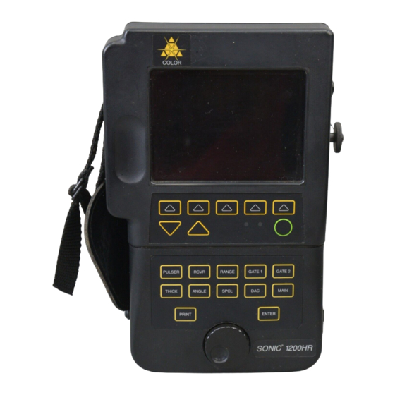
® Figure 4-1B: Sonic 1200HR Controls Power Button The POWER Button toggles instrument power on and off. Immediately after power is turned ON, an initialization routine is started. The instrument’s microprocessor determines the instrument configuration, performs power-up diagnostics and calibration, and readies the instrument for operation. - Page 46 approximately one half hour operating time remaining, a status message in the battery level window indicates a low-battery condition. A low-battery cutoff circuit will automatically switch the unit off to protect the batteries from excessive discharge. The instrument may be configured with either an electroluminescent (EL), monochrome, or color liquid crystal display (LCD).
-
Page 47: Soft Keys
Placing the LCD display in direct sunlight will result in temporary fade due to the elevation of internal liquid temperature beyond design specification. Shade or angle the display away from the sun to assure optimal function. i t i l i t ™... -
Page 48: Inc/Dec Arrow Keys
when repeatedly pressed, will toggle through specific parameter settings (discrete steps). The first time a soft key is pressed, the parameter located in the display box directly above the key will be highlighted using inverse video. INC/DEC Arrow Keys The Increase/Decrease arrow keys may also be used to change parameter settings. The parameter being adjusted will be displayed in inverse video directly above one of the menu soft keys. - Page 49 Sonic 1200S Operating Menu Keys GATE 1 GATE 2 THICK PULSER RCVR RANGE ANGLE MAIN SPCL GAIN GAIN GAIN GAIN GAIN GAIN GAIN GAIN GAIN GATE 2 DB DIFF RANGE GATE 1 T-GAUGE PULSE TRIG FREEZE POSN DISPLAY POSN TRIGGER DAMPING DELAY ANGLE...
-
Page 50: Enter Key
ENTER Key The ENTER key may be used to select a sub-menu, toggle a parameter value, execute or confirm an instrument operation, or respond to an instrument prompt. PRINT Key The PRINT key may be used to produce a hard copy output of the screen information to an external printer via the RS-232 I/O port. -
Page 51: Pulser Menu
4.11 Pulser Menu PULSER The PULSER menu key invokes the pulser menu shown and is used to adjust the operating characteristics of the square wave pulser. GAIN See GAIN parameter description in the Receiver menu section. PULSE Adjusts the square wave pulse width. The adjustment range is 30ns to 1200ns in 1ns increments. -
Page 52: Range Menu
wideband, 10 MHz tuned settings, and all RF displays to limit screen noise. The gain setting is a relative value and does not reflect actual overall signal gain. The instrument’s +dB feature is toggled OFF and ON alternately by pressing the gain soft key when the gain parameter is highlighted. -
Page 53: Gate 1 Menu
DELAY Adjusts the time base delay from -1.16 to 185 inches in steel. Adjustment step size varies from 0.001 to 1 unit. Refer to the VEL description for further Delay limits. VEL Selects the material sound propagation velocity. The adjustment range is 0.0250 in/µs to 0.6000 in/µs. -
Page 54: Gate 2 Menu
To access the Gate 1 second menu, press the GATE 1 key twice. This second menu sets up gate 1 parameters, such as scale and offset, for analog output of echo peak amplitude. When Gate 1 is turned off, the output 1 is set to 0mV. Thickness gauge operation disables Gate 1 outputs. SCALE Any value from 1000 mV to 4000 mV in 250 mV increments. -
Page 55: Thickness Menu
4.16 Thickness Menu THICK The THICK key calls up the thickness menu shown and is used to adjust the thickness gauge parameters. The thickness gauge controls are used to enable, configure, and calibrate the thickness gauge. The thickness gauge uses gate 1 for IP - 1 and both gates (1 and 2) for ECHO - ECHO. -
Page 56: Angle Menu
The allowable minimum and maximum values for part thickness and outer diameter are based on the T-velocity setting. If the instrument limits the adjustment for part thickness and outer diameter, it may be due to the current T-velocity setting. To access the Thickness second menu, press the THICK key twice. This second menu provides additional thickness gauge parameters. -
Page 57: Dac Menu
ANGLE This control enables/disables angle beam calculations and specifies the refraction of the sound beam into the test part (wedge angle). This control may be adjusted from 0° (OFF) to 90° in 0.1° increments. When an angle is specified, the sound path, depth, and distance measurements are displayed simultaneously. -
Page 58: Main Menu
SELECT/ADJUST This control allows selection of a new DAC point and/or amplitude adjustment of the selected DAC point. Amplitude adjustment is only available when the DAC control is set to DACONLY or DAC+CURV. CLEAR Allows clearing the DAC/DAC Curve. 4.19 MAIN Menu MAIN The MAIN key invokes the main menu and its parameters. -
Page 59: Spcl Menu
4.20 SPCL Menu SPCL ENTER * second menu item by pressing ENTER key. SPCL key provides parameters and features not associated with normal inspection operations. These include menus for front-panel lockout, date, program, A-Scan storage, and communications. Select SPCL menu parameters by pressing the appropriate column arrow soft key until the desired parameter box is highlighted. - Page 60 +dB VALUE Establishes the amount of gain applied by the +dB feature. The selections include +6 dB, +12 dB, +18 dB, and +24 dB. dB STEP Establishes step size used by SmartKnob and arrow keys to adjust gain value. Selections are 0.2, 1.0, 2.0, 6.0, and 12.0 dB. UNITS Selects various operating units.
- Page 61 A-LOC Selects the next storage location for an A-Scan. KNOB RES Knob Resolution allows selecting between 3-digit display or 4-digit display. REF MEM The Reference Memory function allows the operator to save a waveform through normal A-Scan save in the Main menu, recall it as “REF MEM”, then compare the “REF MEM”...
-
Page 62: Program Sub-Menu
4.21 Program Sub-Menu ® The Sonic 1200S/HR is capable of storing and retrieving 100 complete instrument programs. These setups are recorded with date and time, and may be named using up to 29 alphanumeric characters. Functions pertaining to program storage are store, recall, erase, name, and print. PROGRAM This line displays the program storage location which is to be stored, recalled, erased, named, or printed. -
Page 63: Report Form Sub-Menu
written test procedure, and so on. Only programs that are not empty may be named. PRINT The program print function uses the optional external serial printer option to make a hard copy of the currently selected program settings. 4.22 Report Form Sub-Menu ®... -
Page 64: Clock Sub-Menu
4.23 Clock Sub-Menu The Clock sub-menu is used to observe and modify the system clock parameters. The system date is expressed in DD MM YYYY format, while the system time is expressed in HH:MM format. MONTH Sets the system clock month (i.e., 1 = January, 2 = February, etc.). DAY Sets the system clock to the day of the month (days 1 through 31). -
Page 65: A-Scan Sub-Menu
4.24 A-Scan Sub-Menu ® The Sonic 1200S/HR is capable of storing and retrieving 100 complete A-Scans. These A- Scans are recorded with date and time, and may be named using up to 29 alphanumeric characters. A-Scans are stored in the MAIN menu using the A-LOC feature. Functions pertaining to stored A-Scans are recall, erase, name, and print. -
Page 66: A-Scan Attribute Sub-Menu
PRINT The A-Scan print function uses the optional external serial printer option to make a hard copy of the stored A-Scan, program settings, and a custom report form. ATTRIB Attribute appears only when A scan location is ALL. Press ENTER to access the A scan Attribute sub menu. -
Page 67: Data Sub-Menu
CLEAR The CLEAR function is for clearing the attribute of the highlighted A-Scan location. The attribute must be cleared before attempting to erase the location in the A-Scan Sub-Menu. A-SCAN Pressing this softkey or ENTER while it is highlighted returns unit to A-SCAN sub- menu. -
Page 68: New Block Editor
DESCRIBE The describe function allows the operator to enter an alphanumeric block description of up to 26 characters. DELETE Allows the operator to delete the selected block number. If it is desired to delete all data blocks, the block location must be set to the ALL state. Operator confirmation ENTER is required to complete the delete operation. -
Page 69: Block Review Sub-Menu
COLUMNS Sets the number of grid columns in this data block. The number of columns is adjustable in the range of 1 to 5000, but may be limited by the number of rows or available reading locations. DIR Sets the load direction for data storage. The selection (ROW or COLUMN) determines which index will advance after each store operation. -
Page 70: Text Editor
the location number. Setting the LOCATION number to less than 1 will allow the ALL selection for use by the CLEAR feature. ROW Changes the row selection, which in turn changes the location value. COLUMN Changes the column selection, which in turn changes the location value. T-MIN Establishes the minimum allowable thickness reading permitted by this block. -
Page 71: Instrument Reset
Right and Left Arrow Keys This line moves edit cursor left and right 1 character position (respectively). When the cursor exceeds either end of the string, its position wraps around to the other end. CLEAR Clears the entire text line and places the edit cursor at the first character. QUIT Terminates the text editor and aborts any changes made to the text string. - Page 72 64 Chapter 4...
-
Page 73: Applications
5. Applications What's in this section? • 5.1 Pulse-Echo Contact Thickness Testing • 5.2 Dual Transducer Thickness Testing • 5.3 Delay Line Thickness Testing • 5.4 Shear Wave (Angle Beam) Testing • 5.5 Distance Amplitude Correction (DAC) Testing Pulse-Echo Contact Thickness Testing One of the major methods of ultrasonic thickness testing is the pulse-echo contact method. - Page 74 COUPLANT — Use a couplant that “fills in” the surface. On smooth surfaces, thinner couplants can be used such as water, light oil, or mineral oil. On rough ® surfaces, Sonic X30S couplant (#3317450) is more appropriate. 5.1.1 Instrument Calibration - 0.5” Thickness Range, Steel Connect the transducer cable to the Spectrum™...
- Page 75 Press the RCVR menu key, then the DISPLAY menu soft key, and rotate the SmartKnob™ to select HALF-. Observe the signals and select “+” or “-” depending upon best signal display. Adjust Delay by pressing the RANGE menu key, then the DELAY menu soft key, and rotate the SmartKnob™...
- Page 76 5.1.2 Instrument Calibration - 1 to 10” of Aluminum Use the same procedure as the previous 0.5 inch steel test, but adjust the controls using 1-to-10 inch aluminum step blocks as the thin and thick steps. After calibrating at 1.0 inch and 10.0 inches, check at 5.0 inches for accuracy.
- Page 77 variations, and couplant thickness. In the Multiple Echo mode, the ultrasonic echoes being measured only include material thickness. Compensation for these offsets in the Multiple Echo mode is not required. 5.1.3 Alternate Calibration Test Method - Multiple Echo, 1.0 to 10.0”...
- Page 78 Place the transducer (with couplant) on the 1.0 inch thickness portion of the test block and press the RANGE menu key. Press DELAY menu soft key and rotate SmartKnob™ to line up the 1st echo on #1 graticule line. Press VEL menu soft key and rotate SmartKnob™ to line up the 5th echo with #5 graticule line.
- Page 79 Place couplant on the step block and position the transducer on the thinnest (0.100) step. Press RCVR menu key, then DISPLAY menu soft key, and rotate the SmartKnob™ to select HALF-. Observe the signals and select “+” or “-” depending upon best signal display.
- Page 80 ® Check the 0.200, 0.300 and 0.400 inch steps. If they line up, the Sonic 1200S/HR is calibrated. If not, repeat calibration steps 1 - 5. Figure 5-4: Echo From 0.100 Step and Figure 5-5: Echo From 0.500 Step 5.1.5 Digital Thickness Measurement From the Initial Pulse to the 1st Back Wall Reflection Press the GATE1 menu key and the following menu will appear.
- Page 81 Press the Gate POSN menu soft key and rotate the SmartKnob™, or press the POSN menu soft key repeatedly, to adjust the Gate position so that the start of the gate is to the left of the thinnest (0.100 inch) step (see Figure 5-6). Press the Gate WIDTH menu soft key and rotate the SmartKnob™, or press the WIDTH menu soft key repeatedly, to adjust the Gate width to full screen or to the right of the thickest step (0.500 inch).
-
Page 82: Dual Transducer Thickness Testing
Place the transducer on the thinnest step (0.100), press the THK CAL softkey and rotate ™ the SmartKnob until the THK CAL value for CAL PT2 reads 0.100 inch. Press the ENTER key to log this value. Calibration is now done. Check the 0.200, 0.300, and 0.400 inch steps. If the thickness readings are correct, the thickness gauge is calibrated. - Page 83 menu box, then rotate the SmartKnob™ or press the INC/DEC arrow keys to change the value. Place X30S couplant on the step block and position the transducer on the thinnest (0.100) step. Press the RCVR menu key, then the DISPLAY menu soft key, and rotate the SmartKnob™ to select HALF-.
- Page 84 ® 12. The Sonic 1200S/HR is now calibrated for steel from 0.100 inch to 0.500 inch This method provides an accurate test over this range. Figure 5-8. Pitch-Catch Echo from a 0.100 Step Block Figure 5-9. Pitch-Catch Echo from a 0.500 Step Block 5.2.2 Instrument Calibration - 1.0 to 10.0 Inches of Steel Use the same procedure as the previous 0.100 to 0.500 inch steel test, but adjust the controls...
- Page 85 ® The Sonic 1200S/HR is now calibrated for 10 inches of steel at full screen range with each major graticule division equal to 1 inch. Different materials will have different velocity, attenuation, and noise characteristics. The best accuracy will be obtained by using step blocks made from the same material as that being tested.
- Page 86 can be performed. In highly attenuative materials (for example, cast materials), it may not be possible to obtain multiple echoes over the desired thickness range, thus limiting this technique. The same accessories (transducer, cable, couplant) are used, except a block of only one known thickness is required, such as a B1 block with 1 inch thickness.
- Page 87 Repeat steps 4 and 5 until both echoes line up. All 10 echoes should then line up with a graticule line. If they do, the instrument is calibrated for 1.0 to 10.0 inches. If not, repeat calibration. After calibration, you are ready to start testing for flaws. If the calibration block surfaces are similar to the test material, you can proceed.
- Page 88 5.2.5 Thickness Measurement from Initial Pulse to 1st Back Wall Reflection Press the GATE1 menu key and the following menu will appear. This menu provides changeable parameters, such as Polarity, Position, Width, and Level, for either flaw or thickness measurements of Gate1. For thickness measurements, adjust the controls as follows: To enable Gate1, press GATE1 menu key again and rotate the SmartKnob™...
- Page 89 Press the Gate WIDTH menu soft key, and rotate the SmartKnob™, or press the WIDTH menu soft key repeatedly, to adjust the Gate width to full screen or to the right of the thickest step (0.500 inch). (Please refer to Figure 5-11). Press the THICK menu key and the following menu will display.
- Page 90 5.2.6 Thickness Using Multiple Echoes From the 1st Back Wall to 2nd Back Wall Reflection, Echo-to-Echo Adjust the operating controls as follows: To measure between echoes, both Gate 1 and Gate 2 are used for thickness measurements. Gate 1 position (start) must be to the left of the thinnest step (echo) for thickness measurements.
- Page 91 wide enough to cover the area where the 2nd back wall echo will appear (see Figure 5-13). Figures 5-12 and 5-13 Press GATE1 menu key and the following menu will appear. This menu provides changeable parameters, such as Polarity, Position, Width, and Level, for either flaw or thickness measurements of Gate1.
- Page 92 The Gate width must extend past the thickest step in the calibration procedure. Figures 14 and 15 Press the GATE2 menu key and the following menu will appear. This menu provides changeable parameters, such as Polarity, Position, Width, and Level, for either flaw or thickness measurements of Gate2.
- Page 93 Press the Gate WIDTH menu soft key and rotate the SmartKnob™, or press the WIDTH menu soft key repeatedly, to adjust the Gate width to go past or through the 2nd back wall echo (see Figure 5-17). Figure 16 and 17 For echo-to-echo measurements on thinner material than 0.500 inch, the Gate 2 position (start) and width must be adjusted for the thinnest echo-to-echo measurement, such as 0.200 inch (see Figure 5-18).
- Page 94 Gate 1 must start prior to the 1st echo (left side of echo) and the width must be wide enough so the 1st back wall echo passes through it. Place the transducer on the thinnest step (0.200 inch). Verify proper Gate1 and Gate2 positioning, as above (the thickness gauge starts the measurement with the 1st echo to break Gate1, and stops the measurement with the 1st echo to break Gate2).
-
Page 95: Delay Line Thickness Testing
Figures 19 and 20 5.2.7 Manual Echo-to-Echo Mode Calibration To calibrate the gage using Manual Echo-to-Echo mode, follow instructions for AUTO Echo- to-Echo calibration (see above) and instead of calibrating thickness using PT1 and PT2, do as follows: From the THICK Menu, set VELOCITY according to nominal material velocity. Place the transducer on the thin block and adjust OFFSET for the block value. - Page 96 echoes. Usually the range is from 0.010 inch to 0.500 inch, but it can go up to 0.750 inch. The measurement is made between the echoes (for best accuracy, the 1st and 2nd back echoes). The thickness gauge offsets, and sound velocity must be recalibrated, each time the instrument is powered up.
- Page 97 To select and change the following parameters, press the menu soft key below the selected menu box, then rotate the SmartKnob™ or press the INC/DEC arrow keys to change the value. Place couplant on the test block and position the transducer on the thinnest (0.100) step. Press the RCVR menu key, then the DISPLAY menu soft key, and rotate the SmartKnob™...
- Page 98 Figure 22: First Back Echo at 0.100” Move the transducer to the thickest (0.500) step. Adjust the Velocity by pressing the RANGE menu key, the VEL menu soft key, and rotating the SmartKnob™ to line up the leading edge of the first echo on the last graticule line (refer to Figure 5-23). Figure 23: First Back Echo at 0.500”...
- Page 99 Repeat steps 4 - 8 to verify that both the0.100 and 0.500 inch signals line up. ® Check the 0.200, 0.300 and 0.400 inch steps. If they line up, the Sonic 1200S/HR is calibrated. If they do not line up closely, repeat calibration steps 4 - 8. 5.3.2 Instrument Calibration - Other Ranges The instrument is calibrated similarly for other ranges and materials.
- Page 100 Press the Gate POSN menu soft key and rotate the SmartKnob™, or press the POSN menu soft key repeatedly, so that the start of the gate is to the left of the thinnest (0.100 inch) step (see Figure 5-24). Press the Gate WIDTH menu soft key and rotate the SmartKnob™, or press the WIDTH menu soft key repeatedly, to adjust the Gate width to full screen or to the right of the thickest step (0.500 inch).
- Page 101 Place the transducer on the thinnest step (0.100), press the THK CAL softkey and rotate ™ the SmartKnob until the THK CAL value for CAL PT2 reads 0.100 inch. Press the ENTER key to log this value. Calibration is now done. Check the 0.200, 0.300, and 0.400 inch steps. If the thickness readings are correct, the thickness gauge is calibrated.
- Page 102 Figures 26 and 27 Press GATE1 menu key and the following menu will appear. This menu provides changeable parameters, such as Polarity, Position, Width, and Level, for either flaw or thickness measurements of Gate1. For thickness measurements, adjust the controls as follows. To enable Gate1, press GATE1 menu key again, and rotate the SmartKnob™...
- Page 103 Figures 5-28 and 5-29 Press the Gate WIDTH menu soft key and rotate the SmartKnob™, or press the WIDTH menu soft key repeatedly, to adjust the Gate width until it goes past or through the 1st echo from the thinnest step (see Figure 5-29). The Gate width must extend past the thickest step in the calibration process.
- Page 104 Press the Gate POSN menu soft key and rotate the SmartKnob™, or press the POSN menu soft key repeatedly, so that the start of the gate is to the left of the 2nd back wall echo, or just to the right side of the 1st back reflection (see Figure 5-30). Press the Gate WIDTH menu soft key and rotate the SmartKnob™, or press the WIDTH menu soft key repeatedly, to adjust the Gate width to go past or through the 2nd back wall echo (see Figure 5-31).
- Page 105 12. Place the transducer on the 0.400 inch step. Verify proper Gate1 and Gate2 positioning, as above (a slight adjustment of the Gate2 position may be required to prevent triggering on unwanted signals), press the THK CAL softkey, and rotate the SmartKnob until the THK CAL value for CAL PT2 reads 0.400 inch.
-
Page 106: Shear Wave (Angle Beam) Testing
Figure 5-33 Shear Wave (Angle Beam) Testing The primary method of testing welds is Angle Beam Shear Wave Ultrasonic Inspection. The angle beam allows testing at the proper angle to detect flaws in the weld zone. This is accomplished by using a Lucite wedge to convert the ultrasound into a shear wave at the proper angle. - Page 107 5.4.1 Instrument Calibration - 10” Thickness Range, Steel ™ Connect the transducer cable to the Spectrum F2L transducer and to either BNC connector. Turn on instrument power and adjust the operating controls as follows: To select and change the following parameters, press the menu soft key below the selected menu box, then rotate the SmartKnob™...
- Page 108 Figure 5-34: IIW Block Type 1 60° 70° 75° 80° Figure 5-35: IIW Block Type 2 Swivel the transducer to peak the echoes. Calibrate the EL/LCD display to the sound path by adjusting Delay. Adjust Delay by pressing the RANGE menu key, then the DELAY menu soft key, and rotate the SmartKnob™, or press the UP/DOWN arrow keys, so that the first echo lines up as follows for the three test blocks: IIW Type 1 Block: Line 4 (4 inches).
- Page 109 30° 45° 60° 0° Figure 5-36: B1 Block Adjust Velocity by pressing the RANGE menu key, then the VEL menu soft key, and rotate the SmartKnob™ to line up the second echo as follows: IIW Type 1: Line 9 (9 inch). See second echo in Figure 5-37. IIW Type 2: Line 4 (4 inch).
- Page 110 Figure 5-37: IIW Type 1 Block Echoes Figure 5-38: IIW Type 2 Block Echoes 102 Chapter 5...
- Page 111 Figure 5-39: B1 Block Echoes All figures represent a 10 inch screen range. When the echoes are lined up at both points, the horizontal sweep is calibrated. Measurement of the wedge angle by use of a IIW Test Block: 10. If the index point of the wedge is not known exactly, it is first necessary to determine it. To find the true index point on the wedge: 11.
- Page 112 75° 60° 70° 80° Figure 5-40: Leading Edge Index Point a) Determination of the Angle of Refraction - The echo from the surface of the 2 inch (50 millimeter) diameter hole is used. The calibration markings engraved on both sides of the block make a direct determination of angles between 35×...
- Page 113 (2.) Read the angle from the true index mark to where it reads on the degree marks on the block. (Use the other side for above 60°). 70° 60° 75° 80° Figure 5-41: IIW Block Refraction Angle Calibration b) B1 Block Refraction Angle Transducer Locations - For the B1 Block, use the reflection from the side drill hole, as shown in Figure 5-42, and maximize the echoes as before.
- Page 114 14. The measured angle should be within the specifications of the code or procedures used, normally ±2 degrees. Figure 5-42: B1 Block Refraction Angle Transducer Locations 15. Setting the reference level: Set the echo signal level according to the specific code requirement.
- Page 115 5.4.2 Defect Location in Weld Inspection It is important to determine the distance and depth of a located flaw or defect in a shear wave ® test. A Sonic Ultrasonic Calculator for Weld Inspection can be used to graphically locate defects, or simple sine-cosine trigonometry can be used.
- Page 116 5.4.3 Multiple Bounce Weld Inspection If the sound path bounces or reflects one or more times from the sides of the test piece, the sound path and surface distance readings will be the same as for direct reflection. However, the depth calculation will give a result greater than the actual thickness (as shown in Figure 5-45).
- Page 117 Example: W = 1 inch and S = 3 inches and angle 0 = 60° then: depth(2) = 3 • cos 60° = 1.5” actual depth(1) = (2 x 1”) - 1.5” = 0.5” Shear Wave (Angle Beam) Digital Thickness Calibration Once the screen range is calibrated, continue with the setup of the Angle Beam (Trig functions) mode.
- Page 118 Figures 5-46 and 5-47 Ensure that both echoes (thinnest and thickest) go through the gate bar. The Thickness Gauge is now ready for calibration. a) Press the THICK menu key and the following soft key menu will appear: ™ b) Press the T-GAUGE menu soft key and rotate the SmartKnob , or press the UP/DOWN arrow keys, to turn on T-gauge to A IP-1st.
- Page 119 Calibration is now done. (see Figure 5-50.) Figure 5-48 Figure 5-49 Applications 111...
-
Page 120: Distance Amplitude Correction (Dac) Testing
Figure 5-50 g) Press the TRIG menu soft key and turn ON the trig function by using the UP/DOWN arrow keys or SmartKnob™. h) Press the ANGLE menu soft key and adjust the incidence angle to the desired value using the UP/DOWN arrow keys, SmartKnob™, or by pressing the ANGLE menu key repeatedly. - Page 121 CURVES; 3) 4 CURVES; 4) DACONLY; and 5) DAC+CURV. For setup purposes, start with the DAC CURVONLY. Be sure the Sonic 1200S/HR instrument is set up with the correct transducer setting. Adjust the screen range parameter to include the total range of the test part. For setup purposes, the screen display is for multiple echoes (see Figure 5-51).
- Page 122 Press the SELECT menu soft key; this will start the DAC Curve and log the point. Press the CURSOR menu soft key, and with the UP/DOWN arrow keys or SmartKnob™, adjust the cursor to the second point/echo (see Figure 5-53). Press the SELECT menu soft key;...
- Page 123 5.5.2 DACONLY Press the CURSOR menu soft key and a small circle will appear on the display that selects the points/echo where DAC compensation is calculated and the amplitude of the selected points is adjusted. With the UP/DOWN arrow keys or the SmartKnob™, move the cursor to the point/echo where the DAC Only is to start (see Figure 5-56).
- Page 124 Figure 5-56 - 59 Press the CURSOR menu soft key, and with the UP/DOWN arrow keys or SmartKnob™, adjust the cursor to the next point/echo (see Figure 5-60). 116 Chapter 5...
- Page 125 Press the SELECT menu soft key, this will log the next point/echo. SELECT will automatically change to ADJUST. With the UP/DOWN arrow keys or SmartKnob™, adjust the gain to increase the echo amplitude to the desired height: for example, from 60% FSH to 80% FSH.
- Page 126 5.5.3 DAC+CURV Press the DAC menu soft key, and with the UP/DOWN arrow keys or the SmartKnob™, select the DAC+CURVE mode. Press the SELECT menu soft key; this will log all the Dac Curve points and automatically draw for the selected points/echoes (see Figure 5-63). If the points/echoes are adjusted to the correct amplitude, the DAC+CURVE is complete.
-
Page 127: Internal Datalogger
6. Internal Data Logger What’s in this section? • 6.1 Introduction • 6.2 Creating a New Block • 6.3 Selecting a New Block • 6.4 Storing Readings into Memory • 6.5 Selecting Locations and Reviewing Readings • 6.6 Clearing Readings •... -
Page 128: Creating A New Block
Data Logger memory can be cleared. The Sonic 1200S/HR stores readings in memory indefinitely, even when the batteries have been removed. However, data could be lost or corrupted if the instrument were damaged or exposed to extreme environmental conditions. -
Page 129: Selecting A Block
Enter an 8 character block name by pressing the NAME menu soft key (also available in the Data sub-menu). Enter a 26 character block description by pressing the DESCRIBE menu soft key (also available in the Data sub-menu). Ensure that the correct number of rows, number of columns, and storage direction are selected before leaving this menu. -
Page 130: Selecting Locations And Reviewing Readings
The enlarged thickness reading is automatically displayed in the numeric display portion of the screen. To record a displayed thickness value in the current location, press the T-STORE menu soft key. Once the reading has been stored, the block location number will be incremented automatically. -
Page 131: Clearing A Block
Clearing a stored reading permanently erases it from memory. It cannot be recovered. The contents of the currently selected block location will be permanently lost. However, the contents of the data block may be transferred to a printer or personal computer prior to clearing. -
Page 132: Deleting A Block
Use the SmartKnob™ to decrease the location number until the word ALL appears. Clearing a stored reading permanently erases it from memory. It cannot be recovered. Press the CLEAR menu soft key Press the ENTER key to confirm the clear operation, any other key to abort. All locations in the data block have been cleared and are available for recording of measurement data. - Page 133 To delete the entire Data Logger memory: Display the Data sub-menu SPCL, DATA sub-menu, ENTER. Press BLOCK menu soft key. Decrease the block number below 1 until the word ALL appears. Clearing a stored reading permanently erases it from memory. It cannot be recovered.
- Page 134 126 Chapter 6...
-
Page 135: Computer Interface
7. Computer Interface What’s in this section? • 6.1 Description • 6.2 RS-232C Communication • 6.3 Modes of Operation • 6.4 Command Strings • 6.5 Status Reporting • 6.6 RS-232 Command Set • 6.7 Examples Description ® The Sonic 1200S/HR instrument has the capability of being controlled and monitored by an external computer or terminal. -
Page 136: Communication
Using a readily available 9-pin to 25-pin serial adapter cable, it will also connect to standard IBM-PC serial connectors by using a 25-pin to 25-pin cable with female connectors on both ends. Interface cables are also available from Olympus NDT Instruments. 128 Chapter 7... - Page 137 Proper connections of the serial port to various devices are tabulated below: 7.2.1 9-Pin Auxiliary Output The 9-pin, D-subminiature female connector, labeled OUTPUT, provides optional alarm and analog level signals from the gates and the thickness gauge. Separate digital and analog ground pins and a pulse for synchronizing to the pulser are also provided.
-
Page 138: Modes Of Operation
Modes of Operation Two communication modes are available: HOST mode, which permits computer communication with the instrument, and TERMINAL mode, which is designed for use with a ® terminal. Each time the Sonic 1200S/HR is powered on, the operating mode is set to HOST ®... -
Page 139: Status Reporting
return (terminator). The command string has three parts, not all of which are used in every case. Command Code: A three character code that identifies the instrument item or function (refer to RS-232 Command Set). Command Operation: A one character code that identifies the operations as READ ‘?’, WRITE ‘=’, or EXECUTE (carriage return). -
Page 140: Command Set
RS-232 Command Set ® RS-232 control of the Sonic 1200S/HR is achieved using ASCII command strings terminated by a carriage return (0D Hex). For commands that require ASCII letters A-Z (or a-z), upper or lower case may be used. Space (20 Hex) and line feed (0A Hex) characters may be included in the command strings (that is, spaces may be included in report strings), but are usually ignored. - Page 141 1 " " z 2 " " z 5 " " z 1 " " z 1 " " z ) y l H " " S " " B " , " + " , " " - " r a l y t i r a l...
- Page 142 " " F " " T " " " " T " " " " " " ) y l µ ( s f f s f f µ / y t i y t i " " F " "...
- Page 143 o i t o i t s t l o i t l l a o i t o i t e t i e t i o i t E " " Y F " " L P " , "...
- Page 144 ) s t t i b i t c ) s t e t i l t r e t i e i f e t i e i f y r t y r t e t i r t n y r t g i l i l k...
- Page 145 i t c i r c i t p O " " F s u t a t s s u t O " " N f i D r e f r e f f i d r e f O "...
- Page 146 " " F l o r " " N " " F l o r " " N E " " H F " " S D " " H i t a E " " L " " O R "...
- Page 147 i h t t n i t n i r e t r e t t f o t f o t f o t f o t f o o i t o i t u r t u r t r o t r o t Computer Interface 139...
- Page 148 t r o , r e , s l e i f t r o i r t u r t u r t l l A s t l t l u s t l t r o , r e t l u a r t , t s...
- Page 149 Computer Interface 141...
- Page 150 Text Read/Upload Commands The instrument responds to text read commands with an ASCII string terminated with a carriage return (0D Hex). To ensure proper transfer, the following steps are used to upload a text string: a) Host sends a “Read Text” command. ®...
-
Page 151: Examples
This command is used to send stored binary data, acquired through the corresponding binary ® ® upload command, back to the Sonic 1200S/HR. The Sonic 1200S/HR assumes that the data has not been altered. Altered data will yield unpredictable results. To ensure proper transfer, the following steps are used to download stored data. - Page 152 Example 3.Set report label 1 string to L ...L S L B = ® u r t Example 4.Read report label 1 text string. R L B = ® u r t Example 5.Upload stored program 1. P U P = ®...
- Page 153 Documentation Comments Olympus NDT is always interested in improving its documentation. Please complete this questionnaire and return your responses to: Olympus NDT info@OlympusNDT.com Attention: NDT Marketing Dept., Technical Publications The following questionnaire is from the Society for Technical Communication and “Revision Checklist”...
- Page 154 Is everything accurate? Are the main points properly stressed? Are there sufficient examples? Writing and Editing Is the reading level appropriate to the audience? Are the tone and style appropriate for the purpose and audience? Is terminology consistent? Are grammar, syntax, spelling, and punctuation correct? Illustrations Do the illustrations contribute to the usefulness of the document? Are the illustrations effectively integrated into the text?
Need help?
Do you have a question about the Sonic 1200S/HR and is the answer not in the manual?
Questions and answers