
Subscribe to Our Youtube Channel
Related Manuals for Olympus Panametrics Epoch 4 Plus


Summary of Contents for Olympus Panametrics Epoch 4 Plus
- Page 1 ® Advanced Test Equipment Rentals www.atecorp.com 800-404-ATEC (2832) USER’S MANUAL EPOCH 4PLUS Part No. 910-250C...
- Page 2 Refer to your local Olympus distributor for return and/or collection systems available in your country. Copyright 2005 by Olympus NDT, Inc. All rights reserved.
- Page 3 For these reasons, we make no warranty, expressed or implied, that the techniques, examples, or procedures described herein are consistent with industry standards nor that they will meet the requirements of any particular application. Olympus expressly disclaims all implied warranties of merchantability and of fitness for any particular application.
- Page 4 EPOCH 4PLUS...
-
Page 5: Table Of Contents
Table of Contents Table of Contents Warranty Table of Contents Preface ............1 Product Description . - Page 6 EPOCH 4Plus 3.7.7 VGA Output On/Off ........28 3.7.8 Beep On .
- Page 7 Table of Contents Calibrating the EPOCH 4PLUS ........55 Getting Started .
- Page 8 EPOCH 4Plus 9.4.9 Advanced DAC/TVG and the EPOCH 4PLUS Datalogger..102 Low Pulse Repetition Frequency (LPRF) ......102 9.5.1 Activating LPRF Mode .
- Page 9 Table of Contents 9.14.4 BEA and the EPOCH 4PLUS Datalogger ..... . 142 9.15 Auto-Freeze ........... . 143 9.16 AWS .
- Page 10 EPOCH 4Plus...
-
Page 11: Preface
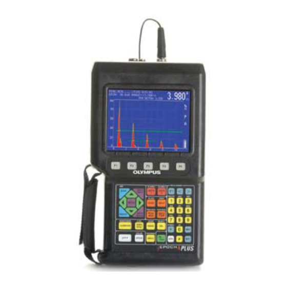
Preface Preface The preface provides the following introductory topics: • Product Description • About this Document • Audience • Typographic Conventions • Related Documentation • If You have Documentation Comments • Revision History • Technical Help Product Description The EPOCH 4PLUS is a lightweight, portable flaw detector offering ultrasonic performance, resolution, and documentation capabilities with a color display that has special advantages over basic, traditional displays. -
Page 12: About This Document
We assume no responsibility for incorrect operational procedure or interpretation of test results. We recommend that any operator seek adequate training prior to using this equipment. Olympus NDT offers a full range of training courses including Level I and Level II Ultrasonic Testing, Advanced Detection and Sizing, and Ultrasonic Thickness Gaging. -
Page 13: Typographic Conventions
Olympus documentation. Complete the survey at the back of this manual and send your documentation comments to Olympus NDT by using one of the following methods: • Send comments to Olympus NDT. Attention: Technical Publications •... -
Page 14: If You Have Documentation Comments
The table below shows a list of all revisions for this document. Date Issue Release version September 2003 910-250A First release July 2005 910-250B Revision December 2005 910-250C Revision Table 2 Revision History Technical Help Call Olympus NDT and ask for a sales engineer to assist you. -
Page 15: Operating The Power Supply
Operating the Power Supply Operating the Power Supply This chapter describes how to operate the EPOCH 4PLUS using different power supply options. Topics are as follows: • Using AC Line Power • Using Battery Power • Operating Time for the Battery •... -
Page 16: Operating Time For The Battery
EPOCH 4PLUS Operating Time for the Battery The EPOCH 4PLUS operating time on battery power varies depending on the display type and use conditions. Using a 360 Hz measurement rate allows a minimum of four (4) hours operation, and a measurement rate of 30 Hz provides up to six (6) hours operation. The pulser must be set to square wave at 5 MHz, high power settings to achieve maximum battery operating time. -
Page 17: Using A "Aa" Alkaline Battery
This accessory is available through Olympus NDT (part number EP4/EC) or found locally in electronic and retail stores. Contact Olympus NDT for more information. If the battery is used daily (or frequently), connect it to the Charger/Adapter when not in use. - Page 18 EPOCH 4PLUS...
-
Page 19: Managing Basic Operations
Managing Basic Operations Managing Basic Operations This chapter describes how to get started with basic EPOCH 4PLUS operations. Topics are as follows: • Powering-up • Using the Keypad • Summarizing Keypad Functions • Managing the Display • Setting-up Parameters • Customizing Colors Powering-up/LCD Screen Adjustment Pressing [ON/OFF] causes an initial beep from the unit and then a series of relay clicks. -
Page 20: Using The Keypad
EPOCH 4PLUS visibility. You can slew through a wide range of the adjustment to optimize the display. Using the Keypad The most commonly used keys on the keypad (Gain, Freeze, Save, Enter, and Slewing Keys) are close to your left thumb. The keypad is grouped and color-coded according to function. - Page 21 Managing Basic Operations When an operator accesses a parameter from the main keypad, preset value s are displayed at the bottom of the screen. Each preset value has a corresponding function key. For example, press [RANGE] to view various preset range values at the bottom of the display. Press any one of the function keys to set the range to that displayed value.
-
Page 22: Main Keypad Functions
EPOCH 4PLUS Figure 2 International Keypad 3.3.1 Main Keypad Functions English Int’l Color Function Blue Sensitivity: Adjusts system sensitivity. COLOR COLOR White Option: Accesses the instrument’s setup menu and software options. Table 3 Main Keypad Functions... - Page 23 Managing Basic Operations English Int’l Color Function White 2nd Function: Press the [2nd F] key with a key that has dual functions (the main function written on the key; the secondary function written above the key), and the secondary function becomes active.
- Page 24 EPOCH 4PLUS English Int’l Color Function Gate 2: Controls the positioning of Gate 2 on the display. Press this key multiple times, or use the function keys, to access Gate 2 Start, Gate 2 Width, and Gate 2 Level. White Gate 2 Alarm: Activates the alarm mode for Gate 2.
-
Page 25: Datalogger Keypad Functions
Managing Basic Operations English Int’l Color Function White Echo-to-Echo Measurement: Activates the Echo-to-Echo Measurement mode. This automatically opens Gate 2 (if it is not Orange already active) and allows you to select edge to edge or peak to peak measurement using the function keys. Yellow Auto Calibration: Initiates the EPOCH 4PLUS Auto Calibration... - Page 26 EPOCH 4PLUS English Int’l Color Function Blue Move Cursor Right: Moves the cursor to the right one space each time this key is pressed when the datalogger is opened, and you are entering/editing a directory name, filename, etc. White Alpha Entry: Allows entry of the characters that are in beige-colored text above the numbers keys.
-
Page 27: Editable Parameters Software
Managing Basic Operations KEYS COLOR FUNCTION Yellow Alphanumeric Entry: Entry of alphanumeric characters. The numeric characters are entered after pressing the [#] key. The alpha characters are entered after pressing the [ALPHA] key. The Delete function is used to erase a number or character. - Page 28 EPOCH 4PLUS Figure 3 Selecting the Editable Parameters Option 3. Press [ENTER]. The Editable Parameters screen opens: Figure 4 Viewing the Editable Parameters Screen 4. Press the [ENTER] key to move downward to different parameters. 5. Use the left and right slewing keys to select which [F1] - [F5] parameter to edit. Edit each parameter using the up and down slewing keys.
- Page 29 Managing Basic Operations Figure 5 Editing the Gain Parameter 6. Press the [F1] key, when you have finished editing the parameters, to save the settings and return to the Options menu. When you select one of the parameters that you edited, the new preset values appear above the [F] keys.
-
Page 30: Color Settings
EPOCH 4PLUS • Live A-Scan • Peak Memory/Peak Hold A-Scan • Gates (all gates may be the same color depending on color availability) • Text (parameters, popup boxes, and option menu) and Grid • DAC, TVG, DGS, and other curves •... -
Page 31: Split Screen Display
Managing Basic Operations Figure 7 Full Screen Display Top of the screen • The Filename, Gain level, ID Code, Range setting, and currently selected parameters are constantly displayed. • A numeric display shows thickness, soundpath, amplitude, or Time-of-Flight data pertaining to a gated signal. Use [DEPTH /%AMPL] to select which information to show. -
Page 32: Display Flags And Markers
EPOCH 4PLUS 1. Press [DISPLAY] to toggle the display to the split screen. Figure 8 Split Screen Display 2. Press [ENTER] several times to toggle through the instrument parameters. 3. Use the [ ], [ ], [ ], and [ ] keys to change the setting from the current highlighted function. -
Page 33: Setting-Up Parameters
Managing Basic Operations Indicates the EPOCH 4PLUS is in the Echo-to-Echo measurement mode and the measurement is being made between the leading edges of the two selected signals. Indicates the Peak Memory function is active. Indicates the Peak Hold function is active. Indicates the display is frozen because the Freeze function is active. -
Page 34: Language Selection
EPOCH 4PLUS Figure 9 Menu Options The selections in the Setup menu are grouped according to function. Use the green slewing keys to move around this menu. Press [ENTER] to select/deselect an item. Press [OPTION] to return to the live screen Symbol Description Another menu is available. -
Page 35: Units Of Measurement
Managing Basic Operations displaying in terms of distance, the screen can be set to be viewed either in units per division (for example 1.000in/div or 25.00mm/div) or units full scale (for example, 10.00” full scale or 250 mm full scale). Units full scale describes the distance over the entire screen range. -
Page 36: Advanced User
EPOCH 4PLUS 3.7.5 Advanced User Several EPOCH 4PLUS functions can be customized with either a standard setting or an advanced setting for users needing additional flexibility and control. All functions are reset to the standard setting with an instrument Master Reset or when it initially ships from the factory. -
Page 37: Usb Connector
EPOCH 4PLUS and a PC. The most common use of this port is communication with a PC via the EPOCH 4PLUS GageView PRO Interface Program (contact Olympus NDT or you local representative for further details). Part # 910-250C... -
Page 38: Vga Output On/Off
EPOCH 4PLUS The external trigger allows the EPOCH 4PLUS to trigger in or trigger out communications with an external device via the parallel port. 3.7.7 VGA Output On/Off The VGA output on the EPOCH 4PLUS lets you view the full color screen display on a PC monitor, projector, or a heads-up display. -
Page 39: Filled Live
Peak Memory or Peak Hold feature appears filled-in, rather than as an outline trace. 3.7.13 “AA” Alkaline Battery Selection When using the Alkaline battery pack offered by Olympus NDT , the Alkaline Bat. selection in the System Setup menu should be highlighted. This allows for maximum battery operating time. - Page 40 EPOCH 4PLUS...
-
Page 41: Adjusting The Pulser Receiver
Adjusting the Pulser Receiver Adjusting the Pulser Receiver This chapter describes how to adjust the pulser receiver. Topics are as follows: • Adjusting System Sensitivity • Using AUTO-80% • Setting Gain Reference Level and Adding Scanning Gain • Using the Pulser Key Adjusting System Sensitivity To adjust the instrument sensitivity, follow these steps: 1. - Page 42 EPOCH 4PLUS Figure 10 Before Activating AUTO-80% To use Auto-80% with Gate 2, follow these steps: 1. Press [GATE 2]. 2. Press [F4] to turn on the gate if necessary. 3. Use the green slewing keys to position the gate over the desired echo. Be sure the echo breaks the gate threshold.
-
Page 43: Setting A Gain Reference Level And Adding Scanning Gain
Adjusting the Pulser Receiver Note: You can use AUTO-80% when an echo exceeds the desired amplitude. The echo can be either above or below 80% full screen height. If a signal is above 80% screen height, the EPOCH 4PLUS reduces gain in a series of repetitions until the signal peaks at 80%. -
Page 44: Using The Pulser Key
EPOCH 4PLUS Using the Pulser Key The following pulser receiver and filter parameters can be adjusted on the EPOCH 4PLUS keypad: • Waveform Rectification • Pulser Energy • Pulser Damping • Pulser Test Mode • Filter Selection • Pulser Type (square wave or spike excitation) •... -
Page 45: Pulser Energy
Adjusting the Pulser Receiver 2. Use the function keys for direct access or the [ ] and [ ] keys to toggle through the different waveform rectification modes. 4.4.2 Pulser Energy The EPOCH 4PLUS has four (4) pulser energy settings depending upon test conditions: •... -
Page 46: Test Mode
EPOCH 4PLUS 2. Use the function keys for direct access or the [ ] and [ ] keys to toggle through the four available damping selections. 4.4.4 Test Mode The EPOCH 4PLUS can operate in three test modes: Pulse-Echo Mode: Single element transducers. - Page 47 Adjusting the Pulser Receiver transducers or changing to a different application. However, the signal to noise ratio may not be as great as when a narrowband filter is selected. The following preset filter selections are available in Standard User mode: •...
-
Page 48: Pulser Type Selection
EPOCH 4PLUS Your selections for low and high filter frequencies are generally a function of the transducer frequency. We recommend that you select a High Pass Filter setting below the transducer frequency being used and select a Low Pass Filter setting above the transducer frequency being used. -
Page 49: Pulser Frequency Selection
Adjusting the Pulser Receiver 4.4.7 Pulser Frequency Selection Pulser Frequency Selection is applicable only when the square wave pulser is selected. The frequency selection is designed to tune the square wave pulser to obtain the best performance for the transducer being used. The Pulser Frequency Selection is viewable on the display only when the EPOCH 4PLUS is in the Square Wave Pulser mode. - Page 50 EPOCH 4PLUS...
-
Page 51: Managing Special Waveform Functions
Managing Special Waveform Functions Managing Special Waveform Functions This chapter describes how to manage special waveform functions. Topics are as follows: • Reject • Peak Memory • Peak Hold • Screen Freeze Reject The Reject function eliminates unwanted, low-level signals from the display. Because the EPOCH 4PLUS features a digital waveform display, the reject function is linear. -
Page 52: Peak Hold
EPOCH 4PLUS A “P” appears at the right side of the display to indicate the function is active. 2. Scan over the reflector to acquire the echo envelope. Continue to scan slowly until the live waveform peak matches the peak amplitude of the echo envelope. When these two points match, the signal will be peaked up. - Page 53 Managing Special Waveform Functions you can do a variety of functions such as storage of the waveform or thickness data and entry of an alphanumeric location code or memo to describe the data. It is possible to manipulate the gates to obtain thickness or soundpath data. The Freeze function differs from Peak Memory in that no new data is acquired and added to the instrument display.
- Page 54 EPOCH 4PLUS...
-
Page 55: Using The Gates
Using the Gates Using the Gates This chapter describes how to use the gates in the EPOCH 4PLUS. Topics are as follows: • Positioning Gate 1 • Positioning Gate 2 • Taking Thickness Readings • Taking Echo-to-Echo Thickness Readings • Locating Flaws with an Angle Beam Transducer •... -
Page 56: Taking Thickness Readings
EPOCH 4PLUS 3. Press [GATE 1] to switch back to control Gate 1. 4. To turn Gate 2 off, press [GATE 2] followed by [F4]. Taking Thickness Readings The EPOCH 4PLUS is equipped with a high resolution distance calculator that provides a direct readout of thickness, soundpath, or Time-of-Flight data across the top of the A- Scan. -
Page 57: Taking Echo-To-Echo Thickness Readings
Using the Gates While in Edge Depth mode, thickness readings are made to the leading edge of the first signal to exceed the flaw gate level. In Peak Depth mode, thickness readings are made to the peak of the highest amplitude signal that falls within the gate. If no refracted angle is entered, a Minimum Depth value appears above the display. -
Page 58: Locating Flaws With An Angle Beam Transducer
EPOCH 4PLUS For example, if Gate 1 Start is set to 0.25" (6.35 mm) and Gate 2 Start is set to 0.40" (10 mm), then the blank period is 0.15" (3.8 mm) of metal path. If the first detected echo breaks Gate 1 at 0.35"... -
Page 59: Measuring Signal Amplitude
Using the Gates These symbols represent the following distances: = angular (soundpath) distance to the reflector = surface distance (projection) to the reflector = depth to the reflector = soundpath leg that the particular reflector is located in – 1st, 2nd, 3rd, 4th, beyond 4th The selection of the Measurement modes (Peak Depth or Edge Depth) and the appropriate soundpath reading type are displayed in large text. -
Page 60: Operating Time-Of-Flight (Tof) Mode
EPOCH 4PLUS If an echo exceeds the gate threshold and the EPOCH 4PLUS is in the Amplitude mode, the amplitude information for that echo is displayed as a percentage of Full Screen Height as both Current Amp and Amp Max. Figure 14 Amplitude Mode Displaying Current Amp and Amp Max Current refers to the real time percentage of screen height of the highest amplitude signal... -
Page 61: Using The Zoom Feature
Using the Gates Figure 15 Time-of-Flight Mode Displaying µs Values To setup the Time-of-Flight mode, follow these steps: 1. Press [OPTION]. 2. Move the highlight bar over Setup and press [ENTER]. 3. Move the highlight bar over Unit and press [ENTER]. 4. -
Page 62: Activating Gate Alarms
EPOCH 4PLUS detailed view of an indication and to make better judgements regarding flaw location and depth. Zoom is useful when inspecting particularly large or thick components when detail is lost due to using long screen ranges. Use the Zoom function to look at small sections of the test piece without disturbing the instrument’s original calibration. -
Page 63: Minimum Depth Alarm
Using the Gates Figure 17 Positive Logic Alarm 4. Press [2nd F], [GATE 1] (ALARM 1) and then press [F4] for OFF to shut off the Gate 1 alarm. 5. Press [2nd F], [GATE 2] (ALARM 2) and then press [F4] for OFF to shut off the Gate 2 alarm. -
Page 64: Minimum Depth Alarm In The Echo-To-Echo Measurement Mode
EPOCH 4PLUS 6.9.4 Minimum Depth Alarm in the Echo-to-Echo Measurement Mode Use the minimum depth alarm when making Echo-to-Echo thickness readings. In Echo- to-Echo mode, the minimum depth marker appears on Gate 2. To set the minimum depth alarm when in Echo-to-Echo mode, follow these steps: 1. -
Page 65: Calibrating The Epoch 4Plus
Calibrating the EPOCH 4PLUS Calibrating the EPOCH 4PLUS This chapter describes how to calibrate the EPOCH 4PLUS. Calibration is the process of adjusting the unit so that it measures accurately on a particular material, using a particular transducer at a particular temperature. You must adjust the Zero Offset and Velocity parameters of the EPOCH 4PLUS during calibration. -
Page 66: Calibrating With A Straight Beam Transducer
Ideally the two thicknesses should represent thicknesses that are both below and above the expected thickness of the material being inspected. For this example, we are using Olympus NDT standard 5-step steel test block part number 2214E. The steps measure 0.100", 0.200", 0.300", 0.400", and 0.500". - Page 67 Calibrating the EPOCH 4PLUS 3. Couple the transducer to the THIN calibration block step. For this example, the transducer is coupled to the 0.200" step (depending on the frequency of the contact transducer being used, it may be impossible to obtain a proper reading on a very thin material).
- Page 68 EPOCH 4PLUS Figure 20 Calibrating for a Thick Block Using a Straight Beam Transducer 8. A thickness reading appears in large text above the A-Scan. Once a steady reading is achieved, press [VEL]. The screen freezes and a pop-up box appears again on the screen.
-
Page 69: Calibrating With A Delay Line Transducer
For this example, we are using Olympus NDT standard 5-step steel test block part number 2214E. The steps measure 0.100", 0.200", 0.300", 0.400", and 0.500". - Page 70 EPOCH 4PLUS Figure 22 Calibrating for a Thin Block Using a Delay Line Transducer 5. Press [ZERO OFFSET] once the reading is steady. The screen freezes and a pop-up box appears on the screen. Use the alphanumeric keypad to enter the exact known thickness of the test sample. For this example, press [1], [0], [0].
-
Page 71: Calibrating With A Dual Element Transducer
Calibrating with a Dual Element Transducer The sample delay line calibration described below is performed using Olympus NDT transducer part number DHC711-RM, with a frequency of 5.0 MHz and an element... - Page 72 For this example, we are using Olympus NDT standard 5-step steel test block part number 2214E. It has steps measuring 0.100", 0.200", 0.300", 0.400", and 0.500".
- Page 73 Calibrating the EPOCH 4PLUS 4. Position Gate 1 so that the leading edge of the backwall echo from the known thickness step is exceeding the gate threshold. A thickness reading appears in large text above the A-Scan. Figure 26 Calibrating for a Thin Block Using a Dual Element Transducer 5.
-
Page 74: Calibrating With An Angle Beam Transducer
Calibrating with an Angle Beam Transducer The sample angle beam calibration described below is performed using Olympus NDT transducer part number A430S-SB, with a frequency of 2.25 MHz and an element diameter of 0.625" x 0.625". The transducer is mounted on a 45 wedge, part number ABWS-6-45. -
Page 75: Locating The Beam Index Point (B.i.p.)
Calibrating the EPOCH 4PLUS Connect the transducer to an appropriate cable and then connect the cable to either of the transducer posts on the EPOCH 4PLUS. 2. Enter the correct refracted angle for the transducer/wedge combination. For this example, enter 45 3. -
Page 76: Verifying The Refracted Angle (Beta)
EPOCH 4PLUS draws and collects the echo envelope of the signal while also drawing the live waveform. Match the live waveform with the maximum point corresponding to the previously accumulated echo dynamic curve. Refer to the figure above for a detailed schematic of using the Peak Memory feature to find the BIP. -
Page 77: Calibrating For Distance
4" (100 mm) and 9" (225 mm) on the screen. The U.S. Air Force IIW Type II Block, which has a large cutout in the side, produces echoes at 2" and 4" on the screen. The procedure below uses the Olympus NDT IIW Type I carbon steel calibration block, part number TB7541-1. - Page 78 EPOCH 4PLUS 2. Press [CALIBRATION]. A Cal symbol appears to the right of the A-Scan, signifying the EPOCH 4PLUS is in Auto-Calibration mode. To exit the Auto-Calibration mode at any point, press [ENTER]. 3. Position Gate 1 so that the echo reflection from the 4" arc (this should be the first large echo after the Main Bang) is exceeding the gate threshold.
-
Page 79: Calibrating For Sensitivity
Calibrating the EPOCH 4PLUS spreading and sound bouncing off the side of the block. Make sure Gate 1 is not over this echo. Figure 35 Adjusting the Gain 8. Press [VEL] once the reading is steady. The screen freezes and a pop-up box appears again on the screen. - Page 80 EPOCH 4PLUS Figure 37 IIW Calibration Block with 0.060" Diameter Drilled Hole 2. Move the probe forward and backward until you have “peaked up” the return signal from the hole (that is, found the maximum amplitude). Do not confuse the reference reflector echo from the side of the block.
-
Page 81: Managing The Datalogger And Data Communication Features
Managing the Datalogger and Data Communication Features This chapter describes how to manage the EPOCH 4PLUS datalogger. Olympus NDT has designed the datalogger for ease of use while providing a wide range of features for virtually all flaw detection and thickness gaging requirements. It includes the following capabilities: •... -
Page 82: Using The Memory Screen
EPOCH 4PLUS Soundpath leg of measurement Thickness/Soundpath values (Edge or Peak Depth mode), Current and Maximum Amplitude data (Amplitude mode), or Time-of-Flight data (Microsecond mode). • Complete Waveform/Parameter Setup All data listed in the Thickness Reading section Waveform screen Peak Memory echo envelope or Peak Hold frozen waveform (if selected) Complete setup parameters Flag status (Freeze, Zoom, Peak Memory, etc.) •... -
Page 83: Using The Alphanumeric Keypad
Managing the Datalogger and Data Communication Features Figure 39 Memory Screen (no stored files) Using the Alphanumeric Keypad The EPOCH 4PLUS datalogger can be used for thorough documentation of inspection data by entering alphanumeric strings in the following ways: • To enter file names, extensions, dates, times, and notes •... -
Page 84: Creating Files And Identifier (Id) Codes
ID. You can either manually enter file names and IDs using the EPOCH 4PLUS keypad, or you can create them in the GageView PRO Interface Program and download them to the instrument. Contact Olympus NDT or your local representative for more information on the GageView PRO Interface Program. -
Page 85: Saving Waveforms And Thickness Readings
Managing the Datalogger and Data Communication Features • The file name is limited to eight alphanumeric characters with an extension of three characters. If no file name is assigned, the instrument automatically assigns a generic name UNTITLED.001, UNTITLED.002, and so forth. •... -
Page 86: Incrementing Id Codes
When you select this file to save information, the unit automatically begins to incrementally fill the ID database created in the PC. Contact Olympus NDT or your local representative for details regarding ordering the GageView PRO Interface... -
Page 87: Recalling Transducer Calibrations And Waveforms
Managing the Datalogger and Data Communication Features Recalling Transducer Calibrations and Waveforms The EPOCH 4PLUS datalogger is designed to let you quickly review the contents of saved files and then recall saved transducer calibrations to the live screen. Note: The EPOCH 4PLUS has a total of nine dedicated transducer calibration slots. -
Page 88: Saving And Recalling Quick Recall Calibrations
EPOCH 4PLUS 5. Press [F2] for Recall when the appropriate ID is listed at the top of the screen (see Step 4 above for details). The calibration is recalled, and the EPOCH 4PLUS is in the Freeze mode. You cannot change any parameters while in Freeze mode. 6. -
Page 89: Editing A File
Managing the Datalogger and Data Communication Features To place a memo in the database prior to a particular thickness reading, enter the memo prior to saving the reading. To place a memo in the database after saving a thickness reading and/or waveform, enter it afterwards. To enter a memo, follow these steps: 1. - Page 90 EPOCH 4PLUS 2. Press [F4] to abort. To insert a new file, follow these steps: 1. Pressing [F2] prompts you to enter one of the following: a. Press [F1] to insert a new file. A blank file is then be inserted before the highlighted selected file.
- Page 91 Managing the Datalogger and Data Communication Features 4. Press [EDIT] when the desired ID code is displayed. Figure 43 Editing the File Contents To clear the ID, follow these steps: 1. Pressing [F1] prompts you to enter one of the following: a.
- Page 92 EPOCH 4PLUS...
-
Page 93: Using Software Options
Since some inspectors may not make use of these functions, they have been offered as software options. Contact Olympus NDT or your local representative for information on ordering these options. -
Page 94: Distance Amplitude Correction (Dac)
EPOCH 4PLUS Symbol Description " or " The option is not activated. (unfilled triangle or box) The option is active. (filled triangle) To activate an option, move the highlight bar over a desired selection using the slewing keys and press [ENTER]. - Page 95 Using Software Options screen. An echo cannot be used in the curve if its amplitude is greater than 100% screen height. 2. Press [OPTION]. 3. Use the slewing keys to position the highlight bar over the DAC selection and press [ENTER] to display the DAC setup choices.
-
Page 96: Special Considerations For Jis Z3060 Dac Curves
EPOCH 4PLUS Once the curve is complete, the Reference Gain function can be activated by pressing F], [GAIN] (REF DB). This key sequence locks in a reference gain level and allows scanning gain to be added or subtracted to accommodate specific applications. For example, if it is required to evaluate any reflector that exceeds 50% of the DAC level, 6 dB of scanning gain can be added. -
Page 97: Setting Alarms In Dac Mode
Using Software Options 9.2.4 Setting Alarms in DAC Mode You can use the gates to set alarms while DAC is active. When using the ASME or ASME- 3 DAC modes, all alarms are referenced to the primary curve. When using the JIS DAC mode, alarms are referenced to the highlighted alarm curve. -
Page 98: Activating And Calibrating Tvg
EPOCH 4PLUS • TVG must be set up with the aid of reference standards that generate representative echoes at the points of interest. 9.3.1 Activating and Calibrating TVG To activate and calibrate TVG, follow these steps: 1. Calibrate the EPOCH 4PLUS for the appropriate transducer. 2. -
Page 99: Saving And Recalling Tvg Setups
DAC/TVG software, allowing users to customize DAC/TVG setups to their unique application requirements. The ADT feature incorporates capabilities that adhere to ASME, ASME-3 and JIS sizing codes of Olympus standard DAC/TVG software with direct control of gain, range, and zero offset, as well as reference and transfer correction. -
Page 100: Option Activation And Reference Correct
EPOCH 4PLUS 9.4.2 Option Activation and Reference Correct Prior to the activation of options associated with Advanced DAC/TVG, the instrument must be properly calibrated to the material being inspected. The ADT option is located under the Options Menu. To begin the activation process, highlight ADV. DAC/TVG from the Options Menu and press [ENTER]. -
Page 101: Gain Adjustment Options
Using Software Options 9.4.3 Gain Adjustment Options The ADT software features three separate types of gain adjustment for each DAC/TVG set up. These gain adjustments allow for better inspection precision, easy manipulation of curves and live peak information, and transfer correction. 9.4.3.1 Scanning Gain In order to quickly find and identify potential defects, it is common to increase the gain on... -
Page 102: Asme, Asme-3 And Jis Options
EPOCH 4PLUS 9.4.3.3 Transfer Correction Transfer Correction is an adjustment in the Reference Gain setting during calibration of the instrument and is typically added when the surface conditions between a calibration block and test piece are different. The coupling conditions on the test surface can often cause signal loss after calibrating a DAC curve, which results in inaccurate comparisons of the test reflectors with the calibrated DAC curve. - Page 103 Using Software Options All curves displayed in DAC view are carried over to straight lines in TVG view to show the main curve and any corresponding reference curves seen in DAC. Figure 47 DAC Curves All gain functions described in the previous section are functional with ASME and ASME-3 curves.
-
Page 104: 20%-80% Dac Option
EPOCH 4PLUS 9.4.4.2 The Japanese Industrial Standard DAC curve setup and functionality is identical to the standard DAC/TVG functionality described in Section 9.2. The only modification in Advanced DAC/TVG to the JIS function is the capability of toggling between a DAC and TVG view. -
Page 105: Custom Dac Curves Option
Using Software Options 4. Once all desired DAC curve points are drawn, press DONE [F2] to complete the DAC curve and begin inspection. Note: If at any time, the operator needs to delete a point during DAC setup, the DEL PT key [F4] deletes the last point taken for the DAC curve. If the operator needs to delete ALL points taken for a particular DAC setup, the DEL ALL key [F3] deletes all points taken during setup. - Page 106 EPOCH 4PLUS Figure 49 Activate and Set Up Customized Curves 5. Select either the STRAIGHT or POLYNOMIAL point connection by using the UP and DOWN slewing keys to highlight the desired selection and press [ENTER]. 6. Press OPTION once the setup is complete to exit the CUSTOM DAC CURVE menu and begin capturing curve points.
- Page 107 Using Software Options Figure 50 DAC Curve Note: If at any time the operator needs to delete a point during DAC setup, the DEL PT key [F4] deletes the last point taken for the DAC curve. If the operator needs to delete ALL points taken for a particular DAC setup, the DEL ALL key [F3] deletes all points taken during setup.
-
Page 108: Tvg Table Option
EPOCH 4PLUS Figure 52 Custom DAC Curve 9.4.7 TVG Table Option Advanced DAC/TVG’s TVG Table option facilitates manual definition of TVG setups, including gain manipulation, fine gain adjustment, and TVG point addition or deletion. The TVG Table option is the only feature in Advanced DAC/TVG that is exclusively TVG and does not toggle between a DAC and TVG view. - Page 109 Using Software Options For immersion inspections, EPOCH 4PLUS instruments with the latest hardware revision allow the TVG Table function to work in conjunction with the High Pulse Repetition Frequency (HPRF) option and the Interface Gate (IG) option. This compatibility allows the TVG Table to be used in fast scanning applications where HPRF is required.
-
Page 110: Tvg Table Setup
EPOCH 4PLUS Figure 55 Attenuating Material 9.4.8 TVG Table Setup The TVG Table option can be used to define a TVG curve using a test block and size reflectors without entering and/or editing specific TVG points. This operation is similar to the operation described in section 9.3. - Page 111 Using Software Options DOWN slewing keys to adjust the measurement. A small pointer appears at the top of the live A-Scan, indicating where on the screen the gain adjustment is being applied. This indicator scrolls left or right as the measurement indication is adjusted. 8.
-
Page 112: Advanced Dac/Tvg And The Epoch 4Plus Datalogger
EPOCH 4PLUS includes the TVG gain adjustment slope line to visually define the gain changes across the visible screen range as defined by the TVG setup and/or TVG Table setup. 9.4.9 Advanced DAC/TVG and the EPOCH 4PLUS Datalogger Advanced DAC/TVG setups, curves, and inspection data can be easily stored in the EPOCH 4PLUS datalogger. -
Page 113: High Pulse Repetition Frequency (Prf)
Using Software Options 2. Use the slewing keys to highlight the LPRF selection and press [ENTER]. 3. Use the slewing keys to highlight Auto and press [ENTER]. 4. Press [OPTION] to return to the A-Scan display. High Pulse Repetition Frequency (HPRF) Pulse Repetition Frequency (PRF) is a measure of how often the transducer is being pulsed by the electronic circuitry in the EPOCH 4PLUS. -
Page 114: Activating Spotweld Overlay Mode
EPOCH 4PLUS During the actual inspection of the Spotweld, you can quickly recall these frozen overlays to the live screen. The live waveform is still displayed, allowing an easy comparison between the unknown sample and the overlay from the known standard. By matching the live waveform to a particular overlay, you can evaluate the acceptability of a Spotweld. -
Page 115: Accessing Datalogger Storage
Using Software Options be used to store a reference waveform for an Undersized Weld and [2 F], [F3] can be used to store a reference waveform for a Stick Weld, and so on. A reference waveform can be updated by simply saving over the current saved reference waveform by pressing [2 F], [F1] again. -
Page 116: Spotweld Assistant
EPOCH 4PLUS ENTER = SAVE WITHOUT Spotweld STAMP The information is only saved once you choose the stamp. Each ID that you save has a two letter code attached corresponding to the desired stamp. Examples of thickness readings saved with the various stamps are shown below: ID>0123456789012345 GD 1.00 in (STICK) - Page 117 Using Software Options • Thin welds (excessive indentation sometimes resulting in poor weld quality) • Burnt welds (overheated welds resulting in brittle crystalline structure) • Undersized welds (weld nugget is smaller in diameter than specifications allow) • Porosity (gas bubbles present in nugget)(less common) 9.8.2.1 Echo Attenuation As sound reflects within a potential weld nugget, its energy is absorbed into the material,...
- Page 118 EPOCH 4PLUS 9.8.2.4 Spotweld Assistant The EPOCH 4PLUS Spotweld Assistant software addresses the three main evaluation criteria using an automated, customizable algorithm to provide on-screen weld characterizations. On activation, the Spotweld Assistant software requires the operator to store a known UNWELD condition and a known GOOD weld condition for reference. The operator is then able to go directly to an inspection using the Spotweld Assistant default criteria setups, or proceed to the advanced user setup.
-
Page 119: Option Activation
Using Software Options Figure 59 Intermediate Echo Setup Once setup is complete, the operator inspects unknown welds. When a ring-down pattern appears from a weld, the Spotweld Assistant displays a weld rating in the upper right corner of the live A-Scan that is continuously updated with the readings on the screen. When weld inspections are stored to the datalogger, this rating is also saved as a file tag, and can be either accepted or rejected by the trained operator as a correct weld rating. -
Page 120: Reference Weld Setup
EPOCH 4PLUS Figure 60 Completed Activation 9.8.4 Reference Weld Setup After activating the EPOCH 4PLUS Spotweld Assistant software option, the operator sets up the reference conditions for a known GOOD and UNWELD pattern. The storage of these two reference waveforms provides the basic parameters for the dynamic weld rating algorithm. - Page 121 Using Software Options 9.8.4.1 AUTOFREEZE Spotweld reflections can be difficult to capture and maintain, especially when using a captive water column transducer. The EPOCH 4PLUS AUTOFREEZE software option provides an aid to the process of capturing welds for reference. This option automatically freezes the live A-Scan display when an echo triggers an alarm condition in GATE 1 and/ or GATE 2.
-
Page 122: Inspection Mode (Basic)
EPOCH 4PLUS 9.8.4.2 HELP Key The EPOCH 4PLUS Spotweld Assistant option has an onboard quick reference guide to aid in the initial reference setup described above. This HELP screen is accessible at any time during setup by pressing the [F3] function key. Press the [F1] function key to exit this HELP screen and return the setup process. - Page 123 Using Software Options 2. Make sure the desired template name is visible over the function keys on the screen. To see additional template names, use the [F5] key, MORE, to toggle between template options. 3. Press the [2nd F] key, followed by the function key below the desired template name. For example, to save a BURNT weld template, press the [F5] key to toggle to other template name options, then press the [2nd F] key followed by the [F2] key to store the A-Scan as the BURNT weld template.
-
Page 124: Inspection Mode (Advanced)
EPOCH 4PLUS 9.8.6 Inspection Mode (Advanced) In some applications, the default parameters involved in weld quality ratings are not sufficient to accurately characterize a particular weld nugget. For these applications, the EPOCH 4PLUS Spotweld Assistant software allows for operator-customized rating parameters to correctly evaluate welds according to the acceptance specifications for the inspection in question. - Page 125 Using Software Options 9.8.6.2 Advanced Algorithm Training There are three steps in the EPOCH 4PLUS Spotweld Assistant Advanced Algorithm Training process. Each step allows the user to customize the acceptable parameters regarding the three main weld characterization criteria: Echo Attenuation, Intermediate Echoes, and Echo Spacing.
- Page 126 EPOCH 4PLUS STEP 2: INTERMEDIATE ECHOES The second advanced algorithm training step allows the user to customize the acceptable height of potential intermediate echoes. In this step, two horizontal lines appear on the screen, both beginning around 6%-7% FSH. Figure 67 Intermediate Echo Detection Level •...
-
Page 127: Spotweld Assistant And The Epoch 4Plus Datalogger
Using Software Options Figure 68 Thin Weld Tolerance Level To adjust the minimum acceptable echo spacing, use the LEFT and RIGHT slewing/ arrow keys to compress or expand the vertical echo placement marks on the purple tolerance level line. The default minimum acceptable echo spacing is set to allow for nuggets that are between 85% and 100% as thick as the GOOD weld condition. - Page 128 EPOCH 4PLUS Spotweld Assistant calibration files MUST be stored in memory locations 1-9 of the EPOCH 4PLUS datalogger. Although waveforms and live instrument settings will be stored in other memory locations, locations 1-9 are the only memory slots that will store weld templates and Advanced Algorithm Training settings.
- Page 129 Using Software Options Based on the reference nugget setup and any adjustments to the advanced algorithm parameters, the Spotweld Assistant software automatically recommends a weld characterization for an inspected weld nugget. The operator, based on training and experience, can choose to accept or reject that automated characterization. To accept the Spotweld Assistant’s weld classification, press the [ENTER] key to complete the storage process and continue the inspection.
- Page 130 EPOCH 4PLUS Figure 70 ID Generation After an inspection plan is created in GageView Pro, the file will appear like any other EPOCH 4PLUS file and can be uploaded to the instrument. The operator simply recalls this file from the datalogger, and the instrument recalls the first calibration to begin the inspection.
-
Page 131: Interface Gate
Using Software Options track potential changes that need to be made to the weld rating algorithm. In cases where the operator rejects the Spotweld Assistant recommended stamp, or in cases where the weld nugget has been rated anything other than GOOD, the weld data is highlighted in RED to alert the operator. -
Page 132: Activating The Interface Gate
EPOCH 4PLUS 9.9.1 Activating the Interface Gate To activate the Interface Gate, follow these steps: 1. Press [OPTION]. 2. Use the slewing keys to select the IF GATE sub-menu and press [ENTER]. 3. Select On. 4. Select either Standard or Echo-Echo mode. 5. -
Page 133: Managing Gate Positioning And Alarms
Using Software Options Note: The Interface Gate option is not valid if the EPOCH 4PLUS standard Echo- Echo mode is activated. Also, Interface Gate cannot be turned on or off while the screen is frozen. 9.9.4 Managing Gate Positioning and Alarms When the Interface Gate option is activated, the Interface Gate is visible on the screen. - Page 134 EPOCH 4PLUS [F1] Selects Gate1 or Interface Gate Start (use slewing keys to adjust position) [F2] Selects Gate1 or Interface Gate Width (use slewing keys to adjust position) [F3] Selects Gate1 or Interface Gate Level (use slewing keys to adjust position) [F4] Toggles between controlling the Interface Gate or Gate 1 [F5] Toggles between Setup mode and Run mode The Setup mode sets up the instrument’s parameters and gate positions.
-
Page 135: Floating Gate
Using Software Options Figure 75 Run Mode 9.10 Floating Gate The Floating Gate software option is used to track the peak echo amplitude at either the - 6 dB or -12 dB point of the echo. Using the Floating Gate option provides a more consistent and accurate thickness reading particularly when using the Edge Depth mode. -
Page 136: Operating In -6Db Mode
EPOCH 4PLUS Figure 76 Selecting -6 dB from the Floating Gate Menu 4. Press [OPTION] to exit the menu and return to the live screen after the selections are made. Note: The IF GATE selection in the Floating Gate menu can only be adjusted if the Interface Gate option is enabled and previously turned on in the Option menu. -
Page 137: Operating In -12Db Mode
Using Software Options Figure 78 Example of -6 dB Mode 9.10.3 Operating in -12 db Mode In –12 dB mode, the desired gate floats at 12 dB below the peak echo amplitude in the gate. This corresponds to 25% of the echo’s maximum height. The screen below depicts Gate 1 with Floating Gate active in the –12 dB mode. -
Page 138: Using Gate Alarms
(thickness) measurement between these two points. In addition, the software displays the dB difference between the two points (for example, measuring the scale/ oxide layer buildup on the inner diameter of metal pipes). For this application, it is generally recommended to use Olympus NDT M116 or V116 transducers. -
Page 139: Activating The Wave Analysis Software
Using Software Options Note: Surface preparation is almost always required for proper coupling. The measurement is accomplished when you move two cursors individually along the waveform. The software then calculates the time (distance/thickness) between these two measurement points, along with the dB difference between them. The waveform can either be frozen or live during the measurement. -
Page 140: Moving The Cursors
EPOCH 4PLUS Cursor A Cursor B Figure 81 Viewing Changes on Display when Wave Analysis is Active When Wave Analysis is active, notice DB VALUE replaces MIN DEPTH at the top of the screen. DB VALUE shows the difference in dB between the two cursors, while the thickness value in the Top Right corner shows the difference in thickness between the two cursors. -
Page 141: Onboard Dgs/Avg
To allow the operator to setup DGS/AVG curves on the instrument quickly, Olympus has developed a transducer library that is stored in the instrument’s memory. This library contains the entire Atlas Series European specification transducers as well as several other transducers that are commonly used by inspectors. - Page 142 EPOCH 4PLUS STEP 1: The DGS/AVG option is activated in the EPOCH 4PLUS Option Menu as shown below: Figure 82 EPOCH 4PLUS Option Menu To turn the DGS/AVG option on, highlight ON and press [ENTER]. The operator also has the choice of “dB” or “FBH” (Flat Bottom Hole) for the method of echo height evaluation compared to the DGS/AVG curve.
- Page 143 Using Software Options The transducer library is shown below: Figure 83 Transducer Library STEP 3: The operator must now select the reference reflector to be used to draw the DGS/AVG curves. The choices are: • Backwall – This can be the backwall from a calibration block or from the sample to be tested.
- Page 144 EPOCH 4PLUS The Reference Reflector Menu is shown below: Figure 84 Reference Reflector Menu The operator navigates this menu using the arrow keys to highlight a selection, [ENTER] to choose a selection, and the [F1] key to move on to the next step. The [F2] key aborts the setup process.
- Page 145 Using Software Options Setup parameters include: • REFLECTOR – This setting must be adjusted when the chosen reference reflector is either a Side Drilled Hole or a Flat Bottom Hole.The adjustment will be locked out if other reference reflectors are chosen in the previous menu. •...
- Page 146 EPOCH 4PLUS STEP 5: The final step in the DGS/AVG setup procedure is to capture the reference reflector. Figure 86 Reference Reflector After pressing [F1] at the DGS/AVG Parameter Setup menu, the live A-Scan screen appears as shown above. The operator must bring the echo from the reference reflector to 80% Full Screen Height and press [F1] “REF”...
-
Page 147: Operation
Using Software Options In the view above, the instrument range has been adjusted to properly position the DGS/ AVG curves on the screen. This screen depicts the main DGS/AVG curve and a warning curve at -6 dB. 9.13.3 Operation The screens below show the DGS/AVG software operating and sizing defects that the operator has gated. -
Page 148: Dgs/Avg And The Epoch 4Plus Datalogger
EPOCH 4PLUS Figure 90 Sizing Defects When DGS/AVG is activated, the operator can adjust the scanning gain in the instrument. This moves the DGS/AVG curves as well as the on-screen echoes up and down. DGS curves are also dynamically adjustable with the RANGE function if necessary. When using the DGS/AVG function, it is possible to evaluate defect echoes that do not break the instrument’s gate. -
Page 149: Relative Attenuation Measurement
Using Software Options Figure 91 Adjusting DGS/AVG Calculations This screen allows the operator to adjust portions of the DGS/AVG calculations used to draw the curves. This makes DGS/AVG setups for a transducer useful for multiple test pieces. 9.13.5 Relative Attenuation Measurement Several methods for measuring the ultrasonic attenuation within a material are available. -
Page 150: Backwall Echo Attenuator
EPOCH 4PLUS 9.14 Backwall Echo Attenuator (BEA) 9.14.1 Description The Backwall Echo Attenuator option for the EPOCH 4PLUS independently adjusts the gain in a screen range region defined by GATE 2 start and beyond. This option is typically used to monitor changes in the backwall signal while inspecting for small defects within a part. -
Page 151: Operating Backwall Echo Attenuator
Using Software Options 5. Press [OPTION] to exit the OPTION menu. Figure 92 Options When the Backwall Echo Attenuator is activated, the letters “BEA” appear at the right side of the display. GATE 2 is automatically activated and cannot be turned off unless BEA is turned off first. -
Page 152: Bea And The Epoch 4Plus Datalogger
EPOCH 4PLUS The position of GATE 2 is controlled using the [GATE 2] key. When using the Backwall Echo Attenuator option, the starting index for GATE 2 cannot precede the ending index of GATE 1. When the width or position of GATE 1 is changed, GATE 2 will be automatically adjusted so that the two gates cannot cover the same screen region. -
Page 153: Auto-Freeze
Using Software Options 9.15 AUTO-FREEZE This software option allows you to make the instrument freeze for a specified period of time when a signal breaks a gate on the EPOCH 4PLUS display. This option is listed in the Options Menu as shown below. Figure 95 Options Menu This option functions with the following options:... - Page 154 EPOCH 4PLUS Figure 96 Auto-Freeze Option 1 – HOLD MODE When this mode is selected, when the EPOCH 4PLUS Auto-Freezes, the display stays frozen until the user presses the FREEZE key. Option 2 – TIME MODE When this mode is selected, when the EPOCH 4PLUS Auto-Freezes, the display stays frozen for a user-defined period of time.
- Page 155 Using Software Options This screen shows that Auto-Freeze has been activated but that it has not been triggered. The Snowflake Icon has appeared after pressing 2 F FREEZE. In order to trigger Auto-Freeze, a Gate Alarm must be triggered. Figure 97 Snowflake Icon EPOCH 4PLUS This screen shows the...
-
Page 156: Aws
AWS Code Book. 9.16.1 AWS and the EPOCH 4PLUS Olympus NDT developed the AWS D1.1 software option for the EPOCH 4PLUS to simplify your tasks and lower the overall inspection time. This is accomplished by having the EPOCH 4PLUS perform some required calculations automatically and also by allowing you to document discontinuities in the EPOCH 4PLUS’s datalogger for... - Page 157 Using Software Options Figure 99 AWS D1.1 Software Option Activated in the Options Menu When AWS D1.1 is activated, the function keys on the EPOCH 4PLUS provide the following options: [F1]: REF B – Store the dB value from a reference reflector. [F2]: No function.
-
Page 158: Adding Scanning Gain
EPOCH 4PLUS Figure 100 Pressing [F1] to Store the REF B Value 9.16.3 Adding Scanning Gain AWS codes require that an operator enter a certain amount of scanning gain to the REF B dB value allowing the operator to locate flaws that may be smaller or deeper into the test piece than the reference flaw. -
Page 159: Api 5Ue
Using Software Options Figure 101 Displaying the D Value Pressing the [SAVE WAVE] key saves the data for this discontinuity in the EPOCH 4PLUS datalogger. In instruments with operating software versions 1.09 and higher, this information is available for review in the instrument datalogger. For instruments with operating software version 1.08, the AWS data must be reviewed in the GageView PRO Interface Program version 3.0 or higher. -
Page 160: Api 5Ue And The Epoch 4Plus
EPOCH 4PLUS = Maximum amplitude returned from defect area (usually 80%) = 6 dB drop point from leading peak of A (distance or time) = 6 dB drop point from trailing peak of A (distance or time) k = Constant calculated from calibration to a reference notch During an inspection using the ADDT method from the API 5UE practice, a potentially rejectable crack is found and inspected to find its peak amplitude. -
Page 161: Activating The Api 5Ue Software
Using Software Options Figure 103 ADDT Test 9.17.3 Activating the API 5UE Software The API 5UE software option is located in the Options Menu, under MORE OPTIONS. To activate the option, enter the API 5UE menu and press [ENTER]. A “x” appears in the menu box, indicating that the feature is active. -
Page 162: Calibrating To A Reference Standard
EPOCH 4PLUS Figure 105 API 5UE Software Option (cont.) When API 5UE is activated, the function keys on the EPOCH 4PLUS aid the inspector in collecting data for calibration and in collecting inspection data. The [F5] key allows the operator to automatically bring any captured echo to 80% of FSH, which is helpful in obtaining a precise A reading from a reference notch. - Page 163 Using Software Options 5. Use the COLLECT key [F1] to calibrate the instrument Figure 106 Envelope Mode Figure 107 Envelope Mode (cont.) The EPOCH 4PLUS automatically collects A and T and calculates a “k factor” from the known reference height. These three collected values (A and T ) are displayed on the screen in their respective positions using “x”...
- Page 164 EPOCH 4PLUS Note: Manual Mode calibration is facilitated by viewing the digital measurement in Depth-%Amplitude mode. After activating the API 5UE software and inputting a reference notch depth, use the following steps to calibrate the EPOCH 4PLUS in Manual Mode: 1.
- Page 165 Using Software Options Figure 109 Collecting Peak Amplitude Signal (cont.) 7. Move the transducer away from the reference notch until the peak has dropped to 40% FSH on the trailing edge of the signal. Press the REFT2 key [F3] to collect the 6 dB drop position of the trailing peak and assign this value as T Figure 110 Collecting Peak Amplitude Signal (cont.) 8.
-
Page 166: Crack Sizing With Api 5Ue
EPOCH 4PLUS 9.17.5 Crack Sizing with API 5UE Once the EPOCH 4PLUS has been calibrated to a reference notch using one of the processes described above, you can begin sizing potential defects using the API 5UE software. Crack sizes appear in the upper right corner of the live A-Scan display after each sizing process. - Page 167 Using Software Options To inspect a separate crack or to collect new data for the same crack, press the CLEAR key [F5] and follow the steps above to inspect again. 9.17.5.2 Manual Mode Manual Mode may also be used in crack sizing. This mode allows the operator to manually select the A , and T points from a live A-Scan to obtain a crack depth...
-
Page 168: Api 5Ue And The Epoch 4Plus Datalogger
EPOCH 4PLUS Figure 113 Crack Size Indication (cont.) Figure 114 Crack Size Indication (cont.) To inspect a separate crack or to collect new data for the same crack, press CLEAR [F5] and follow the steps above to inspect again. Note: At any time during an inspection in either Envelope Mode or Manual Mode, it is possible to re-calibrate the instrument. -
Page 169: Appendix A - Specifications
Appendix A – Specifications Appendix A – Specifications DISPLAY 320 pixels (W) x 240 pixels (H) color Liquid Crystal Display (LCD). Split-screen allows simultaneous viewing of waveform and setup data. Selectable filled or outline waveform trace. GRATICULE Electronically generated 2.625" x 2.375" (67 x 60 mm). - Page 170 EPOCH 4PLUS PEAK MEMORY Simultaneous display of live A-Scan at 60 Hz update rate and peak envelope of A-Scan. PEAK HOLD Freezes Peak Memory echo envelope for waveform comparison with live A-Scan. SCREEN FREEZE Freezes and holds waveform and soundpath display.
- Page 171 Appendix A – Specifications LANGUAGES Keypad selectable English, French, German, Japanese, Spanish, Italian, Russian, and user customizable languages available. USB COMMUNICATIONS PORT High speed port for interfacing with PC. HIGH SPEED DATA PORT Allows alarm outputs and trigger in/out control. VGA OUTPUT PORT Video output port to connect to standard VGA monitor.
- Page 172 EPOCH 4PLUS...
-
Page 173: Appendix B - Sound Velocities
Appendix B – Sound Velocities Appendix B – Sound Velocities The following table lists the ultrasonic velocity in a variety of common materials. This is only a guide. The actual velocity in these materials may vary significantly due to a variety of causes, such as, composition, preferred crystallographic orientation, porosity, and temperature. - Page 174 EPOCH 4PLUS Material V(in./µsec) V(m/sec) 0.131 3320 Titanium, Ti 150A 0.240 6100 Tungsten 0.204 5180 Water (20°C) 0.0580 1480 Zinc 0.164 4170 Zirconium 0.183 4650 References 1. Folds, D. L. “Experimental Determination of Ultrasonic Wave Velocities in Plastics, Elastomers, and Syntactic Foam as a Function of Temperature.” Naval Research and Development Laboratory.
-
Page 175: Appendix C - Glossary
Appendix C – Glossary Appendix C – Glossary Term Definition Acoustic Impedance A material property defined as the product of sound velocity (C) and the material’s density (d). Acoustic Interface The boundary between two media of different acoustic impedance. Acoustic Zero The point on the CRT display that represents the entry surface of the specimen. - Page 176 EPOCH 4PLUS Term Definition Beam Index Point The point on the base of an angle beam probe’s wedge from which the sound leaves the wedge and enters the specimen. Cal Block Velocity Material sound velocity for the calibration block. Couplant A material (usually a liquid or gel) used between the transducer and the test specimen to eliminate air from this space and thus facilitate the passage of sound...
- Page 177 Appendix C – Glossary Term Definition Detectability The ability of a test system (instrument and transducer) to detect or “see” a given size reflector. This is also known as “sensitivity.” Distance Amplitude A method of flaw evaluation that uses a test block with Correction (DAC) a known size reflector at varying known distances from the transducer.
- Page 178 EPOCH 4PLUS Term Definition Hertz (Hz) The derived unit of frequency defined as the frequency of a periodic phenomenon of which the period is one second; equal to one cycle per second. Symbol Hz. 1 Kilohertz (KHz) = 10 cycles per second 1 Megahertz (Mhz) = 10 cycles per second.
- Page 179 Appendix C – Glossary Term Definition Mode Conversion Changing a portion of a sound beam’s energy into a wave of a different mode due to refraction at incident angles other than zero degrees. In NDT, this usually involves conversion of longitudinal waves into shear waves or surface waves.
- Page 180 EPOCH 4PLUS Term Definition Reference Reflector A reflector of known size (geometry) at a known distance, such as a flat-bottom hole. Refraction, Angle of The angle of sound reflection in the wedge which is equal to the angle of incidence (also in the wedge.) The angle of reflectance is measured from the normal to the reflected sound beam.
- Page 181 Appendix C – Glossary Term Definition Sound Path Distance The distance from the transducer beam index point to the reflector located in the specimen, measured along the actual path that the sound travels. Sometimes referred to as angular distance in angle beam testing. Straight Beam Probe A probe which transmits the sound into the material (Normal Beam Probe)
- Page 182 EPOCH 4PLUS Term Definition V-Path The angular distance sound travels, measured from the top surface of the material to the bottom, and reflecting back up to the top surface. Vertical B The larger length (if rectangular) of the actual crystal. The software will compute the “affective length”...
-
Page 183: Appendix D - Cable Diagrams
Appendix D – Cable Diagrams Appendix D – Cable Diagrams Figure D-1 Parallel Port Cable / Olympus NDT Part# EP4/C-25PRL-6 Figure D-2 Parallel Port Cable Wire Run List Part # 910-250C... - Page 184 EPOCH 4PLUS Figure D-3 VGA Adapter Cable / Olympus NDT Part# EP4/C-15VGA-6 Figure D-4 VGA Adapter Cable Wire Run List...
-
Page 185: Appendix E - Parts List
Appendix E – Parts List Appendix E – Parts List Part Description EP4P-BUE EPOCH 4PLUS Flaw Detector with color LCD Table E-1 EPOCH 4PLUS Ultrasonic Flaw Detector Part Description EP4/BAT NiMH Battery EP4/MCA-X Mini Charger Adapter (“X”= Power Cord Configuration) EP4/CAL-NIST NIST Calibration Certificate EP4/MAN... - Page 186 EPOCH 4PLUS Part Description EP4P/SWA Spotweld Assistant software EP4P/SPOTWELD Spotweld Overlay software EP4P/DGS/AVG Onboard DGS/AVG software Table E-3 Instrument Software Options (Continued) Part Description GAGEVIEW- GageView PRO Interface Program PRO-KIT-USB GAGEVIEW- GageView PRO Interface Program (software only) Table E-4 GageView PRO Interface Program and Accessories Part Description EP4/SC...
- Page 187 Documentation Comments Olympus NDT is always interested in improving its documentation. Please complete this questionnaire and return your responses to: Olympus NDT pana@OlympusNDT.com Attention: NDT Marketing Dept., Technical Publications You can also fax your comments to Marketing Dept., Technical Publications.
- Page 188 Writing and Editing Is the reading level appropriate to the audience? Are the tone and style appropriate for the purpose and audience? 1 Is terminology consistent? Are grammar, syntax, spelling, and punctuation correct? Illustrations Do the illustrations contribute to the usefulness of the document? 1 Are the illustrations effectively integrated into the text? Are the illustrations clearly labelled? Layout and Design...
Need help?
Do you have a question about the Panametrics Epoch 4 Plus and is the answer not in the manual?
Questions and answers