Moxa Technologies Nport 5410 Quick Installation Manual
Hide thumbs
Also See for Nport 5410:
- Quick installation manual (2 pages) ,
- User manual (194 pages) ,
- Quick installation manual (2 pages)
Advertisement
5410/5430/5430I
Quick Installation Guide
First Edition, May 2003
1. Overview
Welcome to Moxa NPort 5400, a 4 port communication device that
allows you to control RS-232 (for NPort 5410) or RS-422/485
(for NPort 5430/5430I) serial devices over a TCP/IP based Ethernet.
2. Package Checklist
Before installing NPort 5400, verify that the package contains the
following items:
1 NPort 5400 4-Port Serial Device Server
NPort Document & Software CD
NPort 5410/5430/5430I Quick Installation Guide
Product Warranty
Optional Accessories
DK-35A
For 35 mm DIN-Rail; includes 4 screws
Notify your sales representative if any of the above items is missing or
damaged.
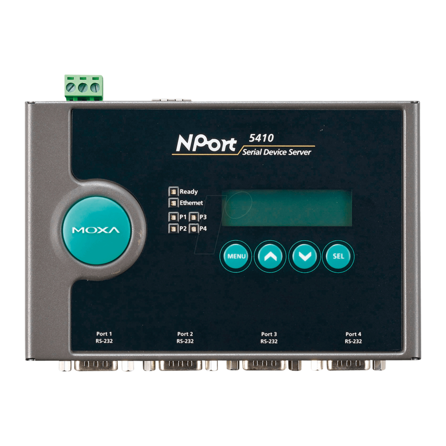
3. Hardware Introduction
As shown in the following figures, NPort 5410 has 4 Male DB9 ports, for
the RS-232 interface, and NPort 5430/5430I has 4 5-pin terminal blocks,
for the RS-422/485 interface.
—1—
—2—
Reset Button—Press the Reset button continuously for 5 sec to load
factory defaults: Use a pointed object, such as a straightened paper clip or
toothpick, to press the reset button. This will cause the Ready LED to
blink on and off. The factory defaults will be loaded once the Ready LED
stops blinking (after about 5 seconds). At this point, you should release
the reset button.
LED Indicators—NPort 5400's top panel contains six LED indicators,
as described in the following table.
LED Name LED Color
LED Function
Steady on: Power is on and NPort is booting up.
Blinking: Indicates an IP conflict, or DHCP
red
or BOOTP server did not respond
properly.
Steady on: Power is on and NPort is
Ready
functioning normally.
green
Blinking: The NPort has been located by
NPort Administrator's Location
function.
off
Power is off, or power error condition exists.
orange
10 Mbps Ethernet connection.
Link
green
100 Mbps Ethernet connection.
off
Ethernet cable is disconnected, or has a short.
orange
Serial port is receiving data.
P1, P2,
green
Serial port is transmitting data.
P3, P4
No data is being transmitted or received through
off
the serial port.
LCM Display Panel—When the NPort 5400 unit is powered up, you will
a see a display similar to:
N
P
5
4
1
0
_
6
1
4
1
9
2
.
1
6
8
.
1
2
This is where NP5410_61405 is the server's name, and 192.168.127.254
is the server's IP address.
LCM Panel Operation—There are four buttons on NPort 5400's top
panel used to operate the server's LCM panel. Going from left to right,
the buttons are:
Button Action
Activates the main menu, or returns to a lower level.
MENU
Scrolls up through a list of items shown on the LCM
panel's second line.
Scrolls down through a list of items shown on the LCM
panel's second line.
Selects the option listed on the LCM panel's second line.
SEL
Detailed LCM Panel Operating instructions can be found on the
CD-ROM in the "NPort 5410/5430/5430I User's Manual."
—3—
0
5
7
.
2
5
4
Advertisement
Table of Contents

Related Manuals for Moxa Technologies Nport 5410


Summary of Contents for Moxa Technologies Nport 5410
- Page 1 LCM Display Panel—When the NPort 5400 unit is powered up, you will 3. Hardware Introduction a see a display similar to: As shown in the following figures, NPort 5410 has 4 Male DB9 ports, for the RS-232 interface, and NPort 5430/5430I has 4 5-pin terminal blocks, for the RS-422/485 interface.
- Page 2 To view detailed information about NPort Administration Suite, click on the Documents button, and then select “NPort 5410/5430/5430I User’s Manual” to open the pdf version of this user’s guide. 6. Pin Assignments and Cable Wiring—NPort 5410 7.
Need help?
Do you have a question about the Nport 5410 and is the answer not in the manual?
Questions and answers