Table of Contents
Advertisement
Quick Links
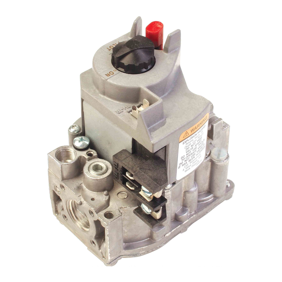
VR8200A
Continuous Pilot
Combination Gas Controls
APPLICATION
These continuous pilot combination gas controls are
used in gas-fired appliances that have up to 200 cfh
capacity of natural gas. They include safety shutoff, a
manual valve, two automatic operators, a standard
pressure regulator and pilot adjustment. Body pattern is
straight-through with 1/2 in. inlet and 1/2 in. outlet.
The VR8200A operates at 24V, 60 Hz and has an
ambient temperature range of 0° F to 175° F [-18° C to
79° C]. The thermostat heat anticipator setting for the
VR8200 is 0.5A. An ECO connector with two 1/4 in quick
connect terminals is available.
The VR8200A package includes:
• Flange Kit 393690-14 with 3/4 in. straight flange and
9/64 in. hex wrench.
• Bushing Kit 390427S with 3/8 in. straight bushing
and pilot compression fitting.
• Q340A 36 in. thermocouple with adapters and clip.
Additional 90° angle and straight flanges are available
for 3/8, 1/2 and 3/4 in. pipe. See Table 1 for flange part
numbers. Flange Kits include one flange with attached
O-ring, four mounting screws and a 9/64 in. hex wrench.
Controls are factory-set for natural (and manufactured)
or LP gas. Do not attempt to use a control set for natural
(manufactured) gas on LP gas, or a control set for LP on
natural (manufactured) gas.
Table 1. Flange Part Numbers
Inlet/Outlet Pipe
Size
Flange Type
3/8 in. NPT
Straight Elbow
1/2 in. NPT
Straight Elbow
3/4 in. NPT
Straight Elbow
a
Elbow (angle) flanges cannot be used to provide a right
hand inlet when the ECO connector is used.
APPROVALS:
American Gas Association design certificate:
UP-70- 57A.
Part No.
393690-11
a
393690-12
393690-16
a
393690-13
393690-14
a
393690-15
INSTALLATION INSTRUCTIONS
Canadian Gas Association design certificate:
1029-CC- 8375.
Australian Gas Association design certificate: 4214.
Approved for Delta C applications.
INSTALLATION
WHEN INSTALLING THIS PRODUCT...
1. Read these instructions carefully. Failure to follow
them could damage the product or cause a haz-
ardous condition.
2. Check the ratings given in the instructions and on
the product to make sure the product is suitable
for your application.
3. Installer must be a trained, experienced service
technician.
4. After installation is complete, check out product
operation as provided in these instructions.
WARNING
FIRE OR EXPLOSION HAZARD CAN CAUSE
PROPERTY DAMAGE, SEVERE INJURY OR
DEATH.
Follow these warnings exactly:
1. Disconnect power supply before wiring to
prevent electrical shock or equipment
damage.
2. To avoid dangerous accumulation of fuel gas,
turn off gas supply at the appliance service
valve before starting installation, and perform
Gas Leak Test after installation is complete.
3. Do not attempt to use a control set for natural
(manufactured) gas on LP gas, or use a
control set for LP on natural (manufactured)
gas.
4. Do not bend pilot tubing at control or pilot
burner after compression fitting has been
tightened, or gas leakage at the connection
may result.
5. Always install sediment trap in gas supply line
to prevent contamination of gas control.
6. Do not force the gas control knob. Use only
your hand to push down the reset button or
turn the gas control knob. Never use any tools.
If the gas control knob or reset button will not
operate by hand, replace the gas control by
using a qualified service technician. Force or
attempted repair may result in fire or
explosion.
69-0421-03
Advertisement
Table of Contents

Subscribe to Our Youtube Channel
Related Manuals for resideo VR8200A


Summary of Contents for resideo VR8200A
- Page 1 WHEN INSTALLING THIS PRODUCT… 1. Read these instructions carefully. Failure to follow The VR8200A operates at 24V, 60 Hz and has an them could damage the product or cause a haz- ambient temperature range of 0° F to 175° F [-18° C to ardous condition.
- Page 2 CONTINUOUS PILOT COMBINATION GAS CONTROLS Complete instructions below for installing piping, CAUTION installing gas control, connecting pilot gas tubing, thermocouple and wiring. Make certain the leak test you perform on the control after completing the installation Never apply a jumper across or short the valve includes leak testing the adapters and screws.
- Page 3 CONTINUOUS PILOT COMBINATION GAS CONTROLS NFPA No. 54), whichever applies. Tubing installation Install Control must comply with approved standards and practices. 1. Mount the gas control 0-90 degrees, in any direc- tion including vertically, from the upright position 1. Use new, properly reamed pipe free from chips. If of the gas control knob.
- Page 4 The Q340A Thermocouple (with adapters) is provided THIS IS AN ELECTRICAL CONNECTION AND MUST BE CLEAN AND DRY. DO NOT USE PIPE COMPOUND. with models of the VR8200A. Install the Q340A as M3095C follows: 1. Determine if the pilot burner requires a thermocou- Fig.
- Page 5 CONTINUOUS PILOT COMBINATION GAS CONTROLS Connect Supplementary Limit or ECO (If used) The leadwires from the high limit or ECO must be equip- ped with insulated 1/4 in. female quick-connect THERMOSTAT HIGH LIMIT CONTROLLER terminals. Leadwire length must not exceed the lengths shown in Tables 3 and 4.
- Page 6 CONTINUOUS PILOT COMBINATION GAS CONTROLS PERFORM GAS LEAK TEST PROPER FLAME ADJUSTMENT WARNING 3/8 TO 1/2 IN. FIRE OR EXPLOSION HAZARD CAN CAUSE (10 TO 13 MM) PROPERTY DAMAGE, SEVERE INJURY, OR DEATH. Check for gas leaks with rich soap and water solution any time work is done on a gas control.
- Page 7 CONTINUOUS PILOT COMBINATION GAS CONTROLS NOTE: Adjustment fitting is plastic and may require IMPORTANT: slightly greater turning force than metal fitting. Allow 60 seconds after shutdown before re- energizing step-opening model to assure ligh- 3. Always replace cap screw. Tighten firmly to prevent toff at step pressure.
- Page 8 Resideo Technologies, Inc. 1985 Douglas Drive North, Golden Valley, MN 55422 1-800-468-1502 69-0421—03 M.S. Rev. 06-20 | Printed in United States www.resideo.com © 2020 Resideo Technologies, Inc. All rights reserved. This product is manufactured by Resideo Technologies, Inc. and its affiliates.
Need help?
Do you have a question about the VR8200A and is the answer not in the manual?
Questions and answers