Table of Contents
Advertisement
Quick Links
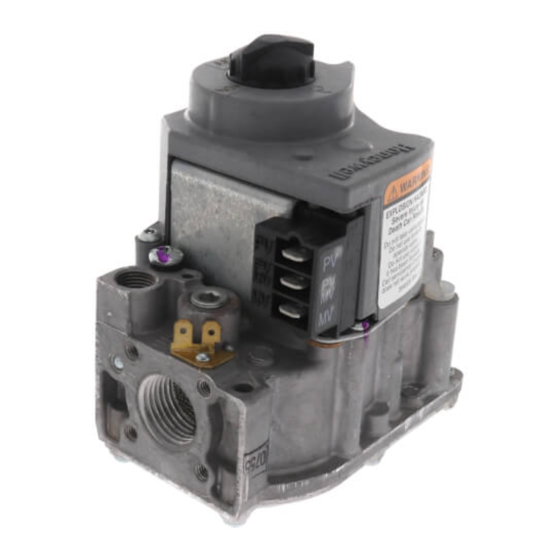
VR8204A,M Intermittent Pilot
Combination Gas Control
APPLICATION
These intermittent pilot gas controls are used in gas-
fired appliances with up to 200 cfh capacity on natural
gas. They include safety shutoff, a manual valve, two
automatic operators, a pressure regulator and a pilot
filter.
Ambient Temperature Range:
VR8204A: 0° F to 175° F [-18° C to 79° C].
VR8204M: -40° F to 175° F [-40° C to 79° C].
Body Pattern:
Straight through with 1/2 in. inlet and 1/2 in. outlet.
Pipe Adapters:
Angle and straight adapters available for 3/8, 1/2, and
3/4 in. pipe. See Table 1. Flange kits include one
flange with attached O-ring, four mounting screws, a
9/64 in. hex wrench and instruction sheet.
Electrical Ratings:
Voltage and frequency: 24 Vac, 60 Hz.
Current draw: 0.5 A with both operators energized.
These gas controls are factory-set for natural (and
manufactured) or LP gas. Do not attempt to use a
control set for natural (manufactured) gas on LP gas, or
a control set for LP on natural (manufactured) gas.
Controls with standard regulators can be converted from
one gas to the other with a conversion kit (order
separately). Order Part No. 393691 to convert from
natural (manufactured) to LP gas; order Part No. 394588
to convert from LP to natural (manufactured) gas.
INSTALLATION INSTRUCTIONS
Approvals
American Gas Association Design Certificate: P-70-42A.
Canadian Gas Association Design Certificate:
1029-CC-6395 series.
Australian Gas Association Certificate: 4214.
Table 1. Adapter (Flange) Part Numbers.
Inlet/Outlet Pipe
Size
Flange Type
3/8 inch NPT
Straight
Elbow
1/2 inch NPT
Straight
Elbow
3/4 inch NPT
Straight
Elbow
NOTE:
Elbow (angle) flanges cannot be used to pro-
vide a right hand inlet when the ECO connector
is used.
INSTALLATION
When Installing this Product...
1. Read these instructions carefully. Failure to follow
them could damage the product or cause a haz-
ardous condition.
2. Check the ratings given in the instructions and on
the product to make sure the product is suitable
for your application.
3. The installer must be a trained, experienced ser-
vice technician.
4. After installation is complete, use these instruc-
tions to check out product operation.
Part Number
393690-11
a
393690-12
393690-16
393690-13
a
393690-14
a
393690-15
69-0423-04
Advertisement
Table of Contents

Subscribe to Our Youtube Channel
Related Manuals for resideo VR8204A


Summary of Contents for resideo VR8204A
- Page 1 Table 1. Adapter (Flange) Part Numbers. Inlet/Outlet Pipe Ambient Temperature Range: Size Flange Type Part Number VR8204A: 0° F to 175° F [-18° C to 79° C]. VR8204M: -40° F to 175° F [-40° C to 79° C]. 3/8 inch NPT Straight 393690-11 393690-12...
- Page 2 VR8204A,M INTERMITTENT PILOT COMBINATION GAS CONTROL Flanges WARNING 1. Choose the appropriate flange for your application. 2. Remove seal over control inlet or outlet. Fire or Explosion Hazard 3. Check to ensure that the O-ring is fitted in the Can cause property damage, severe injury, or groove of the flange.
- Page 3 VR8204A,M INTERMITTENT PILOT COMBINATION GAS CONTROL Install Piping to Gas Control Table 2. NPT pipe thread length in (in.). All piping must comply with local codes and ordinances Thread Pipe Maximum Depth Pipe can or with the National Fuel Gas Code (ANSI Z223.1 NFPA...
- Page 4 VR8204A,M INTERMITTENT PILOT COMBINATION GAS CONTROL WHEN FLANGE IS NOT USED WHEN FLANGE IS USED APPLY WRENCH APPLY WRENCH TO FLANGE ONLY FROM TOP OR BOTTOM OF GAS CONTROL TO EITHER SHADED AREA M2914A Fig. 5. Proper use of wrench on gas control with and without adapters.
- Page 5 VR8204A,M INTERMITTENT PILOT COMBINATION GAS CONTROL LIMIT CONTROLLER (HOT) THERMOSTAT S86 MODULE OR CONTROLLER GAS CONTROL TERMINALS (1) (GND) PV/MV 24V (2) PV/MV AIR PROVING SWITCH (BURNER) COMBUSTION AIR BLOWER RELAY PILOT BURNER GROUND COMBUSTION Q345, Q346, Q348, AIR BLOWER...
- Page 6 VR8204A,M INTERMITTENT PILOT COMBINATION GAS CONTROL Adjust Pilot Flame Standard Pressure Regulator The pilot flame should envelop 3/8 to 1/2 in. [10 to 1. Check the manifold pressure listed on the appli- 13 mm] of the tip of the igniter-sensor. See Fig. 8.
- Page 7 VR8204A,M INTERMITTENT PILOT COMBINATION GAS CONTROL Table 3. Pressure Regulator Specification Pressures in Inches WC. Outlet Pressure Nominal Factory Outlet Setting Adjustment Setting Range Nominal Inlet Model Type of Gas Pressure Range Step Full Rate Step Full Rate Standard Natural 5.0 - 7.0...
- Page 8 Resideo Technologies, Inc. 1985 Douglas Drive North, Golden Valley, MN 55422 1-800-468-1502 69-0423—04 M.S. Rev. 06-20 | Printed in United States www.resideo.com © 2020 Resideo Technologies, Inc. All rights reserved. This product is manufactured by Resideo Technologies, Inc. and its affiliates.
Need help?
Do you have a question about the VR8204A and is the answer not in the manual?
Questions and answers