Table of Contents
Advertisement
Quick Links
V8200A,C,H,M and VR8200A,C,H,M
Continuous Pilot Combination Gas
Controls
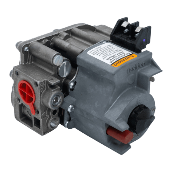
APPLICATION
These continuous pilot combination gas controls are
used in gas-fired appliances up to 200 cfh capacity of
natural gas. They include safety shutoff, a manual valve,
one or two automatic operators, a pressure regulator
and a pilot filter. Body pattern is straight-through with
1/2 in. inlet and 1/2 in. outlet. An ECO connector (part
no. 393200-1) with two 1/4 in. quick connect terminals
is available.
See Table 1 for model differences and Table 2 for
temperature ranges and regulator types.
Additional 90° angle and straight flanges are available
for 3/8, 1/2, and 3/4 in. pipe. See Table 3 for flange part
numbers. Flange kits include one flange with attached
O-ring, four mounting screws, and a 9/64 in. hex wrench.
Model
Frequency
V8200
24 V/60 Hz
VR8200
24 V/60 Hz
Table 2. Model Number Suffix Letter Designation.
Model No.
Ambient
Suffix
Temperature
Letter
A
0° to 175° F (-18° to 79° C)
C
0° to 175° F (-18° to 79° C)
H
0° to 175° F (-18° to 79° C)
M
-40° to 175° F (-40° to 79° C) Standard
Table 1. Continuous Pilot Combination Gas Control Models.
Voltage
Number of
Automatic Operators
Regulator
Range
Standard
Step-opening
Slow-opening
Controls are factory-set for natural (and manufactured)
or LP gas. Do not attempt to use a control set for natural
(manufactured) gas on LP gas, or a control set for LP on
natural (manufactured) gas.
Controls with standard or slow opening regulators can
be converted from one gas to the other with a
conversion kit (order separately). Order Part No. 393691
to convert from natural (manufactured) to LP gas; order
Part No. 394588 to convert from LP to natural
(manufactured) gas. Controls with step opening
regulators cannot be converted.
CSA Certificate: 112395
Australian Gas Association Certificate: 4752
Knob Positions
One
OFF-PILOT-ON
Two
OFF-PILOT-ON
Type
Inlet/Outlet
Pipe Size
3/8 in. NPT
1/2 in. NPT
3/4 in. NPT
a
Elbow (angle) flanges cannot provide right hand inlet
when the ECO connector is used.
NOTE:
INSTALLATION INSTRUCTIONS
Gas Control
Table 3. Flange Part Numbers.
Flange
Type
Straight
NA
393690-2
a
Elbow
Straight
393690-6
393690-3
a
Elbow
Straight
393690-4
393690-5
a
Elbow
Flange Kits include one flange with attached
O-ring and four mounting screws. Kits include
9/64 inch hex wrench, as noted.
Current
Draw
0.30
0.5
Part No.
Less
With
Hex
Hex
Wrench
Wrench
393690-11
NA
NA
393690-13
NA
393690-15
69-0422-05
Advertisement
Table of Contents

Subscribe to Our Youtube Channel
Related Manuals for resideo V8200


Summary of Contents for resideo V8200
- Page 1 Table 1. Continuous Pilot Combination Gas Control Models. Voltage Number of Gas Control Current Model Frequency Automatic Operators Knob Positions Draw V8200 24 V/60 Hz OFF-PILOT-ON 0.30 VR8200 24 V/60 Hz OFF-PILOT-ON Table 2. Model Number Suffix Letter Designation. Table 3. Flange Part Numbers. Model No.
-
Page 2: Installation
3. Installer must be a trained, experienced service To convert a control from natural gas to LP gas, or from LP technician. gas to natural gas, contact your Resideo representative. 4. After installation is complete, check out product operation as provided in these instructions. -
Page 3: Using Adapters To Solve Swing Radius Problems
V8200A,C,H,M AND VR8200A,C,H,M CONTINUOUS PILOT COMBINATION GAS CONTROLS adapters and screws. If you use a wrench on the valve Install Piping to Control after flanges are installed, use the wrench only on the All piping must comply with local codes and ordinances flange, not the control. - Page 4 V8200A,C,H,M AND VR8200A,C,H,M CONTINUOUS PILOT COMBINATION GAS CONTROLS WHEN FLANGE IS NOT USED WHEN FLANGE IS USED APPLY WRENCH APPLY WRENCH TO FLANGE ONLY FROM TOP OR BOTTOM OF GAS CONTROL TO EITHER SHADED AREA M2914A Fig. 5. Proper use of Wrench on Gas Control with and without Flanges. 5.
-
Page 5: Startup And Checkout
V8200A,C,H,M AND VR8200A,C,H,M CONTINUOUS PILOT COMBINATION GAS CONTROLS All wiring must comply with applicable electrical codes Table 6. Maximum Length of Supplementary Limit Lead- and ordinances. wires when using Q309A Thermocouple. Maximum Leadwires Length X 2 Disconnect power supply before making wiring (wires) connections to prevent electrical shock or equipment damage. -
Page 6: Perform Gas Leak Test
V8200A,C,H,M AND VR8200A,C,H,M CONTINUOUS PILOT COMBINATION GAS CONTROLS Perform Gas Leak Test CAUTION Check and Adjust Gas Input to Main Burner WARNING 1. Do not exceed input rating stamped on Fire or Explosion Hazard can cause property appliance nameplate, or manufacturer's damage, severe injury or death. -
Page 7: Check Safety Shutdown Performance
V8200A,C,H,M AND VR8200A,C,H,M CONTINUOUS PILOT COMBINATION GAS CONTROLS 3. If necessary, adjust pressure regulator to match Check Safety Shutdown Performance appliance rating. Refer to Table 7 for factory set nominal outlet pressure and adjustment range. a. Remove pressure regulator adjustment cap WARNING screw. -
Page 8: Instructions To The Homeowner
Resideo Technologies, Inc. 1985 Douglas Drive North, Golden Valley, MN 55422 1-800-468-1502 69-0422—05 M.S. Rev. 11-20 | Printed in United States www.resideo.com © 2020 Resideo Technologies, Inc. All rights reserved. This product is manufactured by Resideo Technologies, Inc. and its affiliates.
Need help?
Do you have a question about the V8200 and is the answer not in the manual?
Questions and answers