
Related Manuals for Emerson Vilter VSG128


Summary of Contents for Emerson Vilter VSG128
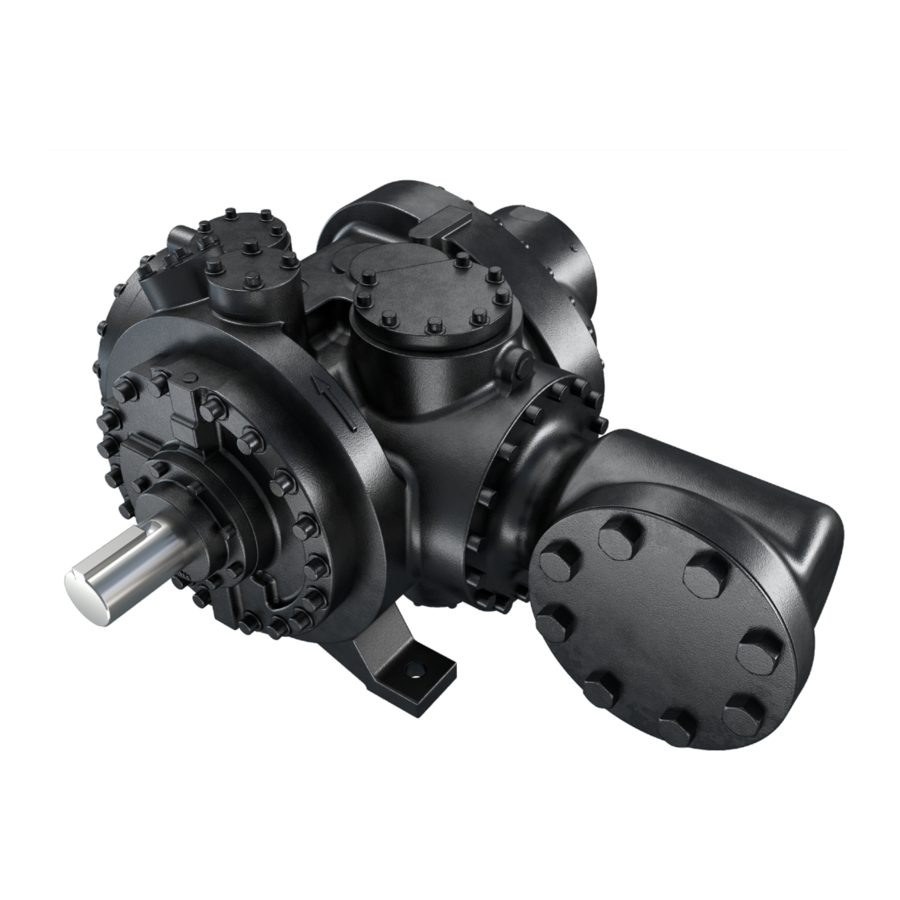
- Page 1 HPLD Single Screw Bare Shaft Compressor Installation, Operation and Service Manual...
-
Page 3: Standard Vilter Warranty Statement
Buyer’s and its customers’ plants and operations. If the Products are for a gas compression application, this warranty does not apply if the Products are operated in conjunction with a gas with an H S level above 100 PPM. HPLD Single Screw Compressor • Installation, Operation and Service Manual • Emerson • 35391HP... - Page 4 Seller will be passed on to those persons who use the Products. Seller’s Products are to be used in their recommended applications and all warning labels adhered to the Products by Seller are to be left intact. HPLD Single Screw Compressor • Installation, Operation and Service Manual • Emerson • 35391HP...
-
Page 5: Important Message
Cudahy, WI 53110-8904 USA Telephone: 1-800-862-2677; Fax:1-414-744-3483 E-mail: info.vilter@emerson.com; Web: Emerson.com/Vilter Equipment Identification Numbers: Vilter Order Number: _______________________Compressor Serial Number: _________________ Vilter Order Number: _______________________Compressor Serial Number: _________________ HPLD Single Screw Compressor • Installation, Operation and Service Manual • Emerson • 35391HP... -
Page 6: Ec Declaration Of Incorporation
EC Declaration of Incorporation We hereby declare that the following machinery is intended to be incorporated into other machinery, and must not be put into service until the relevant machinery into which it is to be incorporated has been declared in con- formity with the essential requirements of the Machinery Directive 2006/42/EC. -
Page 7: Table Of Contents
Operation .............................. 4-1 Control System ............................4-1 Starting, Stopping and Restarting the Compressor ..............4-1 Safety Setpoints .........................4-1 HPLD Control with Vission20/20™ Micro-Controller ................4-2 TOC − 1 HPLD Single Screw Compressor • Installation, Operation and Service Manual • Emerson • 35391HP... - Page 8 Troubleshooting Guide, General Problems and solutions ................ 6-1 Section 7 • Warranty and Parts Warranty Claim Processing ........................7-1 Motor Warranty Procedure ........................7-2 On-Site Service Support ......................... 7-3 TOC − 2 HPLD Single Screw Compressor • Installation, Operation and Service Manual • Emerson • 35391HP...
- Page 9 Tool Kit ............................8-2 Suction Covers ............................8-3 Discharge Manifold ..........................8-4 Housing ..............................8-5 Appendices Appendix A Torque Specifications ......................A-1 Appendix B Vilter Oil .........................B-1 TOC − 3 HPLD Single Screw Compressor • Installation, Operation and Service Manual • Emerson • 35391HP...
- Page 10 Figure 5-22. Tool (A24061A) To Handle Suction Tee Assembly ............... 5-17 Figure 5-23. Tool To Remove Bearing Housing Assembly ................ 5-18 Figure 5-24. Tool To Install and Remove Bearing Housing Assembly............5-18 TOC − 4 HPLD Single Screw Compressor • Installation, Operation and Service Manual • Emerson • 35391HP...
- Page 11 Figure 5-34. Shaft with Pin ........................5-26 Figure 5-35. Shaft Seal Housing......................5-26 Figure 5-36. The Alignment of Compressor Shaft and Mating Ring ............5-26 TOC − 5 HPLD Single Screw Compressor • Installation, Operation and Service Manual • Emerson • 35391HP...
- Page 12 TOC − 6 / Blank HPLD Single Screw Compressor • Installation, Operation and Service Manual • Emerson • 35391HP...
-
Page 13: Section 1 • General Information
NOTE - Notes are shown when there are additional infor- mation pertaining to the instructions explained. 1 – 1 HPLD Single Screw Compressor • Installation, Operation and Service Manual • Emerson • 35391HP... -
Page 14: System Unit Identification
A compressor unit typically a single screw compressor unit, is not mounted on a structural steel base. Package Unit A package unit is a complete system mounted on a structural steel base with interconnecting piping. 1 – 2 HPLD Single Screw Compressor • Installation, Operation and Service Manual • Emerson • 35391HP... -
Page 15: Bare Shaft Hpld Compressor Model Designations
128, 145, 160, 180, 204, 222, 243 C = Ceramic Bearings EO = External Oil Feed VIB = Main Housing with Vibration Mounting N = 900# Flange 1 – 3 HPLD Single Screw Compressor • Installation, Operation and Service Manual • Emerson • 35391HP... - Page 16 1 – 4 / Blank HPLD Single Screw Compressor • Installation, Operation and Service Manual • Emerson • 35391HP...
-
Page 17: Section 2 • Theory Of Operation
VSH160 VSH180 VSH204 VSH222 VSH243 VSS128 VSS145 VSS160 VSS180 VSS204 VSS222 VSS243 DISPLACEMENT AT 3560 RPM (CFM) MAXIMUM ESTIMATED HORSEPOWER AT 3550 RPM 2 – 1 HPLD Single Screw Compressor • Installation, Operation and Service Manual • Emerson • 35391HP... -
Page 18: Capacity And Volume Control
From the discharge manifold, the gas/ oil exits the compressor housing. 2 – 2 HPLD Single Screw Compressor • Installation, Operation and Service Manual • Emerson • 35391HP... -
Page 19: Description Of A Gas System For A Standard Compressor Set
The gas at discharge pressure then exits at the far end of the separator. 2 – 3 HPLD Single Screw Compressor • Installation, Operation and Service Manual • Emerson • 35391HP... -
Page 20: Critical Application Guidelines
Figure 2-1. Basic Single Screw Compressor System 2 – 4 HPLD Single Screw Compressor • Installation, Operation and Service Manual • Emerson • 35391HP... -
Page 21: Procedure For System Pressurization
2-2) with a shut off valve for the operator/technician to use to bring up system pressure (see #1 on Figure 2-2). Figure 2-2. Tubing Line To Pressurize The Unit (Bypassing The Compressor) 2 – 5 HPLD Single Screw Compressor • Installation, Operation and Service Manual • Emerson • 35391HP... -
Page 22: Alarm And Shutdown Readings
2 – 6 HPLD Single Screw Compressor • Installation, Operation and Service Manual • Emerson • 35391HP... -
Page 23: Hpld Package Requirements
2 – 7 HPLD Single Screw Compressor • Installation, Operation and Service Manual • Emerson • 35391HP... - Page 24 2 – 8 / Blank HPLD Single Screw Compressor • Installation, Operation and Service Manual • Emerson • 35391HP...
-
Page 25: Section 3 • Installation
MODEL VSS128 VSS145 VSS160 VSS180 VSS204 VSS222 VSS243 Weight 1095 LBS 1095 LBS 1095 LBS 1090 LBS 1090 LBS 1090 LBS 1090 LBS 3 – 1 HPLD Single Screw Compressor • Installation, Operation and Service Manual • Emerson • 35391HP... -
Page 26: Compressor Inspections Prior To Installation
• If the unit is designed for outdoor duty and is to be stored outdoors, a canvas tarp is recommended for protection until installation. Adequate drainage should be provided. Place wood blocks under the 3 – 2 HPLD Single Screw Compressor •Installation, Operation and Service Manual • Emerson • 35391HP... -
Page 27: Long Term Storage Log
Long Term Storage Log Company: Sales Order Number: Serial Number: Name (Please Print): Initial: Date (M/D/Y): PSI Nitrogen Pressure - Current PSI Nitrogen Pressure - Recharged (If pressure is low, identify and fix leak prior to recharging, see Compressor Unit Leak Check procedure in Section 5) Nitrogen Leak Location (Briefly explain nature of leak): Compressor Shaft (Rotate shafts at least 6 revolutions) -
Page 28: Notice On Using Non-Vilter Oils
3 – 4 HPLD Single Screw Compressor •Installation, Operation and Service Manual • Emerson • 35391HP... -
Page 29: Temperature
If a VFD is used, then amps are fed from the VFD starter to the PLC, therefore a current transformer is not needed. 3 – 5 HPLD Single Screw Compressor • Installation, Operation and Service Manual • Emerson • 35391HP... -
Page 30: Piping
Note this exception: In larger pipe sizes, wrought fittings are not available. However, specially tested cast fittings are available and these may be used with complete safety. 3 – 6 HPLD Single Screw Compressor •Installation, Operation and Service Manual • Emerson • 35391HP... -
Page 31: Testing System For Leaks
If any leaks tion Systems Guide for Subcritical and Transcritical CO are found, they must be repaired and rechecked before plications, by Emerson 3 – 7 HPLD Single Screw Compressor • Installation, Operation and Service Manual • Emerson • 35391HP... - Page 32 3 – 8 / Blank HPLD Compressor Unit • Installation, Operation and Maintenance Manual • Emerson • 35391HPU...
-
Page 33: Section 4 • Operation
When sufficient compressor unit when the discharge temperature oil pressure is built up, the VFD-controlled compressor exceeds the setpoint. motor can start. 4 – 1 HPLD Single Screw Compressor • Installation, Operation and Service Manual • Emerson • 35391HP... -
Page 34: Hpld Control With Vission20/20™ Micro-Controller
Vission20/20™ manual (35391SC). Menu, and then the Model from the next box, see Figure 4-1. FIgure 4-1. Compressor and Model Setup with Vission 20/20 4 – 2 HPLD Single Screw Compressor • Installation, Operation and Service Manual • Emerson • 35391HP... -
Page 35: Section 5 • Maintenance/Service
Section 5 • Maintenance/Service Maintenance and Service Schedule Follow this table for maintaining and servicing the compressor at hourly intervals. 5 – 1 HPLD Single Screw Compressor • Installation, Operation and Service Manual • Emerson • 35391HP... -
Page 36: Recommendations When Servicing
If the high stage refrigeration system is shut off, CO system pressures will gradually rise with the potential to open pressure relief valves & vent excessive CO pressure. 5 – 2 HPLD Single Screw Compressor • Installation, Operation and Service Manual • Emerson • 35391HP... -
Page 37: Oil Sampling
Seek the proper training before proceeding. 5 – 3 HPLD Single Screw Compressor • Installation, Operation and Service Manual • Emerson • 35391HP... -
Page 38: Sampling Procedure
(b) Valve shown ready for oil sampling (c) Valve shown in lockout position Figure 5-3. Oil Sampling Valve (VPN #3709A) For Ammonia and Refrigerant Compressors 5 – 4 HPLD Single Screw Compressor • Installation, Operation and Service Manual • Emerson • 35391HP... -
Page 39: Figure 5-4. Operating The Oil Sampling Valve
This is to pre- vent any accidental release, see Figure 5-3 (c) . Figure 5-5. Stages of the Oil Sample Taking Process 5 – 5 HPLD Single Screw Compressor • Installation, Operation and Service Manual • Emerson • 35391HP... -
Page 40: Oil Sample Analysis Report
• Water content • Viscosity • Acid number • Particle count • Antioxidant level • Wear metals • Contaminating/additive metals 5 – 6 HPLD Single Screw Compressor • Installation, Operation and Service Manual • Emerson • 35391HP... -
Page 41: Compressor Inspection
As a quick reference, Table 5-2 shows the maximum ap- plied forces for 36” lever with 6” pivot for all HPLD com- pressor models. 5 – 7 HPLD Single Screw Compressor • Installation, Operation and Service Manual • Emerson • 35391HP... -
Page 42: Figure 5-7. Bearing Axial Clearance Inspection
Wooden block Position on axis of compressor. or fulcrum Applied Force Small wooden block or fulcrum. Applied Force Figure 5-7. Bearing Axial Clearance Inspection 5 – 8 HPLD Single Screw Compressor • Installation, Operation and Service Manual • Emerson • 35391HP... -
Page 43: C) Gaterotor Bearing Inspection
Force to be determined Rigidly at tach by length of lever arm. dial indicator. Use bolt for fulcrum. Figure 5-8. Gaterotor Bearing Clearance 5 – 9 HPLD Single Screw Compressor • Installation, Operation and Service Manual • Emerson • 35391HP... -
Page 44: Gaterotor Inspection
Gauge Stays Between Must Be Pulled Gaterotor And Shelf Out In This While Rotating Direction Figure 5-10. Gaterotor and Shelf Clearance Measurement Steps 5 – 10 HPLD Single Screw Compressor • Installation, Operation and Service Manual • Emerson • 35391HP... -
Page 45: B) Gaterotor Float Measurement
Vilter Service Department for further assistance. Table 5-4. Gaterotor Float Models Max. Float VSG, VSH, VSS in. (mm) 128, 145, 160, 180, 0.065 204, 222, 243 (1.651) 5 – 11 HPLD Single Screw Compressor • Installation, Operation and Service Manual • Emerson • 35391HP... -
Page 46: C) Gaterotor Backlash Inspection
Figure 5-14. Alignment of Gaterotor Location for Dial Indicator Magnetic Base Gaterotor Support Gaterotor Shelf Figure 5-15. Location of Dial Indicator Magnetic Base 5 – 12 HPLD Single Screw Compressor • Installation, Operation and Service Manual • Emerson • 35391HP... -
Page 47: Table 5-5. Backlash Range
Table 5-5. Fingers Positioning to Move the Gaterotor Back and Forth Displacement Range Figure 5-17. Measuring Backlash 5 – 13 HPLD Single Screw Compressor • Installation, Operation and Service Manual • Emerson • 35391HP... -
Page 48: Important Notes
5 – 14 HPLD Single Screw Compressor • Installation, Operation and Service Manual • Emerson • 35391HP... -
Page 49: Gaterotor Removal And Installation
Discharge Position of rotor before removing the gaterotor/ support assembly Figure 5-19. Rotor Position for Gaterotor/Support Assembly Removal Figure 5-20. Gaterotor/Support Assembly Removal 5 – 15 HPLD Single Screw Compressor • Installation, Operation and Service Manual • Emerson • 35391HP... -
Page 50: Figure 5-21. Gaterotor Assembly
(114), and retainer (109). 7. Remove shim pack (103) and O-ring (104-2). 8. Remove roller bearing housing (105). 9. Remove O-ring (104-3). Figure 5-21. Gaterotor Assembly 5 – 16 HPLD Single Screw Compressor • Installation, Operation and Service Manual • Emerson • 35391HP... -
Page 51: Figure 5-22. Tool (A24061A) To Handle Suction Tee Assembly
MAKE SURE ITEM #103 DO NOT WOBBLE AFTER INSTALLATION. Make sure item #103 do not wobble after installation. Figure 5-22. Tool (A24061A) To Handle Suction Tee Assembly 5 – 17 HPLD Single Screw Compressor • Installation, Operation and Service Manual • Emerson • 35391HP... -
Page 52: Figure 5-23. Tool To Remove Bearing Housing Assembly
Support See Note on tool Figure 5-23. Tool To Remove Bearing Figure 5-24. Tool To Install and Remove Housing Assembly Bearing Housing Assembly 5 – 18 HPLD Single Screw Compressor • Installation, Operation and Service Manual • Emerson • 35391HP... -
Page 53: Installation
Note on NOTE tool This measurement determines the number of shims needed for the correct clearance. Figure 5-25. Tool To Install Bearing Housing Assembly 5 – 19 HPLD Single Screw Compressor • Installation, Operation and Service Manual • Emerson • 35391HP... - Page 54 Check for 0.003 - 0.004” (0.076 - 0.102 mm) clearance between gaterotor blade and partition Figure 5-26. Check the Clearance Between the Gaterotor and Shelf 5 – 20 HPLD Single Screw Compressor • Installation, Operation and Service Manual • Emerson • 35391HP...
-
Page 55: Gaterotor Blade Removal
101.11 101.12 101.13 Figure 5-27. Gaterotor and Support Assembly Top face of gaterotor 101.12a 101.12b Figure 5-28. Gaterotor Top Face Identification 5 – 21 HPLD Single Screw Compressor • Installation, Operation and Service Manual • Emerson • 35391HP... -
Page 56: Gaterotor Ball Bearing Removal
(4 lb-ft), see Figure 5-29. 102.1 102.2 102.3 102.4 Back to Back Arrangement of Bearings Face to Face Arrangement of Bearings Figure 5-29. Gaterotor Ball bearing 5 – 22 HPLD Single Screw Compressor • Installation, Operation and Service Manual • Emerson • 35391HP... -
Page 57: Gaterotor Roller Bearing Removal
(101.1). Once cool, install retaining ring (101.2). 101.3b 101.2 101.3a 101.1 Figure 5-30. Gaterotor Roller Bearing Assembly 5 – 23 HPLD Single Screw Compressor • Installation, Operation and Service Manual • Emerson • 35391HP... -
Page 58: Compressor Shaft Seal Replacement
Be sure to always keep seal faces face-up, rather than face-down, see image on the right. Figure 5-32. Handling Seal Face with Care 5 – 24 HPLD Single Screw Compressor • Installation, Operation and Service Manual • Emerson • 35391HP... -
Page 59: Shaft Seal Removal
(219.4), and O-ring (219.2) out of the seal housing using brass drift and hammer. 8. Remove O-ring (260). Figure 5-33. Shaft Seal Breakdown 5 – 25 HPLD Single Screw Compressor • Installation, Operation and Service Manual • Emerson • 35391HP... -
Page 60: Prior To Shaft Seal Installation (For All Hpld Shaft Seal Models)
Clean compressor shaft and shaft seal cavity in compressor housing. Apply clean compressor lubricating oil to the com- pressor shaft in mating ring seating area, see Figure 5-36. 5 – 26 HPLD Single Screw Compressor • Installation, Operation and Service Manual • Emerson • 35391HP... -
Page 61: Shaft Seal Installation
Figure 5-36. 12. Install the coupling and coupling guard. The unit can then be evacuated and leak checked. Figure 5-33. Shaft Seal Breakdown 5 – 27 HPLD Single Screw Compressor • Installation, Operation and Service Manual • Emerson • 35391HP... -
Page 62: Main Rotor Assembly
* The proof strength of Grade 2 bolts is less for sizes 7/8 and above and therefore the torque values are less than smaller sizes of the same grade. 5 – 28 HPLD Single Screw Compressor • Installation, Operation and Service Manual • Emerson • 35391HP... -
Page 63: Using A Torque Wrench Correctly
This is caused by the washers riding up the opposing ramps. 5 – 29 HPLD Single Screw Compressor • Installation, Operation and Service Manual • Emerson • 35391HP... - Page 64 5 – 30 / Blank HPLD Compressor Unit • Installation, Operation and Maintenance Manual • Emerson • 35391HPU...
-
Page 65: Section 6 • Troubleshooting
• Check cable connections at device, terminal strips, and PLC input card for readings correct wiring and shielding (RF noise). • Check calibration of RTDs and transducers. 6 – 1 HPLD Single Screw Compressor • Installation, Operation and Service Manual • Emerson • 35391HP... - Page 66 • Check for correct fan rotation on the oil cooler. • Check that your operating conditions are within the “As Sold” design conditions. 6 – 2 HPLD Single Screw Compressor • Installation, Operation and Service Manual • Emerson • 35391HP...
- Page 67 • Check condition of compressor and motor (i.e. alignments) • If there is more than normal motor backspin at shutdown, check suction Excessive Motor Backspin check valve for proper operation. 6 – 3 HPLD Single Screw Compressor • Installation, Operation and Service Manual • Emerson • 35391HP...
- Page 68 6 – 4 / Blank HPLD Compressor Unit • Installation, Operation and Maintenance Manual • Emerson • 35391HPU...
-
Page 69: Section 7 • Warranty And Parts
STEP 2. Return the parts (freight prepaid) to: assist with the OEM to determine the part/product’s warranty status. VILTER MANUFACTURING CORPORATION 5555 South Packard Avenue Cudahy, WI 53110-8904 7 – 1 HPLD Single Screw Compressor • Installation, Operation and Service Manual • Emerson • 35391HP... - Page 70 Section 7 • Warranty and Parts 7 – 2 HPLD Single Screw Compressor • Installation, Operation and Service Manual • Emerson • 35391HP...
-
Page 71: On-Site Service Support
• Send the compressor to Vilter in the condition as stated on the Rebuild Form (i.e. no oil in the compres- sor). Charges may apply if conditions are not met. 7 – 3 HPLD Single Screw Compressor • Installation, Operation and Service Manual • Emerson • 35391HP... - Page 72 7 – 4 / Blank HPLD Compressor Unit • Installation, Operation and Maintenance Manual • Emerson • 35391HPU...
-
Page 73: Section 8 • Spare Parts List
Spare Parts Section for Specific Applications Please have your Model # and Sales Order # available when ordering. These are found on the compressor’s Name Plate. 8 – 1 HPLD Single Screw Compressor • Installation, Operation and Service Manual • Emerson • 35391HP... -
Page 74: Hpld Compressor Kits
KT713ABFAF* KT712ABFV** KT713ABFV** Gaterotor A25205G For Gaterotor Tool Kit Removal and KT712ABGAF* KT713ABGAF* Suction Tee Installation A24061A KT712ABGV** KT713ABGV** Tool Kit *Aflas **Viton 8 – 2 HPLD Single Screw Compressor • Installation, Operation and Service Manual • Emerson • 35391HP... -
Page 75: Suction Covers
QUANTITY SCREEN 205MM SUCTION 25920A RING 4.500X0.109 RETAINING INT BEVELED 2867AS O-RING 8.484 X 8.762 AFLAS VP101 3547AD SPRING SSB0433 WAVE SMALLEY 2912G 8 – 3 HPLD Single Screw Compressor • Installation, Operation and Service Manual • Emerson • 35391HP... -
Page 76: Discharge Manifold
Discharge Manifold Components MODELS VSG/VSH/VSS128 to VSG/VSH/VSS243 ITEM DESCRIPTION QUANTITY O-RING 11.984 X 12.262 AFLAS VP101 3547AA O-RING 3.484 X 3.762 AFLAS VP101 3547AB 8 – 4 HPLD Single Screw Compressor • Installation, Operation and Service Manual • Emerson • 35391HP... -
Page 77: Housing
PLUG 1/4-18NPTF FLUSH SEAL SOC HD 2606C PLUG 5/16 HEX SAE FOR J1926 PORT AFLAS 3647A PLUG 9/16 HEX SAE FOR J1926 PORT AFLAS 3647D 8 – 5 HPLD Single Screw Compressor • Installation, Operation and Service Manual • Emerson • 35391HP... - Page 78 8 − 6 / Blank HPLD Compressor Unit • Installation, Operation and Maintenance Manual • Emerson • 35391HPU...
-
Page 79: Appendix A Torque Specifications
Continue use of red loctite #271 (VPN 2205E) on currently applied locations. Use blue loctite #243 (VPN 2205F or 2205G) on all remaining locations. A − 1 HPLD Single Screw Compressor • Installation, Operation and Service Manual • Emerson • 35391HP... - Page 80 A − 2 / Blank HPLD Single Screw Compressor • Installation, Operation and Service Manual • Emerson • 35391HP...
-
Page 81: Appendix B Vilter Oil
Appendix B • Vilter Oil Oil Analysis Report B − 1 HPLD Single Screw Compressor • Installation, Operation and Service Manual • Emerson • 35391HP... - Page 82 B − 2 / Blank HPLD Single Screw Compressor • Installation, Operation and Service Manual • Emerson • 35391HP...
- Page 84 Vilter Manufacturing LLC reserves the right to make changes in design and specifications without notice. 35391HP Rev. 01(06/21) Emerson and Vilter are trademarks of Emerson Electric Co. or one of its affiliated companies. ©2021 Emerson Climate Technologies, Inc. All rights reserved.
Need help?
Do you have a question about the Vilter VSG128 and is the answer not in the manual?
Questions and answers