
Related Manuals for Emerson VILTER VSG


Summary of Contents for Emerson VILTER VSG
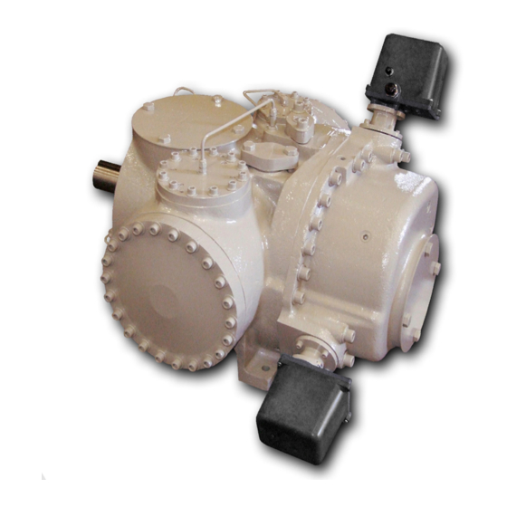
- Page 1 VSG & VSSG Single Screw Bare Shaft Compressor Installation, Operation and Service Manual The World's Best Compressors For Gas Compression...
-
Page 3: Important Message
Telephone: 1-800-862-2677, Fax:1-414-744-3483 E-mail: info.vilter@emerson.com, Website: Emerson.com/Vilter Equipment Identification Numbers: Vilter Order Number: _______________________Compressor Serial Number: _________________ Vilter Order Number: _______________________Compressor Serial Number: _________________ VSG & VSSG Single Screw Compressor • Installation, Operation and Service Manual • Emerson • 35391SB... -
Page 4: Vsg Standard Vilter Warranty Statement
Seller or Seller’s agents regarding use, application or suitability of the products shall not be construed as an express warranty unless confirmed to be such in writing by Seller. VSG & VSSG Single Screw Compressor • Installation, Operation and Service Manual • Emerson • 35391SB... - Page 5 Regulatory Compliance Department: europeproductcompliance@emerson.com (+40 374 132 000). In Great Britain, it is Emerson Process Management Ltd., Company No 00671801, Meridian East, Leicester, LE19 1UX, United Kingdom. For product compliance destination sales questions contact the Regulatory Compliance Department: ukproductcompliance@emerson.com...
- Page 6 / Blank VSG & VSSG Single Screw Compressor • Installation, Operation and Service Manual • Emerson • 35391SB...
-
Page 7: Table Of Contents
Installation and Calibration of Slide Valve Actuators ................3-13 Slide Valve Actuator Installation Instructions ................3-13 Actuator Motor Control Module Calibration Procedure ............... 3-13 Slide Valve Operation ..........................3-15 TOC − 1 VSG & VSSG Single Screw Compressor • Installation, Operation and Service Manual • Emerson • 35391SB... - Page 8 Slide Valve Command Shaft Bearing and O-Ring Seal Replacement (For the Design Before June 2006) ... 5-20 Removal .............................5-20 Reassembly ..........................5-21 TOC − 2 VSG & VSSG Single Screw Compressor • Installation, Operation and Service Manual • Emerson • 35391SB...
- Page 9 VSG 301-701 Replacement Parts Section ....................8-27 Gaterotor Assembly ........................8-28 Shaft Seal ...........................8-31 Main Rotor, Slide Valve Cross Shafts and End Plate ..............8-32 TOC − 3 VSG & VSSG Single Screw Compressor • Installation, Operation and Service Manual • Emerson • 35391SB...
- Page 10 Replacement Tools ........................8-44 Appendices Appendix A Torque Specifications ......................A-1 Appendix B Vilter Oil .........................B-1 Appendix C Vibration Measurements - Single Screw Compressor............C-1 TOC − 4 VSG & VSSG Single Screw Compressor • Installation, Operation and Service Manual • Emerson • 35391SB...
- Page 11 Figure 4-7. Slide Calibration Screen (Compact Logix PLC) ............... 4-9 Figure 4-8. Photo-chopper ........................4-9 Figure 5-1. Bearing Axial Clearance Inspection ..................5-3 TOC − 5 VSG & VSSG Single Screw Compressor • Installation, Operation and Service Manual • Emerson • 35391SB...
- Page 12 Figure 5-18. Compressor Shaft Seal Installation..................5-14 Figure 5-19. Actuator Installation Using Anti-Rotation Bolts ..............5-18 Figure 5-20. Command Shaft Assembly Replacement ................5-19 TOC − 6 VSG & VSSG Single Screw Compressor • Installation, Operation and Service Manual • Emerson • 35391SB...
-
Page 13: Section 1 • General Information
Figures and tables are included to illustrate key concepts. made to Vilter Manufacturing at the contact infor- mation on page i. 1 – 1 VSG & VSSG Single Screw Compressor • Installation, Operation and Service Manual • Emerson • 35391SB... -
Page 14: Bare Shaft Gas Compressor Model Designations
N - 900# Flange bet of slide number used in compres- sor BOM. AF - Aflas O-rings LT - 205mm LITE compressor 1 – 2 VSG & VSSG Single Screw Compressor • Installation, Operation and Service Manual • Emerson • 35391SB... -
Page 15: System Unit Identification
A compressor unit typically a single screw compressor unit, is not mounted on a structural steel base. Package Unit A package unit is a complete system mounted on a structural steel base with interconnecting piping. 1 – 3 VSG & VSSG Single Screw Compressor • Installation, Operation and Service Manual • Emerson • 35391SB... -
Page 16: Table 1-1. Vsg Standard Materials Of Construction
ASTM A-126 Slide Valve Drive Shafts Steel ASTM A-108 Bearings Cylindrical Roller Type Bearings Angular Contact Ball Bearing Cages Steel & Polyamide 1 – 4 VSG & VSSG Single Screw Compressor • Installation, Operation and Service Manual • Emerson • 35391SB... -
Page 17: Section 2 • Theory Of Operation
10% of the full rated capacity. rotor tooth in the groove, and to lubricate the moving parts. 2 – 1 VSG & VSSG Single Screw Compressor • Installation, Operation and Service Manual • Emerson • 35391SB... -
Page 18: Description Of A Gas System For A Standard Compressor Set
1.2 up to 7.0. up from the process gas, and is injected back into the compressor. 2 – 2 VSG & VSSG Single Screw Compressor • Installation, Operation and Service Manual • Emerson • 35391SB... -
Page 19: Description Of An Oil System For A Standard Compressor Set
RTD located in the compressor discharge manifold. 2 – 3 VSG & VSSG Single Screw Compressor • Installation, Operation and Service Manual • Emerson • 35391SB... - Page 20 (oil filter outlet pressure) reading. 2 – 4 VSG & VSSG Single Screw Compressor • Installation, Operation and Service Manual • Emerson • 35391SB...
-
Page 21: Vsg Package Requirements
Figure 2-1. Basic Single Screw Compressor System 2 – 5 VSG & VSSG Single Screw Compressor • Installation, Operation and Service Manual • Emerson • 35391SB... - Page 22 2 – 6 / Blank VSG & VSSG Single Screw Compressor • Installation, Operation and Service Manual • Emerson • 35391SB...
-
Page 23: Section 3 • Installation
A log should be maintained indicating that the above procedures have been completed. 3 – 1 VSG & VSSG Single Screw Compressor • Installation, Operation and Service Manual • Emerson • 35391SB... -
Page 24: Long Term Storage Log
Long Term Storage Log Company: Serial Number: Sales Order Number: Name (Please Print): Initial: Date (M/D/Y): PSIG Nitrogen Pressure - Current PSIG Nitrogen Pressure - Recharged (If pressure is low, identify and fix leak prior to recharging, see Compressor Unit Leak Check procedure in Section 5 of the compressor manual) Nitrogen Leak Location (Briefly explain nature of leak): Compressor Shaft (Rotate shafts at least 6 revolutions) -
Page 25: Instrumentation Requirements
3 – 3 VSG & VSSG Single Screw Compressor • Installation, Operation and Service Manual • Emerson • 35391SB... -
Page 26: Figure 3-1. Additional Instruments
OPTIONAL DUAL OIL FILTERS VENT OIL COOLER DRAIN DRAIN STANDARD WATER COOLED OIL COOLER OPTIONAL REMOTE AIR COOLED OIL COOLER Figure 3-1. Additional Instruments 3 – 4 VSG & VSSG Single Screw Compressor • Installation, Operation and Service Manual • Emerson • 35391SB... -
Page 27: Piping
A second method would be to install flexible pipe cou- plings as close to the compressor unit as possible with connections run in two different directions, 90° apart. 3 – 5 VSG & VSSG Single Screw Compressor • Installation, Operation and Service Manual • Emerson • 35391SB... -
Page 28: Figure 3-2. Single Compressor Suction Piping
Section 3 • Installation Figure 3-2. Single Compressor Suction Piping Figure 3-3. Multiple Compressor Suction Piping 3 – 6 VSG & VSSG Single Screw Compressor • Installation, Operation and Service Manual • Emerson • 35391SB... -
Page 29: Compressor Discharge Piping
Table 3-1. Figure 3-5. Single Compressor Discharge Piping Figure 3-4. Multiple Compressor Suction Piping (Where Drain Back to Accumulator Is Not Possible) 3 – 7 VSG & VSSG Single Screw Compressor • Installation, Operation and Service Manual • Emerson • 35391SB... -
Page 30: Figure 3-6. Multiple Compressor Discharge Piping, Vertical To System
Section 3 • Installation Figure 3-6. Multiple Compressor Discharge Piping, Vertical To System Figure 3-7. Multiple Compressor Discharge Piping, Horizontal to System With Options 3 – 8 VSG & VSSG Single Screw Compressor • Installation, Operation and Service Manual • Emerson • 35391SB... -
Page 31: Oil Line And Aftercooler Piping
Figure 3-8. Compressor Oil Line piping to Air-Cooled Oil Cooler Figure 3-9. Aftercooler Piping 3 – 9 VSG & VSSG Single Screw Compressor • Installation, Operation and Service Manual • Emerson • 35391SB... -
Page 32: Air Cooled Condenser Piping
2 through 4 Larger than 4 Figure 3-10. Single Refrigeration Air-Cooled Condenser Piping Figure 3-11. Refrigeration Multiple Air Cooled Condenser Piping 3 – 10 VSG & VSSG Single Screw Compressor • Installation, Operation and Service Manual • Emerson • 35391SB... -
Page 33: Allowable Flange Loads
VALVE SUPPORT CUSTOMER SUPPORTS WHEN CHECK VALVE CHECK IS MOUNTED HERE VALVE CUSTOMER CUSTOMER SUPPORT SUPPORT Figure 3-12. Piping Elements Support 3 – 11 VSG & VSSG Single Screw Compressor • Installation, Operation and Service Manual • Emerson • 35391SB... -
Page 34: Testing System For Leaks
3 – 12 VSG & VSSG Single Screw Compressor • Installation, Operation and Service Manual • Emerson • 35391SB... -
Page 35: Installation And Calibration Of Slide Valve Actuators
See Table 4-1 on page for This prevents the DC position transmitter cable Actuator/command shaft rotation specifications. from picking up electrical noise from the AC power 3 – 13 VSG & VSSG Single Screw Compressor • Installation, Operation and Service Manual • Emerson • 35391SB... - Page 36 The red LED will stop flashing. The actuator is now calibrated and knows the minimum and maximum positions of the slide 3 – 14 VSG & VSSG Single Screw Compressor • Installation, Operation and Service Manual • Emerson • 35391SB...
-
Page 37: Slide Valve Operation
EEPROM memory. When power is restored, the 3 – 15 VSG & VSSG Single Screw Compressor • Installation, Operation and Service Manual • Emerson • 35391SB... - Page 38 3 – 16 / Blank VSG & VSSG Single Screw Compressor • Installation, Operation and Service Manual • Emerson • 35391SB...
-
Page 39: Section 4 • Operation
6. Discharge Temperature The high discharge temperature cutout stops the com- pressor unit when the discharge temperature exceeds the setpoint. 4 – 1 VSG & VSSG Single Screw Compressor • Installation, Operation and Service Manual • Emerson • 35391SB... -
Page 40: Control System
Solutions in Section 6. If the compressor is in the automatic mode, it will now load and unload in response to the system demands. 4 – 2 VSG & VSSG Single Screw Compressor • Installation, Operation and Service Manual • Emerson • 35391SB... -
Page 41: Slide Valve Actuator Calibration (25972Xp)
Do not over tighten screws. Failure to comply may assembly. As a reference see Figure 4-3. result in damage to equipment. Carefully lift actuator cover from actuator assembly. 4 – 3 VSG & VSSG Single Screw Compressor • Installation, Operation and Service Manual • Emerson • 35391SB... -
Page 42: Figure 4-1. Slide Calibration Screen (Not In Calibration Mode)
(5% or below) for pre-start-up. Figure 4-1. Slide Calibration Screen (Not in Calibration Mode) 4 – 4 VSG & VSSG Single Screw Compressor • Installation, Operation and Service Manual • Emerson • 35391SB... -
Page 43: Figure 4-2. Slide Calibration Screen (In Calibration Mode)
Look Gear Visible Inside to Check Rotation Figure 4-3. Actuator Inside Figure 4-4. Rotation Check. Motor/Brake Shaft Spins Opposite of the Command Shaft 4 – 5 VSG & VSSG Single Screw Compressor • Installation, Operation and Service Manual • Emerson • 35391SB... -
Page 44: Slide Valve Actuators Calibration (For Vpn 25972D Only)
Figure 4-7. View Rotate 180° Actuator Assembly Actuator Plastic Cover Red LED Blue Calibrate Button Figure 4-5. Actuator Assembly 4 – 6 VSG & VSSG Single Screw Compressor • Installation, Operation and Service Manual • Emerson • 35391SB... - Page 45 3 seconds to pulse the actuator to where the slide is just off of the mechanical stop and there is no tension on the motor shaft. 4 – 7 VSG & VSSG Single Screw Compressor • Installation, Operation and Service Manual • Emerson • 35391SB...
-
Page 46: Figure 4-6. Overview, Main Menu And Instrument Calibration Screens (Compact Logix Plc)
Section 4 • Operation Figure 4-6. Overview, Main Menu and Instrument Calibration Screens (Compact Logix PLC) 4 – 8 VSG & VSSG Single Screw Compressor • Installation, Operation and Service Manual • Emerson • 35391SB... -
Page 47: Figure 4-7. Slide Calibration Screen (Compact Logix Plc)
Figure 4-7. Slide Calibration Screen (Compact Logix PLC) Press down on Photo-chopper to release tension from motor shaft. Figure 4-8. Photo-chopper 4 – 9 VSG & VSSG Single Screw Compressor • Installation, Operation and Service Manual • Emerson • 35391SB... -
Page 48: Table 4-1. Command Shaft Rotation Specifications
The shaft should be centered in its travel. Do not use excessive force manually operating the motor or damage may result. 4 – 10 VSG & VSSG Single Screw Compressor • Installation, Operation and Service Manual • Emerson • 35391SB... -
Page 49: Section 5 • Maintenance/Service
Section 5 • Maintenance/Service Maintenance and Service Schedule Follow this table for maintaining and servicing the compressor unit at hourly intervals. 5 – 1 VSG & VSSG Single Screw Compressor • Installation, Operation and Service Manual • Emerson • 35391SB... -
Page 50: Additional Notes
Oil Separator. More than this will reflect a faulty Suction Check Valve or Open Bleed line around the Suction Check Valve, which should be closed dur- ing operation. 5 – 2 VSG & VSSG Single Screw Compressor • Installation, Operation and Service Manual • Emerson • 35391SB... -
Page 51: Compressor Inspection
The maximum amount of bearing float should not exceed 0.002”. 5 – 3 VSG & VSSG Single Screw Compressor • Installation, Operation and Service Manual • Emerson • 35391SB... -
Page 52: Table 5-3. Gate Rotor Float
0.060 (1.524) E. Readings could be higher than 0.020. If readings is greater than 0.030 over table tolerance contact Vilter’s home office. 5 – 4 VSG & VSSG Single Screw Compressor • Installation, Operation and Service Manual • Emerson • 35391SB... -
Page 53: Gaterotor Assembly Replacement
Turn the jacking screw clockwise. The thrust bearings and housing assem- bly will be pulled off the shaft and out of the frame. 5 – 5 VSG & VSSG Single Screw Compressor • Installation, Operation and Service Manual • Emerson • 35391SB... -
Page 54: Removal (All Vsg 301-701 Models)
The compressor input shaft may 5 – 6 VSG & VSSG Single Screw Compressor • Installation, Operation and Service Manual • Emerson • 35391SB... - Page 55 Section 5 • Maintenance/Service Figure 5-7. Gaterotor Assembly Breakdown 5 – 7 VSG & VSSG Single Screw Compressor • Installation, Operation and Service Manual • Emerson • 35391SB...
-
Page 56: Installation (All Vsg Models)
Make adjustments, if necessary. It is preferable to shim the gate rotor blade looser rather than tighter against the shelf. Figure 5-8. Gaterotor Thrust Bearing 5 – 8 VSG & VSSG Single Screw Compressor • Installation, Operation and Service Manual • Emerson • 35391SB... - Page 57 Section 5 • Maintenance/Service Figure 5-10. Gaterotor and Shelf Clearance Figure 5-9. Gaterotor Assembly and Tools 5 – 9 VSG & VSSG Single Screw Compressor • Installation, Operation and Service Manual • Emerson • 35391SB...
-
Page 58: Installation (All Vsg 301-701 Models)
3. Figure 5-12. Gaterotor Blade Assembly Figure 5-11. Gaterotor and Shelf Clearance Gaterotor for C-flange Models 5 – 10 VSG & VSSG Single Screw Compressor • Installation, Operation and Service Manual • Emerson • 35391SB... -
Page 59: Gate Rotor Blade Removal
INSTALLATION (All VSG Models). Figure 5-13. Gaterotor Blade Installation For installation of the gate rotor assembly and 5 – 11 VSG & VSSG Single Screw Compressor • Installation, Operation and Service Manual • Emerson • 35391SB... -
Page 60: Gate Rotor Roller Bearing Removal
INSTALLATION (All VSG Models). Inner Retainer Figure 5-16. Roller Bearing Assembly Ball Bearings Retaining Ring Figure 5-15. Thrust Bearing Installation 5 – 12 VSG & VSSG Single Screw Compressor • Installation, Operation and Service Manual • Emerson • 35391SB... -
Page 61: Compressor Shaft Seal Replacement
A spray bottle filled with clean compressor oil may be Carbon Component used to lubricate the faces of the seals without touching the seal. Figure 5-17. Compressor Shaft Seal 5 – 13 VSG & VSSG Single Screw Compressor • Installation, Operation and Service Manual • Emerson • 35391SB... - Page 62 Install the coupling and coupling guard. The unit can then be evacuated and leak checked. Figure 5-18. Compressor Shaft Seal Installation 5 – 14 VSG & VSSG Single Screw Compressor • Installation, Operation and Service Manual • Emerson • 35391SB...
-
Page 63: Inspection Of Slide Valve Assemblies In The Compressor
If the slide valves are worn in excess of the tolerances, of assembly. the factory should be contacted. Feeler gauge Measure Here Check for wear in these areas. 5 – 15 VSG & VSSG Single Screw Compressor • Installation, Operation and Service Manual • Emerson • 35391SB... -
Page 64: Installation Of Slide Valve Carriage Assemblies
Lock washers beneath the heads, but do not tighten them. Work a piece of 0.005”shim stock between the slide valves and the main rotor to help position the carriage. 5 – 16 VSG & VSSG Single Screw Compressor • Installation, Operation and Service Manual • Emerson • 35391SB... -
Page 65: Slide Valve Actuator Assembly Replacement
Washes that securing actuator assembly to ac- tuator mount. See Figure 5-19 for parts details. Remove actuator assembly from actuator mount. 5 – 17 VSG & VSSG Single Screw Compressor • Installation, Operation and Service Manual • Emerson • 35391SB... -
Page 66: Actuator Installation Using Anti-Rotation Bolts
(b) Locking Retainer (a) Groove bolt and washer Complete Assembly E- clip (C) E-clip Figure 5-19. Actuator Installation Using Anti-Rotation Bolts 5 – 18 VSG & VSSG Single Screw Compressor • Installation, Operation and Service Manual • Emerson • 35391SB... - Page 67 Align the tongue of the command shaft with the groove in the cross shaft Figure 5-20. Command Shaft Assembly Replacement 5 – 19 VSG & VSSG Single Screw Compressor • Installation, Operation and Service Manual • Emerson • 35391SB...
-
Page 68: Slide Valve Command Shaft Assembly Replacement
436) might have to be removed to gain access to O-rings. Replace bushing if the bore is deeply scored or excessively worn. 5 – 20 VSG & VSSG Single Screw Compressor • Installation, Operation and Service Manual • Emerson • 35391SB... -
Page 69: Reassembly
Therefore, remove manifold straight back approximately 1” as not to break dowel pins. Guide rods Discharge spoo NOTE 5 – 21 VSG & VSSG Single Screw Compressor • Installation, Operation and Service Manual • Emerson • 35391SB... -
Page 70: Slide Valve Gear And Rack Inspection
VSG 751-2101 compressors cross shafts. Reassemble the manifold and discharge elbow. VSSG 291-601 compressors cross shafts Volume control cross shaft. 5 – 22 VSG & VSSG Single Screw Compressor • Installation, Operation and Service Manual • Emerson • 35391SB... -
Page 71: Installation Of Capacity Or Volume Cross Shafts
Install washers and jam nuts on the slide valve shafts. Repeat the procedure for the remain- ing set of slide valve racks. 5 – 23 VSG & VSSG Single Screw Compressor • Installation, Operation and Service Manual • Emerson • 35391SB... -
Page 72: Main Rotor Assembly
* The proof strength of Grade 2 bolts is less for sizes 7/8 and above and therefore the torque values are less than smaller sizes of the same grade. 5 – 24 VSG & VSSG Single Screw Compressor • Installation, Operation and Service Manual • Emerson • 35391SB... -
Page 73: Using A Torque Wrench Correctly
Mate Together to tighten it. This is caused by the washers rid- ing up the opposing ramps. 5 – 25 VSG & VSSG Single Screw Compressor • Installation, Operation and Service Manual • Emerson • 35391SB... - Page 74 5 – 26 / Blank VSG & VSSG Single Screw Compressor • Installation, Operation and Service Manual • Emerson • 35391SB...
-
Page 75: Section 6 • Troubleshooting
The position sensor’s EEPROM Replace the actuator. memory has failed 6 – 1 VSG & VSSG Single Screw Compressor • Installation, Operation and Service Manual • Emerson • 35391SB... -
Page 76: Table 6-1. Slide Valve Actuator Troubleshooting Guide (2 Of 2)
The motor runs but output shaft will motor or the armature has come un- Replace the actuator. not turn pressed from the armature shaft 6 – 2 VSG & VSSG Single Screw Compressor • Installation, Operation and Service Manual • Emerson • 35391SB... -
Page 77: Slide Valve Actuator Led Blink Codes
TP1 and TP2 are plated-thru holes located close to the slotted optocouplers on the board. They are clearly marked on the board silkscreen legend. 6 – 3 VSG & VSSG Single Screw Compressor • Installation, Operation and Service Manual • Emerson • 35391SB... -
Page 78: Table 6-2. Slide Valve Actuator Led Blink Codes (2 Of 2)
(2) The TS1 wire pads are where the motor thermal switch leads solder into the circuit board. They are clearly marked on the board silkscreen legend and are oriented at a 45 degree angle. 6 – 4 VSG & VSSG Single Screw Compressor • Installation, Operation and Service Manual • Emerson • 35391SB... -
Page 79: Troubleshooting Guide - General Problems And Solutions
• Check cable connections at device, terminal strips, and PLC input card for correct ture readings wiring and shielding (RF noise). • Check calibration of RTDs and transducers. 6 – 5 VSG & VSSG Single Screw Compressor • Installation, Operation and Service Manual • Emerson • 35391SB... -
Page 80: Table 6-3. Troubleshooting Guide - General Problems And Solutions (2 Of 3)
• Reference Slide Valve Actuator Troubleshooting Guide • Check I/O fusing High Amp Draw • Check Main Motor Amps scaling and PLC. 6 – 6 VSG & VSSG Single Screw Compressor • Installation, Operation and Service Manual • Emerson • 35391SB... -
Page 81: Table 6-3. Troubleshooting Guide - General Problems And Solutions (3 Of 3)
• If there is more than normal motor backspin at shutdown, check suction check Excessive Motor Backspin valve for proper operation. 6 – 7 VSG & VSSG Single Screw Compressor • Installation, Operation and Service Manual • Emerson • 35391SB... - Page 82 6 – 8 / Blank VSG & VSSG Single Screw Compressor • Installation, Operation and Service Manual • Emerson • 35391SB...
-
Page 83: Section 7 • Warranty And Parts
5555 South Packard Avenue to ascertain additional information and will reasonably Cudahy, WI 53110-8904 assist with the OEM to determine the part/product’s warranty status. 7 – 1 VSG & VSSG Single Screw Compressor • Installation, Operation and Service Manual • Emerson • 35391SB... - Page 84 7 – 2 VSG & VSSG Single Screw Compressor • Installation, Operation and Service Manual • Emerson • 35391SB...
-
Page 85: On-Site Service Support
• A report will be sent to you after the inspection has been completed explaining what level of rebuild is necessary along with the cost. NOTE 7 – 3 VSG & VSSG Single Screw Compressor • Installation, Operation and Service Manual • Emerson • 35391SB... - Page 86 7 – 4 / Blank VSG & VSSG Single Screw Compressor • Installation, Operation and Service Manual • Emerson • 35391SB...
-
Page 87: Section 8 • Spare Parts List
DOWEL PIN, LG, 0.4375” 135B 25910A O.D. VPN A25159BB - SUPPORT ASSEMBLY includes items (110 and 135B). Terms and Abbreviation Used 8 − 1 VSG & VSSG Single Screw Compressor • Installation, Operation and Service Manual • Emerson • 35391SB... - Page 88 8 − 2 / Blank VSG & VSSG Single Screw Compressor • Installation, Operation and Service Manual • Emerson • 35391SB...
-
Page 89: Recommended Spare Parts List
NOTE Please have your Model # and Sales Order # available when ordering. These are found on the compressor’s Name Plate. 8 − 3 VSG & VSSG Single Screw Compressor • Installation, Operation and Service Manual • Emerson • 35391SB... -
Page 90: Gate Rotor
Section 8 • Spare Parts List Gate Rotor 8 − 4 VSG & VSSG Single Screw Compressor • Installation, Operation and Service Manual • Emerson • 35391SB... - Page 91 HEX HEAD CAP SCREW 2796CJ 2796CJ HEX HEAD CAP SCREW 2796E 2796E SOCKET HEAD CAP SCREW 2795E 2795E Note- AR - As Required. 8 − 5 VSG & VSSG Single Screw Compressor • Installation, Operation and Service Manual • Emerson • 35391SB...
- Page 92 O-RING BALL BRG HSG 2825X 2825X 2825AC 2825AC O-RING BRG HSG COVER 2825T 2825T 2825T 2825T Note- AR - As Required. 8 − 6 VSG & VSSG Single Screw Compressor • Installation, Operation and Service Manual • Emerson • 35391SB...
- Page 93 HEX HEAD CAP SCREW 2796CJ 2796CJ 2796CJ HEX HEAD CAP SCREW 2796R 2796R 2796R SOCKET HEAD CAP SCREW 2795G 2795G 2795G 8 − 7 VSG & VSSG Single Screw Compressor • Installation, Operation and Service Manual • Emerson • 35391SB...
-
Page 94: Shaft Seal
VSG 1551 - 2101 SHAFT SEAL VITON KIT (219, 260, 230) KT709AG KT709BG KT709CG OIL SEAL 25040A 2930F 2930B O-RING 2825F 2825AR 2825W 8 − 8 VSG & VSSG Single Screw Compressor • Installation, Operation and Service Manual • Emerson • 35391SB... -
Page 95: Tandem Shaft Seal
25713A* 26380A*** TANDEM SHAFT SEAL 25713B** Notes- * - W/ Neoprene O-Rings. ** - W/ Viton O-Rings. *** - FEPM O-Rings. 8 − 9 VSG & VSSG Single Screw Compressor • Installation, Operation and Service Manual • Emerson • 35391SB... -
Page 96: Main Rotor
Section 8 • Spare Parts List Main Rotor 8 − 10 VSG & VSSG Single Screw Compressor • Installation, Operation and Service Manual • Emerson • 35391SB... - Page 97 VSG 901 A25177D A25168DB VSG 1051 A25177D A25168DA VSG 1201 A25177E A25168EB VSG 1551 A25177E A25168ED VSG 1851 A25177E A25168EE VSG 2101 8 − 11 VSG & VSSG Single Screw Compressor • Installation, Operation and Service Manual • Emerson • 35391SB...
-
Page 98: Slide Valve Cross Shafts And End Plate
Section 8 • Spare Parts List Slide Valve Cross Shafts and End Plate 8 − 12 VSG & VSSG Single Screw Compressor • Installation, Operation and Service Manual • Emerson • 35391SB... - Page 99 2795F CAP SCREW SET SCREW 2060J 2060J 2060J 2060J SET SCREW 2060H 2060H 2060H 2060H Note - N/A - Not Available. 8 − 13 VSG & VSSG Single Screw Compressor • Installation, Operation and Service Manual • Emerson • 35391SB...
-
Page 100: Slide Valve Carriage Assembly
Section 8 • Spare Parts List Slide Valve Carriage Assembly 8 − 14 VSG & VSSG Single Screw Compressor • Installation, Operation and Service Manual • Emerson • 35391SB... - Page 101 HEX HEAD CAP SCREW, SEPARATE VOL. 366A 2796N & CAP COVERS HEX HEAD CAP SCREW, ONE PIECE 366B 2796B CAST COVER 8 − 15 VSG & VSSG Single Screw Compressor • Installation, Operation and Service Manual • Emerson • 35391SB...
- Page 102 SOCKET HEAD CAP SCREW 2795N 2795P LOCK WASHER (PAIR) 3004C 3004D O-RING 2825G RETAINER RING 2866C Note - N/A - Not Available. 8 − 16 VSG & VSSG Single Screw Compressor • Installation, Operation and Service Manual • Emerson • 35391SB...
- Page 103 2797A 366B HEX HEAD CAP SCREW 2796BL SOCKET HEAD CAP SCREW 2795AG LOCK WASHER (PAIR) 3004D O-RING 2825U RETAINER RING 2866G 8 − 17 VSG & VSSG Single Screw Compressor • Installation, Operation and Service Manual • Emerson • 35391SB...
-
Page 104: Actuator And Command Shaft
Section 8 • Spare Parts List Actuator and Command Shaft 8 − 18 VSG & VSSG Single Screw Compressor • Installation, Operation and Service Manual • Emerson • 35391SB... - Page 105 1551 - 2101 COMMAND SHAFT ASSEMBLY A25994B A25994C A25994D A25994E SLIDE VALVE ACTUATOR 25972D 25972D 25972D 25972D O-RING 2825C 2825C 2825C 2825C 8 − 19 VSG & VSSG Single Screw Compressor • Installation, Operation and Service Manual • Emerson • 35391SB...
-
Page 106: Miscellaneous Frame Components
Section 8 • Spare Parts List Miscellaneous Frame Components VSG Screw Compressor 8 − 20 VSG & VSSG Single Screw Compressor • Installation, Operation and Service Manual • Emerson • 35391SB... - Page 107 HEX HEAD CAP SCREW FOR 2796C OIL SUPPLY FLANGE HEX HEAD CAP SCREW FOR 2796C ECON-O-MIZER FLANGE HEX HEAD CAP SCREW 2796C 8 − 21 VSG & VSSG Single Screw Compressor • Installation, Operation and Service Manual • Emerson • 35391SB...
- Page 108 2868B HEX HEAD CAP SCREW 2796GP 2796GP 2796GP HEX HEAD CAP SCREW 2796U 2796U 2796U Note - N/A - Not Available. 8 − 22 VSG & VSSG Single Screw Compressor • Installation, Operation and Service Manual • Emerson • 35391SB...
- Page 109 PIPE PLUG 3/4” MPT. 2606A DOWEL PIN 2868K PIPE PLUG 3/4” MPT. 13163F HEX HEAD CAP SCREW FOR OIL 11397E SUPPLY FLANGE 8 − 23 VSG & VSSG Single Screw Compressor • Installation, Operation and Service Manual • Emerson • 35391SB...
-
Page 110: Replacement Tools
Section 8 • Spare Parts List Replacement Tools 8 − 24 VSG & VSSG Single Screw Compressor • Installation, Operation and Service Manual • Emerson • 35391SB... - Page 111 910, 911, 912, 913, 914, A25205B A25205C A25205C A25205E 915, 916, 917) GATE ROTOR STABILIZER SET A25698A A25698A A25698A A25699A (901A, 901B, 901C) 8 − 25 VSG & VSSG Single Screw Compressor • Installation, Operation and Service Manual • Emerson • 35391SB...
- Page 112 8 − 26 / Blank VSG & VSSG Single Screw Compressor • Installation, Operation and Service Manual • Emerson • 35391SB...
-
Page 113: Vsg 301-701 Replacement Parts Section
NOTE Please have your Model # and Sales Order # available when ordering. These are found on the compressor’s Name Plate. 8 − 27 VSG & VSSG Single Screw Compressor • Installation, Operation and Service Manual • Emerson • 35391SB... -
Page 114: Gaterotor Assembly
Section 8 • Spare Parts List Gaterotor Assembly 8 − 28 VSG & VSSG Single Screw Compressor • Installation, Operation and Service Manual • Emerson • 35391SB... - Page 115 O-RING BALL BRG SUPPORT 2825F 2825F 2825F SHIM 25977D 25977D 25977D SHIM 25977C 25977C 25977C Note - AR - As Required. 8 − 29 VSG & VSSG Single Screw Compressor • Installation, Operation and Service Manual • Emerson • 35391SB...
- Page 116 O-RING BALL BEARING SUPPORT 2825G 2825G 2825G SHIM 25977G 25977G 25977G SHIM 25977H 25977H 25977H Note - AR - As Required. 8 − 30 VSG & VSSG Single Screw Compressor • Installation, Operation and Service Manual • Emerson • 35391SB...
-
Page 117: Shaft Seal
Notes - * - Not Pictured. A - Sold Only As Kit. ** - See recommended spare parts lists for complete assembly. N/A - Not Available. 8 − 31 VSG & VSSG Single Screw Compressor • Installation, Operation and Service Manual • Emerson • 35391SB... -
Page 118: Main Rotor, Slide Valve Cross Shafts And End Plate
Section 8 • Spare Parts List Main Rotor, Slide Valve Cross Shafts and End Plate Models VSG301-401 Counter Clockwise ONLY 8 − 32 VSG & VSSG Single Screw Compressor • Installation, Operation and Service Manual • Emerson • 35391SB... - Page 119 2060J 2060J SET SCREW 2060H 2060H 2060H Notes- ** - Required At Top Locate Single Gaterotor Only. AR - As Required 8 − 33 VSG & VSSG Single Screw Compressor • Installation, Operation and Service Manual • Emerson • 35391SB...
- Page 120 Section 8 • Spare Parts List Main Rotor, Slide Valve Cross Shafts and End Plate Models VSG501-701 Clockwise ONLY 8 − 34 VSG & VSSG Single Screw Compressor • Installation, Operation and Service Manual • Emerson • 35391SB...
- Page 121 2795D SET SCREW 2060J 2060J 2060J SET SCREW 2060H 2060H 2060H Notes - * - Not Pictured. AR - As Required. 8 − 35 VSG & VSSG Single Screw Compressor • Installation, Operation and Service Manual • Emerson • 35391SB...
- Page 122 Section 8 • Spare Parts List Slide Valve Carriage Assembly Assembly Includes Carriage and Slides. 8 − 36 VSG & VSSG Single Screw Compressor • Installation, Operation and Service Manual • Emerson • 35391SB...
- Page 123 * - Not Pictured. 8 − 37 VSG & VSSG Single Screw Compressor • Installation, Operation and Service Manual • Emerson • 35391SB...
- Page 124 Section 8 • Spare Parts List Actuator and Command Shaft 8 − 38 VSG & VSSG Single Screw Compressor • Installation, Operation and Service Manual • Emerson • 35391SB...
- Page 125 VSG 1551 - 2101 COMMAND SHAFT A25994B A25994C A25994D A25994E ASSEMBLY SLIDE VALVE ACTUATOR 25972D 25972D 25972D 25972D O-RING 2825C 2825C 2825C 2825C 8 − 39 VSG & VSSG Single Screw Compressor • Installation, Operation and Service Manual • Emerson • 35391SB...
- Page 126 Section 8 • Spare Parts List Miscellaneous Frame Components Model VSG 301-401 Model VSG 501-701 8 − 40 VSG & VSSG Single Screw Compressor • Installation, Operation and Service Manual • Emerson • 35391SB...
- Page 127 PIPE PLUG 2606C 2606B HEX HEAD CAP SCREW 2796C BEARING OIL PLUG 25978A PLUG 25979A SPRING 3148A Note * - Not Pictured. 8 − 41 VSG & VSSG Single Screw Compressor • Installation, Operation and Service Manual • Emerson • 35391SB...
- Page 128 Section 8 • Spare Parts List Miscellaneous Frame Components 8 − 42 VSG & VSSG Single Screw Compressor • Installation, Operation and Service Manual • Emerson • 35391SB...
- Page 129 11323T INLET SCREEN 25920A 25920A 343* PISTON COVER 25724B 25724B O-RING 2825AY 3547AX O-RING 2825AD 2825AD Note * - Not Pictured. 8 − 43 VSG & VSSG Single Screw Compressor • Installation, Operation and Service Manual • Emerson • 35391SB...
- Page 130 ITEM DESCRIPTION ALL VSG 301 - 401 ALL VSG 501 - 701 GATEROTOR STABILIZER 25742A 25742B SEAL INSTALLATION TOOL 25455A 25455B 8 − 44 VSG & VSSG Single Screw Compressor • Installation, Operation and Service Manual • Emerson • 35391SB...
- Page 131 Continue use of red loctite #271 (VPN 2205E) on currently applied locations. Use blue loctite #243 (VPN 2205F or 2205G) on all remaining locations. A − 1 VSG & VSSG Single Screw Compressor • Installation, Operation and Service Manual • Emerson • 35391SB...
- Page 132 A − 2 / Blank VSG & VSSG Single Screw Compressor • Installation, Operation and Service Manual • Emerson • 35391SB...
- Page 133 Accuracy of recommendations is dependent on representative oil samples and complete correct data on both unit and oil * Property values should not be construed as specifications B − 1 VSG & VSSG Single Screw Compressor • Installation, Operation and Service Manual • Emerson • 35391SB...
- Page 134 Pour Point - °F -38.2 Pending Floc Point - °F R-717, R-22, R-134a, R-507, R-404A, Refrigerant Type R-717 R-22 R-22 R-290 R-1270 R-407C, R-410A B − 2 VSG & VSSG Single Screw Compressor • Installation, Operation and Service Manual • Emerson • 35391SB...
- Page 135 3143J PAO-100 DIGESTER 5 gallon pail feed gas Hydrocarbon/natural gas, Landfill gas, Turbine 3143K PAO-100 DIGESTER 55 gallon drum feed gas B − 3 VSG & VSSG Single Screw Compressor • Installation, Operation and Service Manual • Emerson • 35391SB...
- Page 136 55 gallon drum Hydrocarbon/natural gas 3653A POE-100 5 gallon pail Air Compressor Lubricant 3653B POE-100 55 gallon drum Air Compressor Lubricant B − 4 VSG & VSSG Single Screw Compressor • Installation, Operation and Service Manual • Emerson • 35391SB...
- Page 137 Care should be taken to ensure that the measuring sys- tem is not influenced by environmental factors such as: temperature variations; Figure C-1. Compressor Bearing Vibration Measurement Location C − 1 VSG & VSSG Single Screw Compressor • Installation, Operation and Service Manual • Emerson • 35391SB...
- Page 138 C − 2 VSG & VSSG Single Screw Compressor • Installation, Operation and Service Manual • Emerson • 35391SB...
- Page 139 (higher or lower) to be used. • Zone A: The vibration of newly commissioned Figure C-3. Gaterotor Cross-Section VSS/VSR/VSMC Compressors C − 3 VSG & VSSG Single Screw Compressor • Installation, Operation and Service Manual • Emerson • 35391SB...
- Page 140 0.09-0.18 Class 57-90 2.25-3.55 4.5-7.1 0.18-0.28 Above 90 Above 3.55 Above 7.1 Above .28 *RMS= 0.707 X peak (sine wave only) C − 4 VSG & VSSG Single Screw Compressor • Installation, Operation and Service Manual • Emerson • 35391SB...
- Page 141 It is not unusual to have three or four skip frequen- cies within the normal operating ranges of a compressor utilizing a VFD. C − 5 VSG & VSSG Single Screw Compressor • Installation, Operation and Service Manual • Emerson • 35391SB...
- Page 142 Appendix C• Vibration Measurements - Single Screw Compressor C − 6 VSG & VSSG Single Screw Compressor • Installation, Operation and Service Manual • Emerson • 35391SB...
- Page 143 Appendix C• Vibration Measurements - Single Screw Compressor C − 7 VSG & VSSG Single Screw Compressor • Installation, Operation and Service Manual • Emerson • 35391SB...
- Page 144 Appendix C• Vibration Measurements - Single Screw Compressor C − 8 VSG & VSSG Single Screw Compressor • Installation, Operation and Service Manual • Emerson • 35391SB...
- Page 145 Appendix C• Vibration Measurements - Single Screw Compressor C − 9 VSG & VSSG Single Screw Compressor • Installation, Operation and Service Manual • Emerson • 35391SB...
- Page 146 C − 10 / Blank VSG & VSSG Single Screw Compressor • Installation, Operation and Service Manual • Emerson • 35391SB...
- Page 148 Vilter Manufacturing LLC reserves the right to make changes in design and specifications without notice. 35391SB Rev. 11 (05/22) Emerson and Vilter are trademarks of Emerson Electric Co. or one of its affiliated companies. ©2022 Emerson Climate Technologies, Inc. All rights reserved.
Need help?
Do you have a question about the VILTER VSG and is the answer not in the manual?
Questions and answers