Sign In
Upload
Manuals
Brands
Emerson Manuals
Air Compressor
Vilter VSS204
Emerson Vilter VSS204 Manuals
Manuals and User Guides for Emerson Vilter VSS204. We have
1
Emerson Vilter VSS204 manual available for free PDF download: Installation, Operation And Service Manual
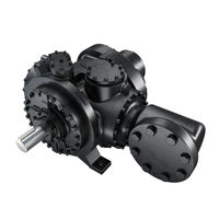
Emerson Vilter VSS204 Installation, Operation And Service Manual (84 pages)
HPLD Single Screw Bare Shaft Compressor
Brand:
Emerson
| Category:
Air Compressor
| Size: 18.65 MB
Table of Contents
Standard Vilter Warranty Statement
3
Important Message
5
EC Declaration of Incorporation
6
Table of Contents
7
Section 1 • General Information
13
How to Use this Manual
13
Additional Important Notes
13
System Unit Identification
14
Bare Shaft HPLD Compressor Model Designations
15
Section 2 • Theory of Operation
17
Introduction
17
Compressor
17
Table 2-1. HPLD Compressor Specifications
17
Capacity and Volume Control
18
Description of a Gas System for a Standard Compressor Set
19
Description of an Oil System for a Standard Compressor Set
19
Table 2-2. HPLD Compressor Volume Ratio Options
19
Critical Application Guidelines
20
Figure 2-1. Basic Single Screw Compressor System
20
Procedure for System Pressurization
21
Figure 2-2. Tubing Line to Pressurize the Unit (Bypassing the Compressor)
21
Alarm and Shutdown Readings
22
HPLD Package Requirements
23
Section 3 • Installation
25
Delivery Inspection
25
Rigging and Lifting of the Compressor
25
Table 3-1. Bare Shaft Compressor Weights
25
Figure 3-1. Rigging and Lifting Points (Top View)
25
Compressor Inspections Prior to Installation
26
Long Term Storage Recommendations
26
Long Term Storage Log
27
Notice on Using Non-Vilter Oils
28
Instrumentation Requirements
28
Pressure
28
Temperature
29
Miscellaneous
29
Figure 3-2. Additional Instruments
29
Piping
30
Testing System for Leaks
31
Hydrocarbon Systems
31
CO Systems
31
Oil for Single Screw Compressors
31
Section 4 • Operation
33
Notice on Using Non-Vilter Oils
33
Operation
33
Control System
33
Starting, Stopping and Restarting the Compressor
33
Safety Setpoints
33
HPLD Control with Vission20/20™ Micro-Controller
34
Section 5 • Maintenance/Service
35
Maintenance and Service Schedule
35
Recommendations When Servicing
36
Preparation of Unit for Servicing
36
Oil Sampling
37
Recommendations
37
Installation of the Oil Sampler Valve
37
Pre-Sampling
37
Figure 5-1. Oil Analysis Kit (VPN 3097A)
37
Sampling Procedure
38
Figure 5-2. Oil Sampler Valve (VPN #3708A) for Gas Compression Applications
38
Figure 5-3. Oil Sampling Valve (VPN #3709A) for Ammonia and Refrigerant Compressors
38
Figure 5-4. Operating the Oil Sampling Valve
39
Figure 5-5. Stages of the Oil Sample Taking Process
39
Oil Sample Analysis Report
40
Compressor Inspection
41
Bearing Inspection
41
A) Preparation
41
B) Main Rotor Bearing Inspection
41
Determining Maximum Applied Force for Main Rotor Bearings and Gaterotor Bearings
41
Figure 5-6. Bearing Radial Clearance Inspection
41
Method of Inspection
41
Table 5-2. Maximum Main Rotor Bearing Clearance
41
Figure 5-7. Bearing Axial Clearance Inspection
42
C) Gaterotor Bearing Inspection
43
Figure 5-8. Gaterotor Bearing Clearance
43
Table 5-3. Maximum Gaterotor Bearing Clearance
43
Gaterotor Inspection
44
A) Gaterotor - Main Housing Shelf Clearance
44
Figure 5-10. Gaterotor and Shelf Clearance Measurement Steps
44
Figure 5-9. Gaterotor and Shelf Clearance
44
B) Gaterotor Float Measurement
45
Figure 5-11. Visual Inspection between Gaterotor and Bushing
45
Figure 5-12. Gaterotor Float Dial Location
45
Table 5-4. Gaterotor Float
45
C) Gaterotor Backlash Inspection
46
Figure 5-13. Gaterotor Float
46
Figure 5-14. Alignment of Gaterotor
46
Figure 5-15. Location of Dial Indicator Magnetic Base
46
Figure 5-16. Placement of Dial Indicator
47
Figure 5-17. Measuring Backlash
47
Table 5-5. Backlash Range
47
Important Notes
48
Additional Inspections
48
Post Inspection
48
Figure 5-18. Chipped Edge of Gaterotor
48
Gaterotor Removal and Installation
49
Removal
49
Figure 5-19. Rotor Position for Gaterotor/Support Assembly Removal
49
Figure 5-20. Gaterotor/Support Assembly Removal
49
Figure 5-21. Gaterotor Assembly
50
Figure 5-22. Tool (A24061A) to Handle Suction Tee Assembly
51
Figure 5-23. Tool to Remove Bearing Housing Assembly
52
Figure 5-24. Tool to Install and Remove Bearing Housing Assembly
52
Installation
53
Gaterotor Blade Removal
55
Gaterotor Blade Installation
55
Gaterotor Ball Bearing Removal
56
Gaterotor Ball Bearing Installation
56
Gaterotor Roller Bearing Removal
57
Gaterotor Roller Bearing Installation
57
Compressor Shaft Seal Replacement
58
Shaft Seal Assembly
58
Handling Seal Face with Care
58
Shaft Seal Removal
59
Table 5-6. HPLD Shaft Seals
59
Prior to Shaft Seal Installation (for All HPLD Shaft Seal Models)
60
Shaft Seal Installation
61
Main Rotor Assembly
62
Torque Specifications
62
Using a Torque Wrench Correctly
63
Nord-Lock ® Washers
63
Section 6 • Troubleshooting
65
Section 7 • Warranty and Parts
69
Warranty Claim Processing
69
On-Site Service Support
71
Remanufactured HPLD Bare Shaft Single Screw Compressor
71
Explanation of Rebuild Levels
71
Section 8 • Spare Parts List
73
HPLD Recommended Spare Parts List
73
HPLD Compressor Kits
74
Compressor Gasket and O-Ring Kit
74
Gaterotor Kits
74
Shaft Seal Kit
74
Tool Kit
74
Suction Covers
75
Discharge Manifold
76
Housing
77
Appendix A Torque Specifications
79
Appendix B Vilter Oil
81
Advertisement
Advertisement
Related Products
Emerson Vilter VSS222
Emerson Vilter VSS243
Emerson VSSG
Emerson VSSG 291
Emerson VSSG 601
Emerson Vilter VSS128
Emerson Vilter VSS160
Emerson Vilter VSS180
Emerson Vilter VSS145
Emerson VSSG 451
Emerson Categories
Controller
Control Unit
Transmitter
Measuring Instruments
Fan
More Emerson Manuals
Login
Sign In
OR
Sign in with Facebook
Sign in with Google
Upload manual
Upload from disk
Upload from URL