
Related Manuals for Emerson VSG


Summary of Contents for Emerson VSG
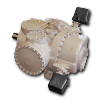
- Page 1 VSG & VSSG Single Screw Bare Shaft Compressor The World’s Best Compressors For Gas Compression...
-
Page 3: Important Message
P.O. Box 8904 5555 South Packard Ave Cudahy, WI 53110-8904 USA Telephone: 1-414-744-0111 Fax:1-414-744-3483 e-mail: info.vilter@emerson.com Equipment Identification Numbers: Vilter Order Number: _______________________Compressor Serial Number: _________________ Vilter Order Number: _______________________Compressor Serial Number: _________________ Vilter Order Number: _______________________Compressor Serial Number: _________________... -
Page 5: Table Of Contents
Table of Contents Important Message .................... 3 VSG STANDARD VILTER WARRANTY STATEMENT ..........6 Long Term Storage Requirements ............... 7 Critical Applications Guidelines ................8 Instrumentation Requirements ..............9 Alarm and Shutdown Readings ..............11 VSG Package Requirements ................12 Description .................... -
Page 6: Vsg Standard Vilter Warranty Statement
VSG STANDARD VILTER WARRANTY STATEMENT Seller warrants all new single screw gas compression units and bareshaft single screw compressors manufactured by it and supplied to Buyer to be free from defects in materials and workmanship for a period of (a) eighteen (18) months from the date of shipment or (b) twelve (12) months from the date of installation at the end user’s location, whichever occurs first. -
Page 7: Long Term Storage Requirements
Long Term Storage Requirements Note: At the time of purchase Vilter Manufacturing must be notified. The compressor(s) must be stored in a heated building, preferably air conditioned to control moisture, to prevent corrosion of the main rotor shaft and for the compressor. The slide valve (volume ratio&... -
Page 8: Critical Applications Guidelines
Gas composition plays a role in the performance of the VSG compressor as well. While the VSG is capable of handling a wide variety of gases, it is required that the concentration of H S in the pro- cess gas not exceed 100 PPM. -
Page 9: Instrumentation Requirements
Instrumentation Requirements Pressure Temperature There are four pressure transducers required to read There are four temperature readings required for system pressures as listed below. processor control, as listed below. 1. Suction pressure transducer (-15.0 - 300 PSIG) 5. Suction temperature RTD measures the tem- measures the gas suction pressure into the com- perature of the incoming suction gas, and is pressor housing, which provides the permissive... - Page 10 Instrumentation Requirements MOTOR COMPRESSOR OIL SEPARATOR STANDARD SINGLE OIL FILTER OPTIONAL DUAL OIL FILTERS OIL COOLER STANDARD WATER COOLED OIL COOLER OPTIONAL REMOTE AIR COOLED OIL COOLER Miscellaneous: Additional instrumentation devices required are a current transformer mounted around one phase of the drive motor leads to measure main motor amperage, and two rotary potentiometers to read the position of the slides.
-
Page 11: Alarm And Shutdown Readings
Alarm and Shutdown Readings addition to this alarm and shutdown, the compressor The control system for the VSG compressor must protect the package is ultimately protected from damage due to machine from damage caused by running outside of normal over pressurization by at least one discharge pressure operating conditions by providing operators with alarms relief valve located on the oil separator. -
Page 12: Vsg Package Requirements
Pressure (MAWP) of the separator. Note - Because the oil system on the VSG compressor utilizes discharge gas pressure as the means to move the injection oil through the system, it must be remembered that all components of the oil system are exposed to full discharge... -
Page 13: Description
As the main screw rotates, the gate rotor is also The VSG compressors are comprised of three driven, causing the gate rotor tooth to sweep the rotating assemblies: the main screw assembly groove in the main screw. - Page 14 The Vilter VSG compressors feature the port. When the slide is extended fully to the exclusive Parallex™ Slide System, which discharge end of the screw (the 100% posi-...
- Page 15 Description DESCRIPTION OF GAS SYSTEM FOR A STANDARD DESCRIPTION OF OIL SYSTEM FOR A STANDARD COMPRESSOR SET COMPRESSOR SET The gas passes through a stop valve and a check At start oil at is drawn from the oil separator tank by the valve and then through a mesh strainer mounted oil pump, and passes through a oil cooler and micronic directly to the inlet flange.
-
Page 16: Installation
Installation PIPING For halocarbon piping, only wrought copper fit- tings should be used. Cast fittings as used for water Before installing piping, the compressor inlet and service are porous and will allow the refrigerant to outlet ports should be inspected to ensure no dirt escape. - Page 17 Installation TESTING SYSTEM FOR LEAKS OIL FOR SINGLE SCREW COMPRESSORS Vilter equipment is tested for leaks at the factory. One the most important steps in putting the system Due to the need for adequate lubrication, Vilter rec- into operation is field testing for leaks. This must ommends only the use of Vilter lubricants, designed be done to assure a tight system that will operate specifically for Vilter compressors.
-
Page 18: Installation & Calibration Of Slide Valve Actuators
Installation & Calibration of Slide Valve Actuators Slide Valve Actuator Installation Instructions 3. If not already done, mount the slide valve actua- tor per (“Vilter Actuator set up for Capacity and Caution Volume Slide Motors). Next, wire the actuator per the attached wiring diagrams, using the WHEN INSTALLING THE OPTICAL SLIDE MOTOR, already installed electrical conduit to run the LOOSEN LOCKING COLLAR BEFORE SLIDING THE... - Page 19 Installation & Calibration of Slide Valve Actuators Caution: there are wires attached to the con- 15. Use the DEC button on the control panel to nector on the plastic cover. Handling the drive the slide valve to its minimum “mechani- cover too aggressively could break the wires.
- Page 20 Installation & Calibration of Slide Valve Actuators 21. Use the INC button to rotate the actuator to- wards its maximum position while watching the millivolt readout on the controller screen. Discontinue pressing the INC button when the millivolt reading in the “Current” window is approximately 9200 millivolts (7900 mil- livolts for the 2783J qualified analog boards).
-
Page 21: Slide Valve Operation
Slide Valve Operation Slide Valve Actuator Operation This scheme is not foolproof. If the motor is moved The slide valve actuator is a gear-motor with a posi- manually while the power is off or the motor brake tion sensor. The motor is powered in the forward has failed, allowing the motor to free wheel for too and reverse directions from the main computer in long after the position sensor looses power, the ac-... -
Page 22: Slide Valve Actuator Trouble Shooting Guide
Slide Valve Actuator Trouble Shooting Guide Problem Reason Solution Dirt or debris is blocking one or Clean the optocoupler slots The actuator cannot be cali- both optocoupler slots with a Q-Tip and rubbing alco- brated hol. The photochopper fence extends Adjust the photochopper so less than about half way into the that the fence extends further... - Page 23 Slide Valve Actuator Trouble Shooting Guide Problem Reason Solution The actuator does not trans- The motor was manually moved Recalibrate. mit the correct position after while the position sensor was not a power loss powered. Get the motor brake to where it The motor brake is not working operates freely and then recali- properly...
- Page 24 Slide Valve Actuator Trouble Shooting Guide Problem Reason Solution The motor runs sporadically Replace the actuator. Bad thermal switch See above. Any of the reasons listed in “The motor will not move in either direc- tion” The motor runs but output Replace the actuator.
- Page 25 Slide Valve Actuator Trouble Shooting Guide *__________________ This indicates a skipped state in the patterns generated by the optocouplers as the motor moves. This error means that the slide valve actuator is no longer transmit- ting accurate position information. The actuator should be recalibrated as soon as possible.
-
Page 26: Operation Section
Operation Section Notice on using Non -Vilter Oils Oil and its additives are crucial in system performance. Vilter Manufacturing will NOT APPROVE non-Vilter oils for use with Vilter compressors. Due to the innumerable choices available it is not possible for us to test all oils offered in the market place, and their effects on our equipment. - Page 27 Ratio 2. Slide Valve Control Actuators Capacity and volume ratio control of the screw com- pressor is achieved by movement of the respective slide valves, actuated by electric motors. SLIDE VALVE ACTUATOR LOCATION: VSG 501 CW Thru VSG 701 CW...
- Page 28 1.09 / / 4.283” 0.63 / / 2.473” VSG 901 1.09 / / 4.283” 0.63 / / 2.473” VSG 1051 CCW 1.22 / / 4.777” 0.74 / / 2.889” VSG 1201 CCW 1.22 / / 4.777” 0.74 / / 2.889”...
-
Page 29: Maintenance
Maintenance Gas Compression Maintenance and Inspection Schedule 120,000 110,000 100,000 90,000 80,000 70,000 60,000 50,000 40,000 30,000 20,000 10,000 5,000... -
Page 30: Service
Service GENERAL COMMENTS When working on the compressor, care must be taken to ensure that contaminants (i.e. water from melting ice, dirt and dust) do not enter the compressor while it is being serviced. It is essential that all dust, oil or ice that has accumulated on the outside of the com- pressor be removed before servicing the compressor. - Page 31 Service Top View Rotor Being Pushed By COMPRESSOR INSPECTION Use Of Lever Direction of rotor movement. Axial force at coupling The Vilter Single Screw Compressor is designed for to be 300-500lbs. long periods of trouble free operation with a mini- mum of maintenance.
- Page 32 VSG 501 THRU 701 0.045” C) Gate rotor bearing float. VSSG 291 THRU VSSG 601 0.045” VSG 751 & VSG 901 0.055” 1) Remove the side covers and position a dial VSG 1051 & VSG 1201 0.060” indicator on the gate rotor.
- Page 33 D) Insert the gate rotor stabilizer. The side rails are not required on VSSG 291 thru 601. For the VSG 751 thru 901 and VSG 1051 thru 1201 compressors, use the side rails and assemble to the gate rotor stabilizer as stamped. For the VSG 1551 thru 2101, use the side rails and assemble to the gate rotor stabilizer.
- Page 34 Service E) Remove the hex head and socket head bolts from the thrust bearing cover. Insert two of the bolts into the threaded jacking holes to assist in remov- ing the cover. Retain the shim pack and keep it with the bearing housing cover. F) Hold the gate rotor support with a suitable wrench on the flats provided near the roller bearing hous- ing.
- Page 35 Service REMOVAL (ALL VSG 301-701 MODELS) The removal of the gate rotor assembly for the VSG 301-701 compressors is similar for the VSG 901- 2101 compressors. The inner races are secured to the stationary bearing spindle. A) Prepare the compressor for servicing.
- Page 36 Service E) Remove plug on the thrust bearing housing. Loosen the socket head cap screw that is located underneath the plug. This secures the inner races of the thrust bearings to the spindle. F) Remove bolts that hold the thrust bearing hous- ing to the compressor.
- Page 37 Service INSTALLATION (All VSG Models) A) Install the gate rotor support by carefully tilting the roller bearing end of the gate rotor support towards the suction end of the compressor. The compressor input shaft may have to be rotated to facilitate the installation of the gate rotor sup- port.
- Page 38 Service D) Set the clearance between the gate rotor blade and the shelf. Place a piece of 0.003”-0.004” shim stock between the gate rotor blade and the shelf. Measure the depth from the top of the com- pressor case to the top of the thrust bearing housing.
- Page 39 Service INSTALLATION (All VSG 301-701 Models) A) Install the gate rotor support. Carefully tilt the roller bearing end of the gate rotor support to- wards the suction end of the compressor. The compressor input shaft may have to be rotated to facilitate the installation of the gate rotor support.
- Page 40 Service GATE ROTOR BLADE REMOVAL A) Remove the gate rotor assembly. B) Remove the snap ring and washer from the gate rotor assembly. Lift gate rotor blade assembly off the gate rotor support. C) Check damper pin and bushing for excessive wear. Replace if necessary.
- Page 41 A) Refer to section INSTALLATION (All VSG Models) for removal of the gate rotor bearing housings and gate rotor supports. B) For removal of thrust bearings on VSG units: 1) Remove bolts (150) from the clamping ring (114). 2) Remove thrust bearing clamping ring.
- Page 42 Service GATE ROTOR THRUST BEARING INSTALLA- TION A) For installation of thrust bearings on VSG and VSSG units: 1) Install bearings (126) in the housing so the bearings are face to face. The larger sides of the inner races are placed together.
- Page 43 Service GATE ROTOR ROLLER BEARING REMOVAL A) Refer to section REMOVAL ( All VSG) for removal of the gate rotor bearing housings and gate rotor supports. B) Remove the snap ring (131), which retains the roller bearing in the bearing housing.
- Page 44 Current Shaft Seal and for all Replacement. COMPRESSOR SHAFT SEAL REMOVAL A) Prepare the compressor for servicing as outlined in section REMOVAL ( All VSG) . B) Remove bolts (281) holding the shaft seal cover (218). Insert two of the bolts into the threaded jacking holes to assist in removing the cover.
- Page 45 Service COMPRESSOR SEAL INSTALLATION NOTE: When replacing the stationary members of the seal on the VSSG 291 thru VSSG 601 the roll pin in the cover is used only with the seal assembly having a station- ary mirror face. If a seal assembly with a stationary carbon face is installed, the roll pin must be removed.
- Page 46 Service MAIN ROTOR ASSEMBLY shoulder on the input shaft. Make sure the seal is seated against the shoulder. If the seal is not fully seated against the shoulder, the shaft seal Due to the procedures and tools in- carbon will be damaged when the seal cover is volved in the disassembly and reas- installed.
- Page 47 Service INSPECTION OF SLIDE VALVE ASSEMBLIES IN THE COMPRESSOR Prepare the compressor for servicing. A) Remove the gate rotor access covers. Using a mirror and flashlight, visually inspect the slide valve carriage through the gas bypass opening. Look for any significant signs of wear on the slide valve carriage.
- Page 48 Service D) Locate and remove the socket head plugs above the slide valve carriage attachment bolts. Re- move the bolts located under the plugs. E) The slide valve carriage may now be removed. On newer carriages there is a threaded hole in the back of the slide valve carriage to aid in its removal.
- Page 49 Service COMMAND SHAFT ASSEMBLY REMOVAL The following steps can be used to remove or install either the capacity or volume command shaft as- semblies. A) Prepare the compressor for servicing. B) Follow the appropriate instructions to remove control actuator. C) Remove four socket head cap screws (457) and Nord-Lock washers (477) securing mounting plate (415) to manifold.
- Page 50 O-ring seal to vent to atmosphere NOTE: and not into the slide valve motor housing. When removing the discharge manifold on VSG 301-701 Install snap ring retainer and washer on the compressor the compressor must be properly supported command shaft.
- Page 51 Install the dowel pins and bolts, tighten manifold bolts to the recom- mended torque value. B) On VSG 751-2101 and VSSG 291-601 compres- sors install the discharge spool or elbow be- tween the discharge manifold and oil separator with new gaskets.
- Page 52 Install clamps, spacers and bolts on both sides. Tighten the bolts to the recom- mended torque values. B) The slide valve sets must be synchronized on VSG 751-2101 and dual gate VSG 301-701 units. Both slide valve racks for either the volume ratio or...
- Page 53 Service TORQUE SPECIFICATIONS (ALL UNITS IN FT.-LBS) HEAD OUTSIDE DIAMETER OF BOLT SHANK TYPE BOLT MARKINGS ” ” ” ” ” ” ” ” SAE GRADE 2 SAE GRADE 5 SAE GRADE 8 SOCKET HEAD CAP SCREW TORQUE SPECIFICATION FOR 17-4 STAINLESS STEEL FASTENERS (FT-LBS) TYPE ¼”...
- Page 54 Service USING A TORQUE WRENCH CORRECTLY TORQUE WRENCHES USING A TORQUE WRENCH CORRECTLY INVOLVES FOUR PRIMARY CONCERNS: A. A smooth even pull to the break point is required. Jerking the wrench can cause the pivot point to break early leaving the bolt at a torque value lower then required. Not stopping when the break point is reached results in an over torque condition.
- Page 55 A. The Nord-Lock lock washer sets are used in many ® areas in both the VSG & VSSG screw compressors that require a vibration proof lock washer. B. The lock washer set is assembled so the course serrations that resemble ramps are mated together.
-
Page 57: Parts Section
Parts Section Recommended Spare Parts List Refer to the Custom Manual Spare Parts Section for Specific Applications Please have your Model # and Sales Order # available when ordering. These are found on the compressor’s Name Plate. -
Page 58: Gate Rotor
Gate Rotor... -
Page 59: Gate Rotor
Gate Rotor MODEL NUMBER ITEM DESCRIPTION VSSG 451 VSSG 601 QTY VPN QTY VPN GATE ROTOR BLADE AND BEARING REPLACEMENT KIT, 111, 118, 120A, 120B, 121, 122, 123, 124, 125, 126, KT712A KT712B 130, 131, 141, 142 & 143 GATE ROTOR BLADE REPLACE KIT, 111, 118, 120A, 120B, 121, 122, KT713A KT713B... - Page 60 Gate Rotor ITEM DESCRIPTION VSG 751 VSG 901 VSG 1051 VSG 1201 GATE ROTOR BLADE AND BEARING REPLACEMENT KIT, 111, 118, 120A, 120B, 121, 122, 123, 124, 125, 126, 130,131, 141, 142 & 143. KT712C KT712D KT712E KT712F GATE ROTOR BLADE REPLACE KIT, 111, 118, 120A, 120B, 121, 122, 123, 124, 130, 141, 142 &...
- Page 61 Gate Rotor ITEM DESCRIPTION VSG 1551 VSG1851 VSG 2101 GATE ROTOR BLADE AND BEARING REPLACEMENT KIT, 111, 118, 120A, 120B, 121, 122, 123, 124, 125, 126, 130, 131, 141, 142 & 143. KT712M KT712L KT712K GATE ROTOR BLADE REPLACEMENT KIT, 111, 118, 120A, 120B, 121, 122, 123, 124, 130, 141, 142 &...
-
Page 62: Shaft Seal
Shaft Seal Shaft Seal With Stationary Carbon Face MODEL NUMBER ITEM DESCRIPTION VSSG 291-601 VSG 751-1201 VSG 1551 thru 2101 KT709AG KT709BG KT709CG SHAFT SEAL VITON KIT, 219, 260, 230 OIL SEAL. 25040A 25064A 2930B O-RING. 2176F 2176AC 2176BH... -
Page 63: Tandem Shaft Seal
Tandem Shaft Seal SHAFT DIAMETER DESCRIPTION 2.25” 2.5” 2.875” TANDEM SHAFT SEAL 25713A 25713A 25713A 25713B 25713B 25713B... -
Page 64: Main Rotor
Main Rotor... -
Page 66: Slide Valve Cross Shafts And End Plate
Slide Valve Cross Shafts and End Plate... -
Page 67: Slide Valve Cross Shafts And End Plate
EXPANSION PIN. 2981AA SOCKET HEAD CAP SCREW. 2795F SET SCREW 2060J SET SCREW 2060H MODEL NUMBER ITEM DESCRIPTION VSG 751 & VSG 901 VSG 1051 & VSG 1201 END PLATE 25543A 25593A SHAFT. 25844A 25845A GEAR. 25027A 25027A RACK CLAMP. -
Page 68: Slide Valve Carriage Assembly
Slide Valve Carriage Assembly... - Page 69 Slide Valve Carriage Assembly MODEL NUMBER- ITEM DESCRIPTION VSSG 291 Thru VSSG 601 CARRIAGE ASSEMBLY. A25179B CAPACITY PISTON A25183B 340, 341, 350 & 355 VOLUME PISTON A25184B 340, 342, 350 & 355 GASKET SET 345B. A25200B RACK. 25024A RACK. 25023A 343A COVER, SEPARATE VOL.
- Page 70 Slide Valve Carriage Assembly MODEL NUMBER ITEM DESCRIPTION VSG 751 VSG 901 VSG 1051 VSG 1201 CARRIAGE ASSEMBLY. A25179C A25179C A25179D A25179D CAPACITY PISTON A25183C A25183C A25183D A25183D 340, 341, 350 & 355 VOLUME PISTON A25184C A25184C A25184D A25184D 340, 342, 350 & 355.
- Page 71 Slide Valve Carriage Assembly MODEL NUMBER ITEM DESCRIPTION VSG 1551 to 2101 CARRIAGE ASSEMBLY. A25179E CAPACITY PISTON A25183E 340, 341, 350 & 355 VOLUME PISTON A25184E 340, 342, 350 & 355 GASKET SET 345 & 378. A25200E RACK. 25779A RACK.
-
Page 72: Actuator & Command Shaft
Actuator & Command Shaft... - Page 73 Actuator & Command Shaft MODEL NUMBER VSSG 291 thru VSG 751 thru VSG 1051 thru VSG 1551 thru ITEM DESCRIPTION VSSG 601 VSSG 901 VSG 1201 VSG 2101 COMMAND SHAFT ASSEMBLY A25994B A25994C A25994D A25994E SLIDEVALVE ACUATOR 25972D 25972D 25972D...
-
Page 74: Miscellaneous Frame Components
Miscellaneous Frame Components VSG Screw Compressor... - Page 75 Miscellaneous Frame Components MODEL NUMBER ITEM DESCRIPTION VSSG 291 thru VSSG 601 GASKET AND O-RING KIT; KT710A1 FLANGE SET 513, 514 & 547A. A25190A ECON-O-MIZER PORT. A25190B MANIFOLD GASKET. 25503A FLANGE OIL. 25058A AFLANGE ECON-O-MIZER. 25058A FLANGE GASKET OIL. 11323D 514A FLANGE GASKET ECON-O-MIZER.
- Page 76 Miscellaneous Frame Components MODEL NUMBER ITEM DESCRIPTION VSG 751 VSG 901 VSG 1051 VSG 1201 GASKET AND O-RING KIT; KT710B KT710B KT710C KT710C FLANGE SET 513, 514 & 547. A25190A A25190A A25190B A25190B MANIFOLD GASKET. 25541A 25541A 25324A 25324A FLANGE OIL.
- Page 77 Miscellaneous Frame Components MODEL NUMBER ITEM DESCRIPTION VSG 1551 THRU VSG 2101 GASKET AND O-RING KIT; KT710D FLANGE SET 513, 514 & 547. A25190C FLANGE SET 513A, 514A & 547 ECON-O-MIZER PORT. A25190D MANIFOLD GASKET. 25676A FLANGE OIL. 12477C 513A FLANGE ECON-O-MIZER.
-
Page 78: Replacement Tools
Replacement Tools... - Page 79 912, 913, 914, 915, 916 & 917). A25205B GATEROTOR STABILIZER SET (901A, 901B & 901C). A25698A MODEL NUMBER ITEM DESCRIPTION VSG 751 VSG 901 VSG 1051 VSG 1201 GATEROTOR TOOLS (901, 910, 911, 912, 913, 914, 915, 916 & 917). A25205C A25205C...
- Page 80 Replacement Tools MODEL NUMBER ITEM DESCRIPTION VSG 1551 thru VSG 2101 GATEROTOR TOOLS (901, 910, 911, 912, 913, 914, 915, 916 & 917). A25205E GATEROTOR STABILIZER SET (901A, 901B, 901C & 901D). A25699A...
-
Page 81: Vsg 301-701 Replacement Parts Section
VSG 301-701 Replacement Parts Section Recommended Spare Parts List Refer to the Custom Manual Spare Parts Section for Specific Applications Please have your Model # and Sales Order # available when ordering. These are found on the compressor’s Name Plate. -
Page 82: Gaterotor Assembly
Gaterotor Assembly... -
Page 83: Gaterotor Assembly
Part totals indicated are for one gate rotor assembly, machines with two gate rotors will require double the components listed below. MODEL NUMBER ITEM DESCRIPTION VSG 301 VSG 361 VSG 401 SUPPORT ASSEMBLY 110 & 135B. A25222AB 1 A25222AA 1 A25222AC GATE ROTOR &... - Page 84 Gaterotor Assembly Part totals indicated are for one gate rotor assembly, dual gate machines will require double the components. MODEL NUMBER ITEM DESCRIPTION VSG 501 VSG 601 VSG 701 SUPPORT ASSEMBLY 110 & 135B. A26011BB 1 A26011BA 1 A26011BA GATE ROTOR & DAMPER ASSEMBLY 111,120.
-
Page 85: Shaft Seal
Shaft Seal MODEL NUMBER ITEM DESCRIPTION ALL VSG 301-401 ALL VSG 501-701 SHAFT SEAL KIT Viton Kit KT709DG KT709AG 219, 230, & 260. SHAFT SEAL. OIL SEAL. 2930C 25040A 244- TEFLON SEAL 25939A 25939A 252- RETAINER RING 2928M 2928M O-RING... -
Page 86: Main Rotor, Slide Valve Cross Shafts & End Plate
Main Rotor, Slide Valve Cross Shafts & End Plate Models VSG301-401 Counter Clockwise ONLY... - Page 87 Main Rotor, Slide Valve Cross Shafts & End Plate Models VSG301-401 Counter Clockwise ONLY MODEL NUMBER ITEM DESCRIPTION VSG 301 VSG 361 VSG 401 MAIN ROTOR ASSEMBLY. A25226AB 1 A25226AA 1 A25226AC OIL BAFFLE ASSEMBLY (1) 217, (1) 244, (1) 248, (1) 249, (1) 252. 1...
- Page 88 Main Rotor, Slide Valve Cross Shafts & End Plate Models VSG501-701 Clockwise ONLY...
- Page 89 Main Rotor, Slide Valve Cross Shafts & End Plate Models VSG501-701 Clockwise ONLY MODEL NUMBER ITEM DESCRIPTION VSG 501 VSG 601 VSG 701 MAIN ROTOR ASSEMBLY. A26010BB 1 A26010BA 1 A26010BC OIL BAFFLE ASSEMBLY (1) 217, (1) 244, (1) 248, (1) 249, (1) 252.
-
Page 90: Slide Valve Carriage Assembly
Slide Valve Carriage Assembly... - Page 91 Slide Valve Carriage Assembly MODEL NUMBER ITEM DESCRIPTION ALL VSG 301-401 ALL VSG 501-701 CARRIAGE ASSEMBLY. A25179A A26012B CAPACITY PISTON A25183A A25183B 340, 341, 350 & 355. VOLUME PISTON A25184A A25184B 340, 342, 350 & 355 CAPACITY RACK. 25023D 25024A CAPACITY RACK SHAFT.
-
Page 92: Actuator & Command Shaft
Actuator & Command Shaft... - Page 93 Actuator & Command Shaft MODEL NUMBER VSSG 291 thru VSG 751 thru VSG 1051 thru VSG 1551 thru ITEM DESCRIPTION VSSG 601 VSSG 901 VSG 1201 VSG 2101 COMMAND SHAFT ASSEMBLY A25994B A25994C A25994D A25994E SLIDEVALVE ACUATOR 25972D 25972D 25972D...
-
Page 94: Miscellaneous Frame Components
Miscellaneous Frame Components Model VSG 301-401 Model VSG 501-701... - Page 95 Miscellaneous Frame Components MODEL NUMBER ITEM DESCRIPTION ALL VSG 301-401 ALL VSG 501 - 701 MANIFOLD GASKET. 25737A 26037A ECON-O-MIZER GASKET. 11323GG 11323D COUPLING LOCK PLATE 25004D LOCK WASHER 3004H ECON-O-MIZER PLUG. 25419A 25397K O-RING 2176BF DOWEL PIN 2868B 2868B...
- Page 96 Miscellaneous Frame Components...
- Page 97 Miscellaneous Frame Components Housing Accessories MODEL NUMBER ITEM DESCRIPTION VSG 301 - 701 GATE ROTOR COVER. 25416B COVER GASKET. 25259B GASKET. 11323T INLET SCREEN. 25920A PISTON COVER. * 25724B MODEL NUMBER ITEM DESCRIPTION VSG 301 - 401 VSG 501 - 701 O-RING.
-
Page 98: Replacement Tools
Replacement Tools MODEL NUMBER ITEM DESCRIPTION ALL VSG 301-401 ALL VSG 501-701 GATEROTOR STABILIZER. 25742A 25742B SEAL INSTALLATION TOOL 25455A 25455B... - Page 100 P.O. Box 8904 Cudahy, WI. 53110-8904 P: 414-744-0111 F: 414-744-1769 www.vilter.com (1/2011) Emerson and Vilter are trademarks of Emerson Electric Co. or one of its affiliated companies. ©2011 Emerson Climate Technoligies, Inc. All rights reserved. Printed in the USA. 35391SB Rev. 06...
Need help?
Do you have a question about the VSG and is the answer not in the manual?
Questions and answers