
Related Manuals for oventrop Aktor M ST L


Summary of Contents for oventrop Aktor M ST L
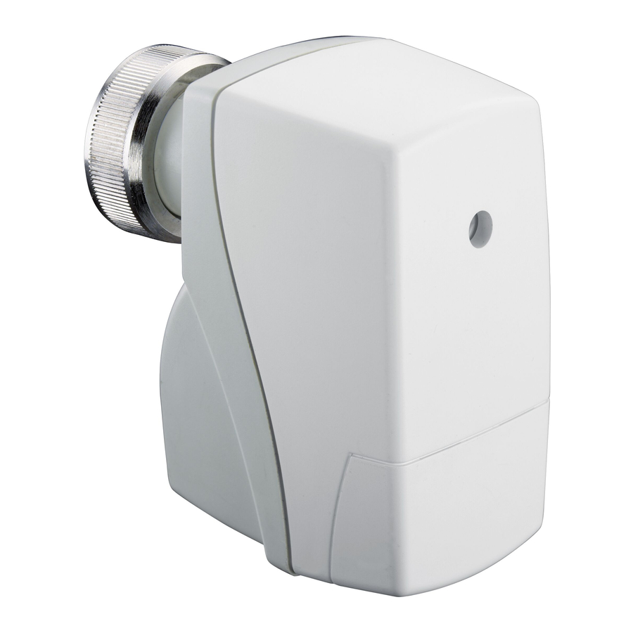
- Page 1 Valves, controls + systems Electromotive actuator "Aktor M ST L ", 24 V, 0 - 10 V Operating instructions...
-
Page 3: Table Of Contents
“Aktor M ST L 24V” Contents Contents Page General information ........................5 Validity of the operating instructions ..................5 Type plate ..........................5 Extent of supply ........................5 Contact ............................5 EU Declaration of conformity ....................5 Used symbols ..........................5 Safety-related information ......................6 Correct use ..........................6 Warnings ...........................6... - Page 4 Contents “Aktor M ST L 24V” 101271784-V02.01.2020...
-
Page 5: General Information
The operating instructions in other languages were translated from German. Validity of the operating instructions These operating instructions are valid for the elec- tromotive actuator "Aktor M ST L", 24 V, modulating proportional actuator, 0-10 V, with electric emergency control function and automatic recognition of neutral point. Type plate The type plate is located on the bottom of the prod- uct. -
Page 6: Safety-Related Information
Safety-related information “Aktor M ST L 24V” Safety-related information NOTICE Indicates a situation which may lead to dam- Correct use age to property if not avoided. Safety in operation is only guaranteed if the product is used correctly. Safety notes The Aktor may be used as actuator with electric We have developed this product in accordance with emergency control function and automatic recogni- current safety requirements. -
Page 7: Technical Description
“Aktor M ST L 24V” Technical description Technical description will move to the emergency end position (see section 6.3 on page 10). Construction Technical data 86.5 Operating voltage 24 V AC ±10 %; 50/60 Hz; 24 V DC ±10 % Power consump- Dimensioning: 6.8 VA (24 V tion AC); 3.3 W (24 V DC) nominal: 5.3 VA (24 V AC); 2.7 W (24 V DC) Start up load For short periods max. 12 A Drive Steady control 0 - 10 V DC;... -
Page 8: Transport And Storage
Transport and storage “Aktor M ST L 24V” Transport and storage Installation Temperature Initial installation 0 °C - 50 °C range Make sure that there is enough space for the Relative air hu- 0 - 85% r.h., not condensing installation of the actuator when installing the midity valve. -
Page 9: Configuration Of The Dip Switches
“Aktor M ST L 24V” Installation Configuration of the DIP switches f Remove the casing cover. f Configure the DIP switches according to the valve 1 2 3 4 5 used (see section 10 on page 12). U = 0 - 10 V DC 0 V DC Y = 0 - 10 V DC... -
Page 10: Operation
Operation “Aktor M ST L 24V” Operation Maintenance The actuator is maintenance-free. Status LED Removal and reinstallation Removal Illust. 6: Status LED Status LED The status LED is located under the casing cover and displays the operating status of the actuator. -
Page 11: Disposal
“Aktor M ST L 24V” Disposal Disposal Guideline 2012/19/EU WEEE: Waste electrical and electronic equipment (WEEE) must not be disposed of with do- mestic waste, but must be dropped off at a collection point for the recycling of electri- cal and electronic appliances. NOTICE Risk of environmental pollution Incorrect disposal (for instance with the domestic waste) may lead to environmental damage. f Packaging material is to be disposed of in an environmentally friendly manner. -
Page 12: 10. Appendix
Appendix “Aktor M ST L 24V” 10. Appendix Settings of the DIP switches Valve + actuator = Model Control range DIP switches DIP switches Valve type DN 10/15 30 - 90 l/h OFF ON OFF OFF 91 - 150 l/h OFF ON... - Page 14 OVENTROP GmbH & Co. KG Paul-Oventrop-Straße 1 59939 Olsberg GERMANY 101271784 V02.01.2020 www.oventrop.com...
Need help?
Do you have a question about the Aktor M ST L and is the answer not in the manual?
Questions and answers