
Related Manuals for oventrop Regtronic RM


Summary of Contents for oventrop Regtronic RM
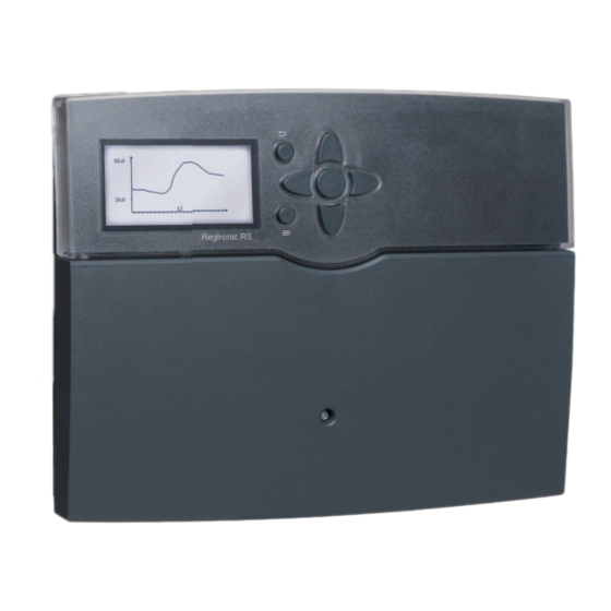
- Page 1 Valves, controls + systems ”Regtronic RM“ ”Regtronic RS“ (”Regucor“) Installation and operating instructions for the specialised installer...
- Page 2 Safety advice Target group Note Notes are indicated with an information Please pay attention to the following safety advice These instructions are exclusively addressed to au- symbol. in order to avoid danger and damage to people and thorised skilled personnel. property.
-
Page 3: Table Of Contents
“Regtronic RM” “Regtronic RS” (“Regucor”) Contents Solar ............35 Overview ............ 4 1.1 Optional functions ...........5 8.1 Basic solar settings ..........35 Installation ..........5 8.2 Solar optional functions ........38 2.1 Mounting ..............5 8.3 Solar expert menu ..........52 2.2 Electrical connection ..........6 Arrangement ........... -
Page 4: Overview
Mode of operation: type 1.Y • Drainback option Rated impulse voltage: 2.5 kV • Time-controlled thermostat function Interfaces: OVENTROP S-Bus, SD card slot • Thermal disinfection Functions: System controller for solar and heating • OVENTROP S-Bus systems. Functions such as: ∆T control, pump speed •... -
Page 5: Optional Functions
Installation Optional functions Mounting The unit must only be located in dry interior rooms. Solar The controller must additionally be supplied from a Bypass double pole switch with contact gap of at least 3 mm. Please pay attention to separate routing of sensor ca- CS-Bypass bles and mains cables. -
Page 6: Electrical Connection
Electrical connection Note WARNING! Electric shock! Connecting the device to the power supply Upon opening the housing, live must always be the last step of the instal- parts are exposed! lation! Î Always disconnect the con- The controller is equipped with 14 relays in total to troller from power supply which loads such as pumps, valves, etc. -
Page 7: Data Communication / Bus
RS: FW7 IP 20 in RM: S15 / V40 The controller is equipped with the Oventrop S-Bus The terminals S13 to S15 can be used as impulse in- for data transfer with and energy supply to external puts for V40 flowmeters or as inputs for FS08 flow GDSD2 modules. -
Page 8: Sd Card Slot
If fl owmeters, Grundfos Direct Sensors™ and / or ex- Sensors can be allocated to more than one function. The “Regtronic RM” / “Regtronic RS” (“Regucor”) is ternal extension modules are connected, these have a controller that offers a broad variety of functions For further information about heating circuits and op- to be registered in the In- / Outputs menu. -
Page 9: Operation And Function
Operation and function Selecting menu points and adjusting Buttons values The controller is operated via the 7 buttons next to the display. They have the following functions: During normal operation of the controller, the display is in the main menu. If no button is pressed for a few Button - scrolling upwards seconds, the display illumination goes out. - Page 10 adjusted value (not yet confi rmed) adjustment channel If more than one item of several can be selected, they active area inactive area will be indicated with checkboxes. When an item has been selected, an x appears inside the checkbox. When two values are locked against each other, they will display a reduced adjustment range depending on minimum value...
- Page 11 Adjusting the timer When the Timer option is activated, a timer is in- Adding a time frame: dicated in which time frames for the function can be The time frames can be adjusted in steps of 15 minutes. adjusted. In order to add an active time frame, proceed as fol- First of all, an overview of the current adjustments is lows: displayed.
- Page 12 Removing a time frame: In order to remove an active time frame, proceed as follows: Î Determine the point from which on the time frame is to be removed by pressing button Î Move the cursor to the desired ending point of the time frame by pressing buttons Î...
-
Page 13: Menu Structure
Menu structure The menu items and adjustment values se- Main menu lectable are variable depending on adjustments Status already made. The figure only shows an exem- Solar Solar plary excerpt of the complete menu in order to Arrangement visualise the menu structure. Basic setting Basic setting Heating... -
Page 14: Initial Commissioning
Initial commissioning When the hydraulic system is fi lled and ready for op- 1. Language: eration, connect the controller to the mains. Î Adjust the desired menu language. The controller runs an initialisation phase in which the directional pad fl ashes red. When the controller is commissioned for the fi rst time or when it is reset, it will run a commissioning menu after the initialisation phase. - Page 15 3. Daylight savings time adjustment: Î Activate or deactivate the automatical daylight savings time adjustment. 4. Time: 7. Completing the commissioning menu: Î Adjust the clock time. First of all adjust the hours, After the system has been selected, a security enquiry then the minutes.
-
Page 16: Basic Systems And Hydraulic Variants
Basic systems and hydraulic variants Variant System The selection of the basic solar system is one of the most important adjustments and is thus requested al- ready in the commissioning menu. First, the basic system is adjusted by means of the number of stores and collectors fi elds, then the hy- draulic variant. -
Page 17: Overview Of Relay And Sensor Allocation
Overview of relay and sensor allocation System 1 („Regtronic RS“ only) Second heating circuit Note optional In the “Regtronic RS” (“Regucor”) controller, the relay and sensor allocations described here are pre-adjusted. For the system adjustments of the “Regtronic RM” controller see page 19. Regucor (PWM 1) Relay / sensor allocation... - Page 18 System 2 variant 2 („Regtronic RS“ only) Second heating circuit Note optional In the “Regtronic RS” (“Regucor”) controller, the relay and sensor allocations described here are pre-adjusted. For the system adjustments of the “Regtronic RM” controller see page 19. Regucor Note If this system variant is selected, the pre- adjusted connections of the solar pump and...
- Page 19 System 1 (suitable for “Regtronic RM” and “Regtronic RS”) Relay / sensor allocation 10-14 Optional Optional Optional Optional Optional Optional Optional Optional Optional Relay Solar pump function function function function function function function function function Sensor Collector 1 Store base...
- Page 20 System 2 variant 2 (suitable for “Regtronic RM” and “Regtronic RS”) Relay / sensor allocation 10-14 Optional Optional Optional Optional Optional Optional Optional Relay 2PV coll. 1 2PV coll. 2 Solar pump function function function function function function function Sensor...
- Page 21 System 3 variant 2 (“Regtronic RM” only) Relay / sensor allocation 10-14 Solar pump Solar pump Optional Optional Optional Optional Optional Optional Optional Optional Relay Store 1 Store 2 function function function function function function function function Sensor Collector Store 1 base...
- Page 22 System 4 variant 1 S1 S6 (“Regtronic RM” only) Relay / sensor allocation 10-14 Optional Optional Optional Optional Optional Optional Optional Pump coll. 1 Pump coll. 2 Relay Store 2 function function function function function function function Collector 1 Store 1 base...
- Page 23 System 4 variant 3 S1 S6 (“Regtronic RM” only) Relay / sensor allocation 10-14 Solar pump Solar pump Optional Optional Optional Optional Optional Optional 2PV coll. 1 2PV coll. 2 Relay store 1 store 2 function function function function function...
- Page 24 System 5 variant 1 (“Regtronic RM” only) Relay / sensor allocation 10-14 Optional Optional Optional Optional Optional Optional Solar pump Relay Store 1 Store 2 Store 3 function function function function function function Collector 1 Store 1 base Free Store 2 base...
- Page 25 System 5 variant 3 (“Regtronic RM” only) Relay / sensor allocation 10-14 Optional Optional Optional Optional Optional Optional Optional Solar pump Relay Store 1 Store 2 function function function function function function function Collector 1 Store 1 base Free Store 2 base...
- Page 26 System 6 variant 2 (“Regtronic RM” only) Relay / sensor allocation 10-14 Solar pump Solar pump Solar pump Optional Optional Optional Optional Optional 2PV coll. 1 2PV coll. 2 Relay store 1 store 2 store 3 function function function function...
- Page 27 System 6 variant 4 S1 S6 (“Regtronic RM” only) Relay / sensor allocation 10-14 Optional Optional Optional Optional Optional Optional Pump coll. 1 Pump coll. 2 3PV store 1 3PV store 2 Relay function function function function function function Collector 1...
- Page 28 System 7 variant 1 (“Regtronic RM” only) Relay / sensor allocation 10-14 Optional Optional Optional Optional Optional Solar pump Relay Store 1 Store 2 Store 3 Store 4 function function function function function Collector 1 Store 1 base Free Store 2 base...
- Page 29 System 7 variant 3 (“Regtronic RM” only) Relay / sensor allocation 10-14 Solar pump Solar pump Solar pump Solar pump Optional Optional Optional Optional Optional Optional Relay store 1 store 2 store 3 store 4 function function function function function...
- Page 30 System 8 variant 2 (“Regtronic RM” only) Relay / sensor allocation 10-14 Optional Optional Optional Optional Optional Pump coll. 1 Pump coll. 2 Relay Store 1 Store 2 Store 3 function function function function function Collector 1 Store 1 base...
- Page 31 System 8 variant 4 (“Regtronic RM” only) Relay / sensor allocation 10-14 Optional Optional Optional 2PV coll. 1 2PV coll. 2 Solar pump Relay Store 1 Store 2 Store 3 Store 4 function function function Collector 1 Store 1 base...
- Page 32 System 9 variant 1 (“Regtronic RM” only) Relay / sensor allocation 10-14 Optional Optional Optional Optional Solar pump Relay Store 1 Store 2 Store 3 Store 4 Store 5 function function function function Collector 1 Store 1 base Free Store 2 base...
- Page 33 System 9 variant 3 (“Regtronic RM” only) Relay / sensor allocation 10-14 Solar pump Solar pump Solar pump Solar pump Solar pump Optional Optional Optional Optional Optional Relay store 1 store 2 store 3 store 4 store 5 function function...
-
Page 34: Main Menu
Main menu Status If, for example, Solar / System is selected, a submenu with the sensors and relays allocated to the solar sys- tem opens. In the submenu, the current temperatures and the current pump speed are displayed. When a line with a measurement value is selected, another submenu will open. -
Page 35: Solar
Solar Solar Messages In the Status / Messages menu, error and warning mes- In the Status / Solar menu, the status of the solar In this menu, all adjustments for the solar part of the sages which have not been acknowledged are indicated. system, the solar loading and the selected optional arrangement can be made. - Page 36 Collector (1/2) In systems with 2 collector fi elds, 2 seperate menu items (Collector 1 and Collector 2) are displayed instead of Collector. For each collector fi eld, a collector minimum limita- tion and a collector emergency shutdown tempera- ture can be adjusted. First of all, the basic solar system can be selected ac- cording to the number of stores and collector fi elds in use.
- Page 37 Solar / Basic settings / Store (1 / 2 / 3 / 4 / 5) The store number refers to the corresponding store Adjustment channel Description Adjustment range / selection Factory setting sensor, not to the priority of the store. In the Priority ∆Ton Switch-on temperature difference 1.0 ...
-
Page 38: Solar Optional Functions
Loading logic Solar optional functions cess stops and the controller monitors the increase in collector temperature during the loading break time Load. break. If it increases by 2 K, the break time timer starts again to allow the collector to gain more heat. If the collector temperature does not increase suf- fi ciently, the subordinate store will be loaded again for the Circ. - Page 39 The menu item Relay selec. is available in all optional At the end of each optional function submenu, the If the menu item Delete function is confi rmed by functions. Therefore, it will not be explained in the in- menu items Function and Delete function are pressing button , a security enquiry appears.
- Page 40 Bypass The Bypass function can be used to avoid an energy loss from the store directly after loading has started. The still cold heat transfer medium in the pipework is diverted through a bypass past the store. Once the pipe is warm enough, the store can be loaded. The switch-on conditions can be adjusted individually.
- Page 41 CS bypass Note: If both the CS bypass and the bypass func- tion are activated, the CS bypass will only affect the bypass. If the irradiation remains below the adjusted value for The CS bypass function is a different possibility to the adjusted delay time, the relay is switched off.
- Page 42 Tube collector function This function helps overcome the non-ideal sensor position with some tube collectors. This function operates within an adjusted time frame. It activates the collector circuit pump for an adjustable runtime between adjustable pauses in order to com- pensate for the delayed temperature measurement.
- Page 43 Target temperature When the Target temperature function is acti- vated, the pump speed control logic changes. The controller will remain at the minimum pump speed until the temperature at the allocated sensor exceeds the adjusted target temperature. Only then will the standard pump speed control start to operate.
- Page 44 Afterheating suppression The Afterheating suppression blocks the conven- tional afterheating of a store that is currently in solar loading. This function is activated if a previously selected Store is being loaded. Solar loading means that store loading is only carried out for energy supply and not for cooling purposes etc.
- Page 45 Cooling mode Collector cooling: If the collector cooling variant has been selected, In the Cooling mode menu, different cooling func- store loading is continued or reactivated when the tions are available. They can be used for keeping the collector maximum temperature is exceeded. solar system operational for a longer time during Store loading continues until all stores have reached strong solar irradiation.
- Page 46 Solar / Opt. functions / Add new function / Cooling mode Adjustment channel Description Adjustment range / selection Factory setting Var. Cooling logic variant Col. cool, Syst. cool., Off Tcolmax. Collector maximum temperature 70 ... 190 °C 100 °C Store (1 ... 5) Store succession order system dependent system dependent...
- Page 47 Solar external heat exchanger This function is used to link loading circuits that are separated by an external heat exchanger. The allocated relay is energised if one of the selected stores is being loaded and there is a temperature dif- ference between the sensor of the corresponding store and the solar fl ow.
- Page 48 Drainback option A drainback system permits the heat transfer fl uid to drain back into the holding tank when solar energy is not collected. The drainback option will initiate the fi lling of the system when solar loading begins. booster pump Note: A drainback system requires additional com- S4/TR...
- Page 49 Twin pump The Twin pump function controls the equal distribu- tion of pump runtime in systems with 2 equally usable pumps. If the allocated relay has exceeded its adjusted runt- Relais Bezugsrelais ime and the next switch-on process is imminent, the reference relay is switched on instead.
- Page 50 Heat dump Note: The Heat dump function can be used to direct ex- cess heat generated by strong solar irradiation to an The switch-on collector temperature must external heat exchanger (e. g. fan coil) in order to pre- be adjusted at least by 10 K lower than the vent the collectors from overheating.
- Page 51 Flow rate monitoring The Flow rate monitoring function can be used to detect malfunctions that impede the fl ow rate and to switch off the corresponding relay. This will prevent system damage, e. g. through a dry run of the pump. If the fl ow rate monitoring function is activated, an error message will appear when no fl ow rate is de- tected at the allocated fl owmeter after the delay time...
-
Page 52: Solar Expert Menu
Solar expert menu Flow sensor Return sensor Example of fl ow and return sensor positions Solar / Expert Adjustment channel Description Adjustment range / selection Factory setting Flow sensor Flow sensor option Yes, No Sensor Flow sensor selection system dependent Return sensor Return sensor option Yes, No... -
Page 53: Arrangement
Arrangement In this menu, all adjustments for the non-solar part of the arrangement can be made. A range of optional functions can be selected and ad- justed. HX circulating pump (this function is avail- able in “Regtronic RS” only!) In this menu, the standby mode and the overrun time Arrangement / HX circulating pump for the control of the heat exchanger circulating pump Adjustment channel... -
Page 54: Optional Functions
Optional functions At the end of each optional function submenu, the The menu item Relay selec. is available in all optional In this menu, additional functions can be selected and menu items Function and Delete function are adjusted for the arrangement. functions. - Page 55 Parallel relay The Parallel relay function can be used to operate an allocated parallel relay alongside a selected refer- ence relay. With this function, e. g. a valve can be con- trolled in parallel to the pump via a separate relay. If the Overrun option is activated, the parallel relay remains switched on for the adjusted overrun time after the reference relay has been switched off.
- Page 56 Boiler loading The Boiler loading function can be used to load a store zone between 2 sensors. For the monitor- ing of switch-on and switch-off conditions, 2 sensors are used. The switch-on and switch-off temperatures TBoiler on and TBoiler off are used as reference parameters.
- Page 57 Heat exchange The Heat exchange function can be used for trans- Sensor Source ferring heat from a heat source to a heat sink. The allocated relay is energised when all switch-on conditions are fulfi lled: • the temperature difference between the allocated sensors has exceeded the switch-on temperature difference Relay...
- Page 58 Solid fuel boiler The Solid fuel boiler function can be used for trans- Sensor Solid fuel boiler ferring heat from a solid fuel boiler to a store. The allocated relay is energised when all switch-on conditions are fulfi lled: • the temperature difference between the allocated sensors has exceeded the switch-on temperature Relay difference...
- Page 59 Circulation If one of the variants is selected, the corresponding adjustment channels will appear. Thermal Sensor The temperature at the allocated sensor is monitored. Relay Circulation The allocated relay switches on when the adjusted switch-on temperature is exceeded. If the tempera- ture falls below the switch-off temperature, the relay The Circulation function can be used for controlling switches off.
- Page 60 Return preheating The Return preheating function can be used for transferring heat from a heat source to the heating circuit return. The allocated relay is energised when both switch-on conditions are fulfi lled: • the temperature difference between the allocated Sensor HS Relay sensors has exceeded the switch-on temperature...
- Page 61 ∆T function Function block Reference relay The relay allocated to the function block is switched Up to 5 reference relays can be selected. on as soon as the adjusted switch-on temperature dif- Whether the reference relays are to be switched in ference (∆Th(x)on) is reached.
- Page 62 Arrangement / Opt. functions / Add new function / Function block Adjustment channel Description Adjustment range / selection Factory setting Relay Relay system dependent system dependent Thermostat a Thermostat a Yes, No Th-a on Switch-on temperature Thermostat a -40 ... +250 °C +40 °C Th-a off Switch-off temperature Thermostat a -40 ...
-
Page 63: Heating
Irradiation switch The Irrad. switch function can be used for operating a relay depending on the measured irradiation value. The allocated relay is switched on if the adjusted irra- diation value remains exceeded for the adjusted dura- tion. If the irradiation falls below the adjusted value for the adjusted duration, the relay is switched off. -
Page 64: Demands
10.1 Demands 10.2 Heating circuits If the outdoor temperature sensor is defective, an error message is indicated. For the duration of this condition, the maximum fl ow temperature -5 K is as- sumed as set fl ow temperature. With the timer, the day / night operation can be ad- justed. - Page 65 Both: As long as the switch is not operated, sum- Summer temperature For the summer temperature, a daytime time frame can be adjusted with the channels Daytime on and mer mode control works as described for Summer If Summer off or Both has been selected in the off.
- Page 66 Heating / HCs / New HC... / Internal Adjustment channel Description Adjustment range / selection Factory setting HC pump Heating circuit pump system dependent system dependent Mixer open Relay selection mixer open system dependent system dependent Mixer closed Relay selection mixer closed system dependent system dependent Flow sensor...
- Page 67 Chimney sweeper function Adjustment channel Description Adjustment range / selection Factory setting The chimney sweeper function can be used for ena- All days, Monday ... Sunday, Days of the week Day selection bling a quick access to measurement conditions with- Continue out menu operation for the chimney sweeper.
-
Page 68: Optional Functions
10.3 Optional functions With these menu items, relays can be allocated to the selected functions. All free relays are available for se- lection. If Free is selected, the function will run normally in the software but will not operate a relay. In the submenu Controller, all free relays of the controller are displayed. - Page 69 Thermal disinfection Due to the fl exible control logic, the exact time of thermal disinfection is not predictable. In order to set a fi xed time for the disinfection, the starting delay can be used. If the starting delay option Starting time is activat- ed, a starting time for the thermal disinfection with starting delay can be adjusted.
- Page 70 DHW heating The DHW heating is used to demand an afterheat- If the Overrun option is activated, another adjust- For the DHW heating, different modes are available: ing for heating the DHW store. ment channel appears, in which the overrun time can Thermal mode: If the Loading pump option is activated, another be adjusted.
-
Page 71: Hqm (Heat Quantity Measurement)
A menu opens in which all adjustments required for the In the adjustment channel Fluid type, the heat trans- heat quantity measurement can be made. fer fl uid must be selected. If either Propylene glycol (Heat quantity measurement) If the Flow rate sensor option is activated, the im- or Ethylene glycol is selected, the adjustment channel pulse input or, if available, a Grundfos Direct Sensor™... -
Page 72: Basic Settings
Basic settings SD card In the Basic settings menu, all basic parameters for the controller can be adjusted. Normally, these set- tings have been made during commissioning. They can be subsequently changed in this menu. The controller is equipped with an SD card slot for SD memory cards. - Page 73 Save adjustments. the menu item Remove card... before re- named “OVENTROP / RMB” or “OVEN- moving the card. While the adjustments are being stored, first Please TROP / RSB”...
-
Page 74: Manual Mode
Manual mode In the Manual mode menu, the operating mode of Note: The operating mode can be selected for each indi- all relays in the controller and in connected modules vidual relay, too. The following options are available: After service and maintenance work, the re- can be adjusted. -
Page 75: User Code
User code In- / Outputs 16.1 Modules In this menu, up to 5 external modules can be reg- In the User code menu, a user code can be entered. In the In- / Outputs menu, external modules can be istered. Each number of the 4-digit code must be individually registered, sensor offsets can be adjusted and relay adjusted and confi rmed. -
Page 76: Inputs
16.2 Inputs In- / Outputs / Inputs Adjustment channel Description Adjustment range / selection Factory setting S1 ... S12 Sensor input selection Switch, KTY, Pt500, RTA11M, Type Selecting the sensor type Pt1000 Pt1000, None Offset Sensor offset -15.0 ... +15.0 K 0.0 K Imp.1 ... -
Page 77: Outputs
16.3 Outputs In order to reduce the number of switching processes If PWM is selected, the channels Output and Profi le appear. In the Output channel, one of the 4 PWM out- for high-effi ciency pumps, the controller is equipped with a relay overrun function that automatically puts can be selected. -
Page 78: Pwm Profiles
16.4 PWM profiles PWM A (e. g. manufacturer WILO) PWM D (e. g. manufacturer WILO) 95 100 PWM % PWM % PWM E (e. g. manufacturer Grundfos) PWM B (e. g. manufacturer Grundfos) Solar PM Profile OEM STANDARD PROFILE OEM SOLAR PM-Profile Max Speed Std PWM 10 15 20 25 30 35 40 45 50 55 60 65 70 75 80 85 90 95 100... -
Page 79: Troubleshooting
Troubleshooting If a malfunction occurs, a message will appear on the display of the controller. WARNING! Electric shock! Upon opening the housing, live parts are exposed! Î Always disconnect the controller from power supply before opening the housing! The controller is protected by a fuse. The fuse holder (which also holds the spare fuse) becomes accessible when the cover is removed. - Page 80 Pump is overheated, but no heat transfer from the collector to the store, flow Pump starts up very late. and return have the same temperature; perhaps also bubbling in the lines. Switch-on temperature differ- ence ∆Ton too large? Air or gas bubbles in the Vent the system;...
- Page 81 The solar circuit pump does not work, although the collector is considerably Stores cool down at night. warmer than the store. Collector circuit pump runs during the night? Display illuminated? If not, press button . Display Check controller illuminated again? There is no current;...
- Page 82 Does the DHW circulation run for a very long time? Use the circulation pump with timer and switch-off thermostat Circulation pump and blocking (energy-efficient circulation). valve should be switched off for 1 night; less store losses? Check whether the pumps of the after-heating circuit run at night;...
-
Page 83: Index
Index Heat dump ..............50 Sensor fault, error message ........35 After-heating suppression ........... 44 Heat exchange ............... 57 Sensor offset ..............76 Antifreeze, solar optional function ......43 Heating circuits, internal ..........64 Solar external heat exchanger ........47 Heating demands ............ - Page 84 OVENTROP GmbH & Co. KG Paul-Oventrop-Straße 1 D-59939 Olsberg Telephone +49 (0) 29 62 82-0 +49 (0) 29 62 82-400 E-Mail mail@oventrop.de Internet www.oventrop.com Subject to technical modification without notice. For an overview of our global presence visit www.oventrop.com. 138356582...
Need help?
Do you have a question about the Regtronic RM and is the answer not in the manual?
Questions and answers