
Related Manuals for oventrop Aktor M ST L


Summary of Contents for oventrop Aktor M ST L
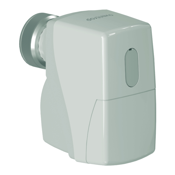
- Page 1 Valves, controls + systems Electromotive actuator „Aktor M ST L“, 24 V Operating instructions...
-
Page 3: Table Of Contents
„Aktor M ST L“ Contents Contents Seite General information ........................5 Validity of the operating instruction ...................5 Type plate ..........................5 Extent of supply ........................5 Contact ............................5 EU Declaration of conformity ....................5 Used symbols ..........................5 Safety-related information ......................6 Correct use ..........................6 Warnings ...........................6 Safety notes ..........................6... - Page 4 Contents „Aktor M ST L“ Reinstallation ........................11 Disposal ..........................11 Appendix ..........................12 101272584-V01.11.2019...
-
Page 5: General Information
The declaration of conformity can be obtained from the manufacturer. Validity of the operating instruction Used symbols These operating instructions are valid for the electro- motive actuator, 24V Aktor M ST L, 0-10V / 3 point control. Highlights important information and further explanations. Type plate... -
Page 6: Safety-Related Information
Safety-related information „Aktor M ST L“ Safety-related information Safety notes We have developed this product in accordance with The current standards, rules and guidelines apply. current safety requirements. Correct use Please observe the following notes concerning safe use. Operating safety is only guaranteed if the product is used correctly. 2.3.1 Danger caused by inadequately qualified... -
Page 7: Technical Description
„Aktor M ST L“ Technical description Technical description Functional description The actuator opens and closes a valve depending on Construction the applied control voltage. The actuator can be adapted to the specific param- 86,5 eters of the valve and to specific operational require- ments with the help of DIP switches. Technical data Operating voltage 24 V AC ±10 %, 50/60 Hz 24 V DC ±10 % Power consumption Dimensioning: - 3.7 VA (24 V AC) -
Page 8: Transport And Storage
Transport and storage „Aktor M ST L“ Installation Ambient tempera- 0 - 50 °C ture Initial installation Ambient humidity In operation: 0 - 85 % r.h., not condensing Make sure that there is enough space for the not in operation: 0 - 85 r.h., installation of the actuator. -
Page 9: Commissioning
„Aktor M ST L“ Commissioning Commissioning Connection of the power supply f Connect the power supply according to the desired Configuration of the DIP switches assignment in Illust. 6 on page 9 to Illust. 8 on page 10. f Remove the casing cover. 6.2.1 Steady control f Configure the DIP switches according to the valve used (see section 12 on page 12). -
Page 10: Point Control
Operation „Aktor M ST L“ Removal 6.2.3 2 point control 24 V AC/DC 0 V AC/DC Illust. 8: Pin assignment for 2 point control Illust. 9: Lift position indicator and valve stem cover 0 V AC/DC blue (BU) Lift position indicator of the actuator... - Page 11 „Aktor M ST L“ Reinstallation 11. Disposal 1. Completely disconnect the actuator from the power supply. 2. Check the lift position of the actuator. Directive 2012/19/EU WEEE: 3. If the actuator is not in the upper lift position (see position (1) in Illust. 10 on page 10):...
- Page 12 Appendix „Aktor M ST L“ 12. Appendix Settings of the DIP switches Valve + actuator = Model Control range DIP switches DIP switches Valve type S1 S2 S3 S4 S5 S6 S1 S2 S3 S4 S5 S6 DN 10/15 30 - 90 l/h...
- Page 13 „Aktor M ST L“ Appendix kvs = 0.45 0.25 U. 0.26 - 0.5 U 0.6 - 4 U. kvs = 1.0 0.5 - 1U. Cocon 2TZ 1.1 - 4.5 U kvs = 1.8 0.5 - 7 U. kvs = 4.5 0.75 - 1 U.
- Page 16 OVENTROP GmbH & Co. KG Paul-Oventrop-Straße 1 59939 Olsberg GERMANY 101272584 V01.11.2019 www.oventrop.com...
Need help?
Do you have a question about the Aktor M ST L and is the answer not in the manual?
Questions and answers