Table of Contents
Advertisement
Quick Links
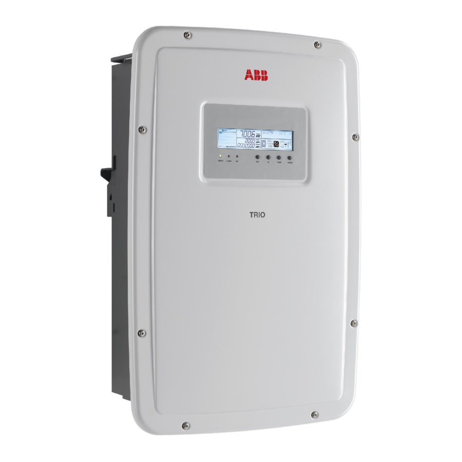
Solar Inverter
TRIO-5.8/7.5/8.5-TL-OUTD
Quick Installation Guide
In addition to what is explained in this quick installation guide, the safety
and installation information provided in the product manual must be read
and followed. The technical documentation for the product is available at
APPLY HERE
the website.
The device must be used in the manner described in the manual. If this
THE WIRELESS
is not the case the safety devices guaranteed by the inverter might be
ineffective.
IDENTIFICATION LABEL
Advertisement
Table of Contents

Summary of Contents for Fimer TRIO-5.8-TL-OUTD-400
- Page 1 Solar Inverter TRIO-5.8/7.5/8.5-TL-OUTD Quick Installation Guide In addition to what is explained in this quick installation guide, the safety and installation information provided in the product manual must be read and followed. The technical documentation for the product is available at APPLY HERE the website.
-
Page 2: Labels And Symbols
2 x 20 A 14.5 A sc max ac max (*): Up to 50 °C with Vdc>400 V IP65 Fimer S.p.A. 10 minutes -25 to +60 °C -13 to +140 °F Via Tortona, 25 - I 20144 Milano (MI) ATTENTION –... -
Page 3: Lifting And Transport
All installations at altitudes of over 2000 metres must be ENTER for the selected option (indicated by the > symbol) or to assessed case by case with the FIMER Service department. switch to the next digit to be edited. Installation position The operating parameters of the equipment are displayed through the display (01): warnings, alarms, channels, voltages, etc. -
Page 4: List Of Supplied Components
Differential sensitivity 300mA • Drill the 4 holes required using a drill with 10mm bit. The holes must be FIMER declares that the FIMER transformerless inverters, in terms of their about 70mm deep. construction, do not inject continuous ground fault currents and therefore •... - Page 5 10. Input configuration (DC) • Connection of inputs on models with disconnect switch The string connections for inverter versions equipped with DC disconnect switch (08) use quick fit connectors (multicontact or weidmuller), placed at The 7.5 and 8.5 kW power inverter versions are equipped with two the bottom of the mechanism.
- Page 6 13. Connection of the communication and control signals The following table shows the main components and the connections available on the control and communication board.. Each cable that must be connected to the communication card must go through the three service cable glands (16). Ref.
-
Page 7: Components And Accessories
15. Components & accessories The accessories can be bought separately and installed directly by a qualified technician or by the installer. For information on the installation, compatibility and use of the accessories, refer to the relevant part documentation. PMU EXPANSION BOARD ETHERNET EXPANSION BOARD Added features: •... - Page 8 With regard to purchase orders, the agreed particulars reproduction, disclosure to third parties or utilization of representative or visit: shall prevail. FIMER does not accept any responsibility its contents – in whole or in parts – is forbidden without whatsoever for potential errors or possible lack of prior written consent of FIMER.


Need help?
Do you have a question about the TRIO-5.8-TL-OUTD-400 and is the answer not in the manual?
Questions and answers