WM Systems M2M PRO4 Installation Manual
Hide thumbs
Also See for M2M PRO4:
- Installation manual (34 pages) ,
- User manual (73 pages) ,
- User manual (86 pages)

Related Manuals for WM Systems M2M PRO4


Summary of Contents for WM Systems M2M PRO4
- Page 1 M2M Router PRO4 ® Installation Guide v1.70 _________________________________________ 2021-04-12...
- Page 2 Document category: Installation Guide Document subject: M2M Router PRO4 ® Author: WM Systems LLC Document version No.: REV 1.70 Number of pages: Linux Kernel: 4.14.23 OpenWRT software version: 202011161...
-
Page 3: Table Of Contents
Table of contents CHAPTER 1. WIRING AND PREPARATION ............4 1.1 Description of interfaces ..................... 4 1.2 Safety declaration ......................5 1.3 Mounting, fixation ......................9 1.4 Cabling, wiring ........................10 1.5 Important notes ......................... 13 1.6 Understanding the LED signals .................... 13 CHAPTER 2. -
Page 4: Chapter 1. Wiring And Preparation
1. Wiring and Preparation 1.1 Description of interfaces ➢ 1 – Power supply connector ~100-230V AC, 50Hz (4-pins terminal block), pinout (left to right): L, N, -, PE ➢ 2 – micro SD card slot (for micro-SD card, for alternative micro-SD boot or data storage) ➢... -
Page 5: Safety Declaration
➢ 12 – ANT Main – Primary antenna connector, SMA-M, 50 Ohm antenna for 4G LTE connection ➢ 13 – ANT Diversity - Diversity antenna connector, SMA-M, 50 Ohm antenna (recommended to use for 4G LTE connection) 1.2 Safety declaration The device must be used and operated according to the related user manual. - Page 6 ■ Do not wear loose clothing that could get caught in the chassis. Fasten your tie or scarf and roll up your sleeves. ■ Wear safety glasses when working under conditions that might be hazardous to your eyes. ■ Do not perform any action that creates a hazard to people or makes the equipment unsafe. Safety with Electricity Follow this guideline when working on equipment powered by electricity.
- Page 7 Preventing Electrostatic Discharge Damage Electrostatic discharge (ESD) can damage equipment and impair electrical circuitry. It may occur if electronic printed circuit cards are improperly handled and may cause complete or intermittent failures. Always follow ESD prevention procedures when removing and replacing modules: ■...
- Page 8 Warning: Read the installation instructions before you connect the system to its power source. Statement 1004 Warning: This product relies on the building’s installation for short-circuit (overcurrent) protection. Ensure that the protective device is rated not greater than: 20A. Statement 1005 Warning: This unit is intended for installation in restricted access areas.
- Page 9 Caution: Be aware of the size and weight of the industrial router when mounting. Ensure that the mounting location has a stable flat surface and can safely support the weight of the device. 1.3 Mounting, fastening The device enclosure (unit) contains a DIN-Rail fixation due its case, which is to be intended to mount to DIN-35 rail or using a 3-point fixation by screws, or using the hook (in hanging position).
-
Page 10: Cabling, Wiring
➢ C – DIN-rail sleede for fixation ➢ D – DIN-rail position holder (release/fixate) ➢ E – Additional hooks for fixation to wall/mount Please note that close metal parts, the cabinet metal material and the industrial conditions as the usage of high rate power or other external gained radio frequency signals can cause radio signal disturbance and could cause weak wireless signal at reception or data transmitting or could cause less effective signal reception, weak wireless fidelity. - Page 11 3. Insert and push an activated mini SIM card to the SIM 1 titled tray (No. 4), top SIM holder. Insert by following the hints of SIM card figure for the proper orientation. (The SIM chip-side will be face down and the cutted edge towards to inside and push until it sleeves). 4.
- Page 12 The following cables are not part of the accessories of the delivered package. Use the following hints and the recommendation to choose useful cable and type to prepare the necessary connection(s) according to your requirements. AC cable (optional): The power cord 70 cm type, OMYA 4 x 1 mm^2, voltage Insulation min. 500 V, maintaining colors and ends with the power supply enabling connection to a 230V AC Function: ~100-230V AC power supply to the router Pins must be wired for usage: L (phase), N (null), -, PE (grounding) (see schematic for pinout)
-
Page 13: Important Notes
Connection type: 3-pins terminal block Pinout (from left-to-right): Ex3 (M-), Ex2 (M+), Ex1 (COM) RS485 Function: M-Bus connection, up to max. 30 external devices MBUS* Digital inputs: Cable type: 3 + 3x LgY 0.75 mm2, signed by color, blanked cables for data connection Connection type: 3-pins terminal block Pinout (from left-to-right): DI1 (input #2), DI0 (input #1), GND (ground) -
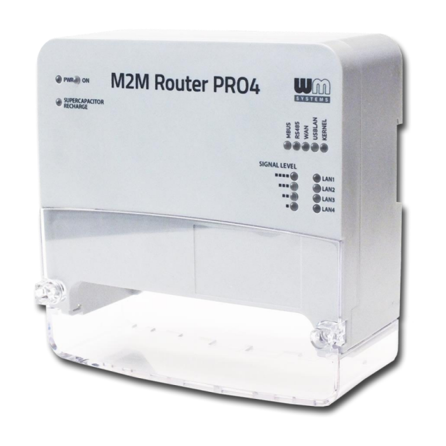
Page 14: Understanding The Led Signals
• When configuring the SIM or APN settings, after the saving the device, it will not restart the modem automatically with the new settings. You need to restart the modem by the Restart button in the OpenWrt ® menu at Network / Modem settings. 1.6 Understanding the LED signals The router has 16 LEDs to assign the device’s current status, communication, physical connection. - Page 15 The power indication group (group A) and signal level leds (group C) are is fixed, but the other 9 LEDs (group B and group D) are free to reonfigurable.
-
Page 16: Chapter 2. Installing The Device
Chapter 2. Installing the device 2.1 The very first startup The router has a super-capacitor component insidem, which can protect the device against the possible short (<5sec) power outages. Therefore this component can be charged and it can be exhausted after an outage or if you store the device for months without connecting power source or using. -
Page 17: Normal Startup
Next time you don’t need to push the Reset. You can stop the device anytime by removing the power source and start the device by adding the AC power on. 2.2 Normal startup The router has a pre-installed system (which contains the firmware and the pre-configured OpenWrt ®... - Page 18 c.) The MBUS, RS485, WAN, USBLAN leds will be flashing during 30 seconds until boot. d.) At the end of the boot process, only the WAN, USBLAN leds are flashing for 5-10 seconds.
- Page 19 e.) When the connectivity LEDs are not blinking anymore the load of the system has finished. f.) If the WAN (APN) interface was not configured yet, the SIGNAL LEVEL low LED is blinking which means the router tries to connect to the wireless network. If it will was configured properly (APN, password and SIM PIN is matching) and the registration was succesful, then the WAN led will be lighting and the current SIGNAL LEVEL leds will be also lighting its signal strength value which means connected and you have useful wireless signal reception...
-
Page 20: Local Access Via Ethernet
2.3 Local access via Ethernet port (LAN1..LAN4 interfaces) The default Ethernet IP address of the device is 192.168.1.1 Add the 192.168.1.x IPv4 address (where x can be between 2 and 255) to your computer’s Ethernet interface for connecting to the device. Then you can access the device through the web user interface or by SSH. -
Page 21: Web User Interface And Login
2.5 Web user interface and Login 1. The router’s local web user interface (LuCi ® ) is reachable through the Ethernet or USB interface – on the default addresses. Attention! For accessing the web user interface we recommend to use the Mozilla Firefox ®... - Page 22 5. The OpenWRT ® system’s LuCi ® web interface has loaded into your browser. Now fill the Username and Password fields and click on the Login button for the entry. root wmrpwdM2M Username: Password:...
-
Page 23: Ssh Access
2.6 SSH access The router can be accessed through SSH connection, when it is available on its IP address – by a putty terminal utility (e.g. the tool). Putty is a free tool which can be downloaded from the following URL: https://www.chiark.greenend.org.uk/~sgtatham/putty/latest.html The device can be accessed by SSH on the 192.168.1.1:22 (port nr. -
Page 24: Wireless Access
The operating system uses the embedded Micro uCLinux, kernel 4.4 version, therefore you can use UCI Command line interface standard and compatible Linux commands or the – check command line compatibility before using the commands here. You can get more information about using the UCI ®... - Page 25 4. Soon the wireless module will be configured regarding the settings. Now the device will try to connect and register the SIM card to the network. The availability of the mobile network is assigned by the WAN LED (lighing by green). When it has sucessfully registered to the given APN, the WAN LED will lighting by green and the SIGNAL LEVEL will be also signed according to the signal reception (it is lighing by green).
-
Page 26: Led Indication
2.8 LED indication The default LED signal indication is listed here. The B-C-D group of LEDs can be changed if you need in the OpenWrt ® web interface. Description Colour Reconfigurable No light Flashing Continously light Group A No power AC Power supply OK No / FIXED Device power supply... -
Page 27: Power On / Supercap Charging Mode
Group C Cellular network signal strength 4 signal – Signal is above 97dBm (very good reception) SIGNAL LEVEL 3 signal – Signal is above 85dBm (average reception) (◼◼◼◼,◼◼◼,◼◼,◼) 2 signal – Signal is above 65dBm (poor reception) 1 signal – Signal is below 50dBm (weak reception) 0 signal –... - Page 28 No Power supply / Power supply removed / Power line outage If the AC power supply was removed or in case of a detected electricity / power outage, after min. 5 seconds the device will be disconnecting all interfaces, file systems, micro-SD card and afterall will be shutdown.
-
Page 29: Service Features
2.10 Service features The device has various service features which can be controlled manually - just for the case – which can be initiated by pushing the Reset button (no. 11). stop start By any reason, if you need to the device immediately or you cannot login into the system, you can start or stop it manually here. - Page 30 MENU ITEM 3 (3x short push) – exit from menu Then after the selection, the choosed menu item number is flashed by the KERNEL led (e.g. flashing twice in case of selecting the MENU ITEM 2). Then you need to confirm the choosen menu item for executing by a longer 6sec Reset push.
-
Page 31: Chapter 3. Device Configuration (Main Important Settings)
3. Device configuration (main important settings) Important! The device uploaded by a pre-configured system. Check the configuration, and if the settings are not match with your expectations, please change the configuration settings and save them. The device will be automatically apply your settings. When you have logged in, at the startup screen (Status/Overview) the web interface can be seen with all relevant information and the current status of the device. - Page 32 You can configure the cellular network connection and APN/password (for SIM), Ethernet IP address, etc.). SIM/APN settings: In the OpenWrt menu, choose the Network / Interfaces menu, interface, Edit button. (You can also use the Network / Modem settings.) Mobile Operator 1.
-
Page 33: Chapter 4. Support
4. Support 4.1 Contact support If you have any questions concerning the usage of the device, contact us at the following contact: E-mail: iotsupport@wmsystems.hu Phone: +36 20 3331111 Online product support can be required here at our website: https://www.m2mserver.com/en/support/ For the proper identification of your device, use device sticker and its information, which contains important information for the call center. -
Page 34: Chapter 5. Legal Notice
WM Systems LLC., with clear indication of the source. The pictures in the user guide are only for illustration purposes. WM Systems LLC. does not confirm or accept responsibility for any mistakes in the information contained in the user guide.
Need help?
Do you have a question about the M2M PRO4 and is the answer not in the manual?
Questions and answers