WM Systems M2M PRO4 MODEM Installation Manual
Hide thumbs
Also See for M2M PRO4 MODEM:
- User manual (73 pages) ,
- User manual (86 pages) ,
- Installation manual (34 pages)

Subscribe to Our Youtube Channel
Related Manuals for WM Systems M2M PRO4 MODEM


Summary of Contents for WM Systems M2M PRO4 MODEM
- Page 1 M2M PRO4 MODEM ® Installation Guide v0.92 _________________________________________ 2020-02-17...
- Page 2 Document specifications This document was made for the M2M PRO4 MODEM ® device and it contains all relevant installation steps of the device. Document category: Installation Guide Document subject: M2M PRO4 MODEM ® Author: WM Systems LLC Document version No.: REV 0.92...
-
Page 3: Table Of Contents
Table of contents 1. WIRING AND PREPARATION ................ 4 1.1 Description of interfaces ..................... 4 1.2 Safety declaration ......................4 1.3 Mounting, fixation ......................8 1.4 Cabling, wiring ........................9 1.5 Important notes ......................... 12 1.6 Understanding the LED signals .................... 13 2. -
Page 4: Wiring And Preparation
1. Wiring and Preparation 1.1 Description of interfaces 1 – ~100 - 240V AC power input plug (4-pins terminal block), the pinout from left-to-right is the following: L, N, -, PE 2 – micro USB connector (PC connection - for configuration, alternative DC power input) ... - Page 5 It is also prohibited to remove or modify the device PCB. The modem and it’s parts must not be changed by other items or devices. Any modification and repairation is not allowed without the permission of the manufacturer. It all causes the loss of product warranty. Caution! Only a certified expert or the manufacturer is allowed to open the enclosure! By general the device is using AC mains.
- Page 6 ■ Disconnect all power before: – Installing or removing a chassis – Working near power supplies ■ Look carefully for possible hazards in your work area, such as moist floors, ungrounded power extension cables, frayed power cords, and missing safety grounds. ■...
- Page 7 Warning! IMPORTANT SAFETY INSTRUCTIONS This warning symbol means danger. You are in a situation that could cause bodily injury. Before you work on any equipment, be aware of the hazards involved with electrical circuitry and be familiar with standard practices for preventing accidents. Use the statement number provided at the end of each warning to locate its translation in the translated safety warnings that accompanied this device.
-
Page 8: Mounting, Fixation
Warning: Only trained and qualified personnel should be allowed to install, replace, or service this equipment. Statement 1030 Warning: Ultimate disposal of this product should be handled according to all national laws and regulations. Statement 1040 Warning: To prevent the system from overheating, do not operate it in an area that exceeds the maximum recommended ambient temperature of: Statement 1047 Warning: Installation of the equipment must comply with local and national electrical codes. -
Page 9: Cabling, Wiring
Figure of bottom side of the unit enclosure A – Device housing case back plate B – Hook for fixation to wall/mount C – DIN-rail sleede for fixation D – DIN-rail position holder (release/fixate) E – Additional hooks for fixation to wall/mount 1.4 Cabling, wiring 1. - Page 10 You can use 4G LTE wireless antenna with 3-6dB, 9dB or more gained versions. RG174 cable SMA antenna with magnetic mount can be used for external usage. The antenna must be placed and oriented that it should has a some clearance in any direction.
- Page 11 6. By default, the modem has an installed OpenWRT ® operating system which is ready to use and configure to your SIM card APN and for you usage requirements. 7. Plug the 100-240V AC power supply connector to the 100..240V AC interface (No. 1), then plug the power cable to the external electricity plug –...
-
Page 12: Important Notes
microUSB-USB configuration cable: Type: microUSB–to–USB cable Connector type: USB 2.0 micro Type-B connector Function: for configuration – connecting the device to a computer or provide alternative power source: DC power (5V DC) Schematic figure of wiring, interfaces, pinout 1.5 Important notes ... -
Page 13: Understanding The Led Signals
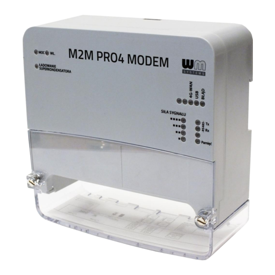
1.6 Understanding the LED signals The device has 16 LEDs to assign the modem’s current status, the communication, connection. These LEDs are located in four groups: Operation status LEDs (Group A) MOC – Power source connected / mains on WL – The modem has started LADOWANIE SUPERCONDENSATORA (in case of exhausted super-capacitor part which shows the process of the recharge –... -
Page 14: Installing The Modem
Installing the modem 2.1 The very first startup The modem has a super-capacitor part inside, which protect the device against possible shorter power outages. It can also provide RTC backup for the device, up to 2 days. Therefore, this supercap component can be charged and it can be exhausted after an outage or if you store the modem for months without connecting power source or using. - Page 15 Start the modem by the following sequence. 1. Ensure that you have inserted an activated SIM card into SIM holder (No. 3) in the right position. The usage of SIM holder is obligatory for using the wireless communication. 2. Ensure that antenna is mounted to the SMA interfaces (No. 6). 3.
- Page 16 d.) At the end of the boot process, only the 4G-WAN, USB leds will be flashing for 5-10 seconds. e.) When the connectivity LEDs are not blinking anymore the load of the system has been finished. f.) The SILA SIGNALU (SIGNAL LEVEL) low LED(s) are blinking which means the modem tries to connect to the wireless network.
-
Page 17: Local Access Via Usb
h.) The RS485 RX led (in case of meter data receive) or the RS485 TX led (in case of sending data to the meter) will be active – which signs the data traffic, modemmeter activity. When the USB led is active during the load of the system, this signs that the device is already accessible on its USB interface –... -
Page 18: Web User Interface And Login
2.4 Web user interface and Login 1. The modem’s local web user interface (LuCi ® ) is reachable through the Ethernet or USB interface – on the default addresses. Attention! For accessing the web user interface we recommend to use the Mozilla Firefox ®... - Page 19 5. The OpenWRT ® system’s LuCi ® web interface has loaded into your browser. Now fill the Username and Password fields and click on the Login button for the entry. root Username: wmrpwdM2M Password:...
-
Page 20: Ssh Access
2.5 SSH access The modem can be accessed through SSH connection, when it is available on its IP address – by a putty terminal utility (e.g. the tool). Putty is a free tool which can be downloaded from the following URL: https://www.chiark.greenend.org.uk/~sgtatham/putty/latest.html The modem can be accessed on SSH at the 192.168.10.1:22 (port nr. - Page 21 Edit 1. Choose the Network / Interfaces menu, interface, button. 2. Add the SIM #1 APN (APN setting of your SIM card)
- Page 22 3. If you have PIN code on the SIM card that you are using, add the right PIN here. (Ask your Mobile Operator about the SIM info.) username password 4. If that is necessary to use (SIM #1 PAP/CHAP username) or (SIM #1 PAP/CHAP password) for the wireless network access, consult with your mobile provider and change the settings here, please.
-
Page 23: Led Indication
If the module with the SIM card was connected, the module is immediately generating data Rx/Tx traffic on the network where the values will be continously growing/changing for the Interface status at the Interfaces / Interface Overview part for the interface. -
Page 24: Power On / Supercap Charging Mode
Group D Outgoing data Yes, Programmable RS485 data transmission flow, data RS485 TX (transmit: TX) transmitting via the RS485 port Incoming data RS485 RX Yes, Programmable RS485 data reception flow, receiving (receive: RX) data via the RS485 port Yes, Programmable Inactive Data read from No activity at flash... - Page 25 This plus operation time is possible due to the internal super-capacitor component – which provides safe backup power for short time outages. During the shutdown process only the WL (ON) LED will be lighting by green, but the MOC (Power) LED will be blank. When the shutdown process has been finished, all LEDs will be inactive.
-
Page 26: Service Features
2.9 Service features The modem has various service features which can be controlled manually - just for the case – which can be initiated by pushing the Reset button (no. 5). stop start By any reason, if you need to the device immediately or you cannot login into the system, you can start or stop it manually here. - Page 27 Then after the selection, the choosed menu item number is flashed by the BLAD led (e.g. flashing twice in case of selecting the MENU ITEM 2). Then you need to confirm the choosen menu item for executing by a longer 6sec Reset push. Some examples: a.) RESTART the modem: - The modem must be operating...
-
Page 28: Alternative Installation Of The Openwrt System
® 2.10 Alternative installation of the OpenWrt system Pro4 Modem By default, we deliver the device with the pre- installed OpenWrt ® system. But, if it is necessary, the device can be reinstalled from a connected USB stick, through an OTG cable micro-USB to USB-A) The device firmware must be written to a USB drive/stick by the Win32 Disk Imager... -
Page 29: Modem Configuration (Main Important Settings)
3. Modem configuration (main important settings) Important! The modem has been uploaded by a pre-configured system. Check the configuration, and if the settings are not match with your expectations, please change the configuration settings and save them. The modem will be automatically apply your settings. When you have logged in, at the startup screen (Status/Overview) the web interface can be seen with all relevant information and the current status of the modem. - Page 30 You have to configure the 4G connection and APN/password (for SIM). SIM/APN settings: In the OpenWrt menu, choose the Network / Interfaces menu, interface, Edit button. Mobile Operator 1. Ask your about the SIM card information. 2. Add the SIM #1 APN settings according the SIM card info – ask with your mobile provider. username password 3.
-
Page 31: Support
4. Support 4.1 Contact support If you have any questions concerning the usage of the device, contact us at the following contact: E-mail: iotsupport@wmsystems.hu Phone: +36 20 3331111 Online product support can be required here at our website: https://www.m2mserver.com/en/support/ For the proper identification of your device, use modem sticker and its information, which contains important information for the call center. -
Page 32: Device Data, Certification
6. Device data and certification 5.1 Datasheet of the device • Dual Power / Mains: AC power supply from 100..240V AC, 50 Hz, Voltage / Current 600mA current / alternative 5V DC mains (via USB powered conn.) Power Consumption • Average: 3-4W • Max.: 10W •... -
Page 33: Wireless Module Certification
5.2 Wireless Module certification... -
Page 34: Legal Notice
WM Systems LLC., with clear indication of the source. The pictures in the user guide are only for illustration purposes. WM Systems LLC. does not take care the responsibility for any mistakes in the information contained in the user guide.
Need help?
Do you have a question about the M2M PRO4 MODEM and is the answer not in the manual?
Questions and answers