WM Systems M2M User Manual
Industrial router 2 dcu mbus
Hide thumbs
Also See for M2M:
- User manual (9 pages) ,
- Installation manual (34 pages) ,
- User manual (79 pages)

Related Manuals for WM Systems M2M


Summary of Contents for WM Systems M2M
- Page 1 User Manual M2M Industrial Router 2 DCU MBUS ___________________________________________________ Rev: 1.00 2023-02-10...
- Page 2 Document specifications This document was completed for the M2M Industrial Router 2 DCU MBUS device ® and contains the hardware specification, with the most important information and software settings of the device. Document category: User Manual Document subject: M2M Industrial Router 2 DCU MBUS ®...
-
Page 3: Table Of Contents
Table of contents CHAPTER 1. Product information ..................5 CHAPTER 2. Technical data ....................5 2.1 Power voltage / Current ratings .............................. 7 2.2 Cellular modules (order options) ............................7 CHAPTER 3. Device exterior design and appearance ............9 3.1 Safety cautions ....................................10 3.2 Mounting, fastening .................................. - Page 4 8.8 Port Forward settings ................................... 43 8.9 IP routing, NAT settings ................................45 8.10 Dynamic DNS settings ................................46 CHAPTER 9. Special settings ....................47 9.1 Ping an IP address .................................... 47 9.2 Network Time Service (NTP) ..............................48 9.3 TFTP settings ....................................... 48 9.4 LED configuration ...................................
-
Page 5: Chapter 1. Product Information
Reliable and Rugged Communication Device for Smart Grid and Industrial Applications. This Data Concentrator is designed for use in various smart grid and industrial M2M / IoT applications, including Automated Metering Infrastructure (AMI) and industrial automation projects. The DCU is capable of reading Modbus registers from connected PLCs and data from up to 30 MBus meters. - Page 6 Secure storage / Secure Boot The device has a built-in eMMC chip (4 or 8 GByte storage – by order option) for Secure Boot process / encrypted storage of all customer data. It uses an OTP-enabled memory chip. The device is secured with Secure Boot system and secure storage mechanism. It uses an SHA-256 encrypted file system (with RSA and SHA-256 assigments).
-
Page 7: Chapter 2. Technical Data
Chapter 2. Technical data 2.1 Power voltage / Current ratings • Power Voltage / Ratings: • 12V DC, 1A power supply (9-32VDC) – powered via Microfit 4-pins power input connection (from external 12V DC power adapter) • Current / Consumption: Average: 200mA - 260mA, 12VDC (according to module version) / 2.4W –... - Page 8 Bands: o LTE Cat.M / 450MHz: B1/B2/B3/B4/B5/B8/B12/B13/B14/B18/B19/B20/B25/ B26/B27/B28/B31/B66/B72/B85 o LTE Cat.NB: B1/B2/B3/B4/B5/B8/B12/B13/B18/B19/B20/B25/B26/B28/B31/ B66/B85 o GSM/EGPRS: 850/900/1800/1900MHz...
-
Page 9: Chapter 3. Device Exterior Design And Appearance
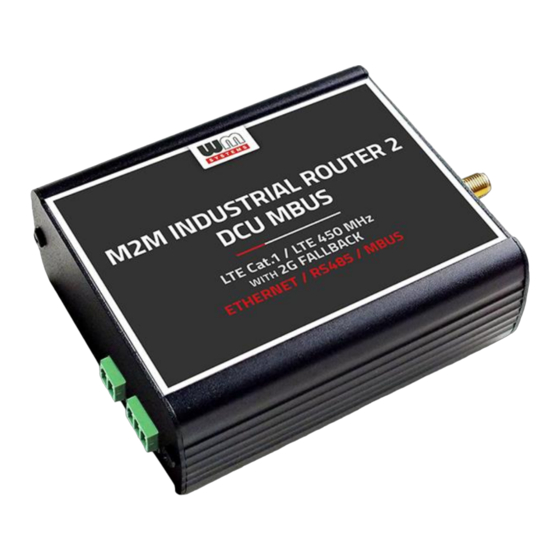
Chapter 3. Device exterior design and appearance Industrial DCU, assembled in aluminum casing with interface connectors / ports 1 – POWER (9-32V DC): Microfit 4-pin power connector (for DC power/adapter) 2 – *SIM card slot (2FF) 3 – micro-USB connector (for configuration) 4 –... - Page 10 Industrial DCU MBUS with Mbus and RS485 / Modbus connectors Industrial DCU MBUS, assembled in aluminum casing, attachable to 35mm DIN rail (with an adapter)
-
Page 11: Safety Cautions
Safety cautions The device must be used and operated according to the user manual provided. Only a responsible and skilled person with adequate experience and knowledge in wiring and installing a DCU device, as instructed by the service team, should carry out the installation. - Page 12 ■ Avoid actions that could cause a hazard to people or equipment. Safety preucations for Electricity ■ Read all safety warnings before working on equipment powered by electricity. ■ Locate the emergency power-off switch for quick access in case of an electrical accident.
-
Page 13: Mounting, Fastening
■ Wear an ESD-preventive wrist strap and connect it to an unpainted surface of the chassis frame to safely channel ESD voltages to ground. ■ If a wrist strap is not available, ground yourself by touching a metal part of the chassis. -
Page 14: Further Accessories
In these cases, we recommend testing the wireless signal reception and quality. If necessary, you can improve reception by using an external magnetic mount antenna that is mounted outside of the cabinet and placed on its surface. 3.4 Further accessories The following accessories are not part of the product, these are order options. - Page 15 RS485 cable: You should use the following cable type: 70 cm OMYA type, 3 x 0,75 mm^2, halogen- free, double insulated wire pair, up to min. 24V DC breakdown voltage, colour signed cabling, blanked on the cable end – for supporting the 24V DC power voltage.
-
Page 16: Chapter 4. Software System
DCUSs from this program, allowing for remote control and execution of tasks on the device. In the Device Manager software, individual or group settings can be made. Legacy or TLS communication can also be allowed in the Device Manager software during the M2M Industrial Router 2's communication. -
Page 17: Tls Protocol Communication
4.4 TLS protocol communication TLS v1.2 protocol communication can be activated between the DCU and the Device Manager from the software side, by choosing TLS mode or legacy communication. ® The device uses the mbedTLS library and the Device Manager (DM) uses the ®... -
Page 18: Chapter 5. Starting The Device
Chapter 5. Starting the device 5.1 Connecting the DCU 1. Ensure that the DCU is not under power voltage, therefore the power adapter cable is removed from the POWER titled microfit connector (1) – or the adapter is not connecting to the power network. Ensure, that all the 3 LEDs (7) are blank. 2. -
Page 19: First Start
6. Connect the RS485 device, Modbus meter, etc- to the RS485 port (8) to receive the data of the external device or meter. 7. Connect Mbus device(s) you want to read out to the MBus port (9) to receive the data of the external device(s). - Page 20 8. If you’d like to make the DCU settings via USB connection (micro-USB port) then install the USB Ethernet / RNDIS Gadget driver to your computer by using your browser: https://m2mserver.com/m2m-downloads/RNDIS_win10.ZIP 5.3 Web user interface of the DCU To connect to the DCU, allow the device IP address for the Ethernet connector interface in the Windows ’s network settings (IP address for Ethernet...
- Page 21 In case of USB connection, you have to setup the USB Ethernet / RNDIS Gadget virtual interface to the following IP: 192.168.10.100, subnet mask: 255.255.255.0 Open the DCU’s local website in an internet browser. By default, the web user interface (LuCi) URL on Ethernet port: https://192.168.127.1 On the USB connection the URL is: https://192.168.10.1...
-
Page 22: Access Via Ssh Connection
Attention! Don’t forget to change the login password before connecting the router to the public cellular network! Push to the Login button. 5.4 Access via SSH connection The DCU can be accessed through ssh connection also, when it is available on its IP address –... - Page 23 To review the UCI commands and options that can be used, we recommend to read UCI Reference Guide, which can be downloaded from our website. https://m2mserver.com/m2m-downloads/UCI_Command_Line_Reference_v3.pdf E.g. you can make a query to ask the current setting of a service (openvpn, ser2net, ddns, etc.
-
Page 24: Chapter 6. Web Administration User Interface
Chapter 6. Web Administration user interface 6.1 Dashboard (Main page) After login to the web interface, the startup screen appears with the current status of the DCU. At the System part you can check that the Firmware version. It should be 202302061 or newer version. - Page 25 The Local Time shows the currently received time, the Uptime shows the spent time since the last reboot/start. At the Modem part you will find the SIM info (SIM ID). There the Operation mode and Access Technology values will inform you about the current status of the cellular connection.
-
Page 26: Menu
6.2 Menu By the menu you can access the following features: Status – Status data, operation and system log, operation monitoring System – System settings, administration, software and firmware refresh, backup/restrore of the configuration settings, LED configuration, reboot, etc. Services – Dynamic DNS settings, ser2net settings (RS485) Network –... -
Page 27: Services Menu
• Clone config backup / restore – here you can make a file of the current settings which can be distributable to an another DCU device • Installation of further Software (3rd party tools, applications) from the online software repository •... -
Page 28: Network Menu
6.6 Network menu • Here you can configure the settings of each network Interfaces. • Routing – static route paths can be also defined here. • You can modify the DHCP and DNS settings. • Diagnostics - you can test network operation and connection health (ping IP address). -
Page 29: Chapter 7. Important Notes
Chapter 7. Important notes • For security reasons, we do recommend to change the password immediately for accessing the administration user interface (local webpage). Read Chapter 9.6 for detailed settings. • Some protocols are disabled by default on the DCU, but most of them you can enable to use: o The DHCP service is turned off by default. - Page 30 Status / Firewall menu section is an excellent option for scanning through traffic and the Network / Firewall menu, where you can add new rules or modify existing ones. o Please check the network traffic of the DCU frequently in the Status / Firewall menu (port number, incoming IP, especially outgoing data traffic and downloaded data).
-
Page 31: Interface Settings
Chapter 8. Network configuration of the DCU 8.1 Interface settings The list of the available network interfacescan be found at the Interfaces menu item. The network interfaces are listed at the Interface part. interface means (eth0) the Ethernet port connection, the USBLAN is the USB-Ethernet (usb0) and the... -
Page 32: Cellular / Mobile Internet Settings
8.2 Cellular / mobile internet settings Open the item from the upper selection. Then at the General Settings tab you can see the current status of the interface and the transmitted data amount. Setup the module for connecting to the LTE or Cat.M / Cat.NB cellular network (according to the assembled module type) –... - Page 33 The PAP/CHAP username and PAP/CHAP password settings can be also configured here – if it is required for the connection. Attention! The available APN settings will be provided by the SIM card provider mobile operator or your mobile internet service provider. Click to the Save button for saving the settings, while the devices attempts then...
-
Page 34: Ethernet (Lan) Settings
Data traffic from the interface (mobile network) is indicated by a fast green flashing of LED2. You can find further network settings at Advanced Settings tab. 8.3 Ethernet (LAN) settings For the interface, at the LAN menu item at the Network Interfaces menu item at the LAN interface button. - Page 35 We recommend that you change the device's default 192.168.127.1 address (IPv4 address) to a custom IP address, depending on your subnet - or the way you want it to be served by the DCU device. Also check IPv4 netmask field to make sure it is appropriate for the class you want to use.
-
Page 36: Dhcp, Dns Settings
8.4 DHCP, DNS settings The DHCP service allows the automatic IP address providing for the connecting devices in the current IP segment by the DCU. The DHCP settings can be found at the Network / Interfaces menu (according to the required interface). - Page 37 Further DHCP settings can be achieved at the Network menu, at the DHCP and DNS item, General Settings tab. At the Static Leases tab, you can see the list of the devices, which given their IP addresses from the DCU’s DHCP service (with the renewal lease time).
-
Page 38: Dns Settings
Here you can devices to always provide the same dedicated IP address by the device. This can be required by adding values to the Hostname, the MAC-Address and the IPv4-Address. Save your settings by the Save button. 8.5 DNS settings You can configure the DNS service from the Network / DHCP and DNS menu, with chossing the Advanced Settings... -
Page 39: Defining The Route Rules
At the DNS server port field you can define the port for the DNS service (by default its port number is 53). When you have modified the settings, save them by the Save button. 8.6 Defining the route rules In the Network / Routing menu you can define the rules for the current routing. You can define a new one by the button. - Page 40 Therefore, we offer to check network traffic on the DCU: connections, communication channels (port number, incoming IP) and to listen incoming and outgoing network activities! You can check these in Status / Realtime Graphs menu at Connections tab – where these can be listed.
- Page 41 Another method for limitation can bve the whole disabling with opening and enabling only necessary communication ports, IP-segments or allowing exact IPs. You can modify firewall settings at Network / Firewall menu, General Settings tab. For first, the communication rules are listed here with the directions and operation of the communication rules.
- Page 42 Here, you can see and modify the general rules of the communication, at the Input (incoming), Output (outgoing) and Forward operations one by one by accept it, or reject, drop. You can Delete the settings or modify. At the Zones part you can a new rule to the current ones.
- Page 43 At the Advanced Settings tab you can limit the incoming, outgoing, and forwarded traffic for each subnets. When you have modified the settings, save them by the Save button. The firewall can be configured by default to allow or tilt the communication – according to the chosen settings.
-
Page 44: Port Forward Settings
8.8 Port Forward settings Here in the Network / Firewall menu, Port Forwards tab you can setup, that which port forwarding rules should be valid. Here you can add the necessary ports and IP adresses. - Page 45 You can define the necessary port and IP address. Or you can add a new rule by the button. When you have modified the settings, save them by thevSave button.
-
Page 46: Ip Routing, Nat Settings
8.9 IP routing, NAT settings In the Network / Firewall menu, at Traffic Rules tab you can setup the Traffic Rules. You can add a new rule by the button. When you have modified the settings, save them by the Save button. -
Page 47: Dynamic Dns Settings
vulnerability. It's a good idea to set the rules so that only the most necessary services and ports can distribute data on the network. 8.10 Dynamic DNS settings In the Services / Dynamic DNS menu you can allow the DDNS service providing and the IP address of the DDNS. -
Page 48: Chapter 9. Special Settings
M2M APN zone). In case of M2M APN the 192.168.1.250 address can be accessed, it is possible to ping the address for checking the 3G network connection. -
Page 49: Network Time Service (Ntp)
9.2 Network Time Service (NTP) Open the System / System menu, Time Synchronisation part. You can add hereby the refresh interval at the Update interval (in seconds). Enable or disable the NTP service at the Enable NTP client function (when receiving time data) and provide NTP time to connected devices (Provide NTP server). -
Page 50: Led Configuration
Of course, you can also use SFTP on your DCU by sending the data to IP addresses by entering your account and password information. if you need more help, see the OpenSSH Linux command line settings. If you have modified the settings, save by Save button. - Page 51 You can add a LED with its action by the button. You can also setting. You can the current settings. From the Trigger list, you can select which event to affect. E.G. for netdev, indicates the status of the network connection, and under Device, you can specify which interface it applies to.
-
Page 52: Remote Access (Ssh)
9.5 Remote access (SSH) The device can be accessed remotely, including its settings - which you can change remotely. Remote access is via the mobile network, the IP address range of the SIM card. Therefore, the device must be on the public Internet or in the same zone from which you want to access the device. -
Page 53: Uci Usage From The Command Line
To review the useable UCI commands and options that can be used, we recommend to read the UCI guide, which can be downloaded from our website: https:// m2mserver.com/m2m-downloads/UCI_Command_Line_Reference_v3.pdf 9.7 IPSEC settings Open the Systems / Startup menu to enable strongSwan IPSec feature. -
Page 54: Vpn Client (Openvpn) Configuration
Then push to the button of the line of the IPSec service to start the feature. Configure the strongSwan IPsec service through ssh connection, from command line. Read the OpenWrt website for more information on possible IPSec settings: https://openwrt.org/docs/guide-user/services/vpn/ipsec/strongswan/start 9.8 VPN client (OpenVPN) configuration First you have to start the OpenVPN service. - Page 55 Then push to the button of the line of the „opevpn” service to start the feature. Open the VPN / OpenVPN menu, where you can set up an OpenVPN connection. The OpenVPN service default port nr. is 1194. You will find three pre-configured VPN connections that you can enable or change your settings.
- Page 56 So, choose any profile from the ones listed - e.g. the sample_client profile - that is, the VPN client, then press the button to edit. The following window will appear, where you can set the following: Configure at least the next fields on this page: proto (Protocol): here define the connection type –e.g.
- Page 57 The TLS v1.2 communication settings here can be made. The TLS settings should be made at the Device Manager side. Save the configured settings by the Save button. Then return to the OpenVPN menu, where you can enable the given setting with the Enable option, then press the button to start the configured VPN connection, then press the...
-
Page 58: Rs485 / Modbus Settings (Ser2Net)
For the proper settings, we offer to read the related tunelling service description of the OpenWrt administration interface which you are currently using: ® https://wiki.openwrt.org/doc/howto/vpn.openvpn#tab__traditional_tun_server1 OpenVPN settings can also be configured using the openVPN daemon on the Linux side using the UCI - from the command line - using SSH. Some examples of its use: You can make a query to ask the current OpenVPN settings: #uci show openvpn... - Page 59 Then wait until the service list will be refreshed and the „ser2net” will be listed as an service. Then push to the button of the line of the „ser2net” service to start the feature.
- Page 60 To configure the RS485 / Modbus port, open the Services / Ser2net menu. At the Proxies tab you can define the properties of the incoming transparent data transmission. Make sure that Global Switch option is Enabled. At the Default settings part, you should configure the following parameters: Baudrate (default is 9600 bps for the RS485) can be defined between 300 bps and 19 200 bps.
- Page 61 Stopbit value can be 1 or 2 Parity value can be Even, Odd or None At the Proxies tab, enable the RS485 option to activate the communication. Make sure that the service option is Enabled.
- Page 62 Then define the Service Port number (which is port no. 5000 by default). At the Protocol field, the data format can be choosen: - off: no data stream - raw: full duplex - rawlp: one-way communication - telnet: for further use For Timeout value, you can specify the amount of timeout (in seconds) –...
-
Page 63: Mbus Settings
Note, that you should add the specified RS485 port number to the Firewall rules (Network / Firewall menu), otherwise the DCU may not receive any data. You can also connect an IIoT IO/RS485 concentrator to collect input signals, readout status of digital inputs. More info: https://m2mserver.com/en/product/iiot-io-data-concentrator-16di/ 9.10 Mbus settings... -
Page 64: Run Commands Remotely (Sms Config Settings)
Press the Save button to save the settings. 9.12 Run commands remotely (SMS config settings) You can execute commands on the DCU remotely when an SMS message was sent to the device’s SIM phone number. To set these remote control commands, open the Network / SMS Config menu. First you can see the Phone Book where you can define or phone number(s). - Page 65 At the SMS commands part you can choose preset commands by selecting them for the number. In the case of an SMS from a preset phone number, the DCU runs the preset command (s) assigned to the phone number: e.g. Reboot For other commands, the DCU returns the information in a reply SMS message (e.g.
-
Page 66: Firmware Refresh
Chapter 10. Software refresh, maintenance 10.1 Firmware refresh 1. Open the System menu, Backup / Flash firmware item. 2. At the bottom part, push to the button. 3. Browse the fw-…. compressed firmware file and push to the button. 4. Then an nother window is loaded, where the checked file is checked for approx. in half a minute. -
Page 67: Installing Applications
6. Then the next message appears on the screen in the browser. Then the refresh method has started, while the LED3 is continuously lighting by and sometimes the LED2 is flashing. 7. At the end of the installation - the LEDs will no longer flash - the system will reboot 2x, then the OpenWrt system will start and load as described. - Page 68 First you have to push the button and setup the software distribution configuration in the popup windows, where you have to define the path of the installation packages are stored. Then the settings by the button. Afterall, push to the button to refrest the available software catalog - from the software repository.
- Page 69 Important! This feature is available when the public internet can be accessed by the SIM card, APN zone. If you want to install a local package from the DCU then push to the Upload Package button. You can check the Installed packages also.
-
Page 70: Restarting The Device
The installed software packages are listed under Status with their Version information. You can now configure and use the installed Linux program. You can configure or run it from the command line using the SSH terminal window. (Staying with our example: type "mc"... - Page 71 Then the DCU will be operating as normal, and will be connected to the internet according the configuration settings. Instead all of these, you can restart the DCU by pushing its Reset button on its interface / port side. Push this button for 10 seconds, by a sharp and thin object. Then the device will be restarted.
-
Page 72: Password Change
10.6 Password change Open the System / Administration menu. At the Router password you can fill the new Password and again to the Confirm password fields. You will be able to login further by this new password. When you enter the password, the web interface replaces the entered characters with asterix (*). - Page 73 At the Backup / Restore part, Download backup feature push the button for saving the settings (backup) into a file (to .tar.gz extension) to your computer. Important! During subsequent restarts, the DCU will always start with these saved settings - as the default configuration. The DCU only saves its own settings and services! If you have manually installed additional programs or are using your own scripts, it is IMPORTANT to know that they will NOT be saved! You need to ensure that non-standard applications, scripts,...
- Page 74 When you have created the save file, click to Save button. If you want to request a configuration restore, at the Restore part, save the archive (full) backup file previously saved to your computer - .tar.gz. format - you can download it back to your device.
-
Page 75: Clone Configuration
Browse the previously saved file from your computer and push tot he Upload button to perform. Important! You will then have to manually back up and play back the backups of custom configurations and programs - as they are not part of the system restore. 10.8 Clone configuration The current configuration settings of the device can be saved in plain text format. -
Page 76: Start Or Stop A System Service
10.9 Start or stop a system service Open the Systems / Startup menu to enable or disable a system service. If the service has status, then you can start the service by pushing the button to initialize the service. To stop the service, push to the button. - Page 77 You can limit the size of the log file (System log buffer size) and set the IP address of the External log server (IP address), port, protocol - to send the log files to a remote server. Press the Save button to complete the settings.
-
Page 79: Chapter 11. Troubleshooting
Chapter 11. Troubleshooting LED activity Can you see any LED activity (flashing, lighting)? After ca. 2 minutes inactivity of the LEDs could mean the DCU has a failure (configuration or firmware trouble). First you should ensure about the DCU is still under starting / booting phase or not. Please wait 2-3 minutes, then check the LED signals again. - Page 80 Ethernet cable connection, you can use a micro USB connection for the bridge connection to access the router's web interface. When you cannot access router through SSH or on its web interface Download the micro-USB cable driver from here: http://www.wmsystems.hu/m2m-downloads/USB_Ethernet_RNDIS_DRIVER.zip Unzip the downloaded zip file into a directory and install.
- Page 81 Establish a USB connection between the PC and the router with a micro-USB cable connected to the socket marked USB. (The driver must be installed on the PC according to the Installation Guide). Set the IP address of the USB-Ethernet interface on the PC for the “USB Ethernet / RNDIS Gadget”...
- Page 82 Note, that the router will not powered off immediately, due to it have supercapacitor components inside. Therefore, the router will getting enough spare power (ca. for up to 10 seconds) to close every connection, interfaces and ports and shutdown the device safely.
- Page 83 After turning off the router, insert a working SIM properly, start the router, configure the APN and SIM settings on the local website of the router. If the problem persists, contact your mobile service provider for the SIM card and the APN settings that you can use.
- Page 84 Note that for Narrow Band (NB-IoT) networks it could be needed to wait 5-15 minutes for the first successfully network registration.
-
Page 85: Chapter 12. Support Availability
Attach the OpenWrt related important information – marked - of modem identifiers to the problem ticket, which will help resolving the problem! Thank you! 12.2 Product support Documentation and released firmware for the product can be accessed via the following link. https://m2mserver.com/en/product/m2m-industrial-router-2-dcu-mbus/ Online product support can be required here: https://www.m2mserver.com/en/support/... -
Page 86: Chapter 13. Legal Notice
WM Systems LLC., with clear indication of the source. The pictures in the user guide are only for illustration purposes. WM Systems LLC. does not acknowledge or accept responsibility for any mistakes in the information contained in the user guide.
Need help?
Do you have a question about the M2M and is the answer not in the manual?
Questions and answers