
Subscribe to Our Youtube Channel
Related Manuals for WM Systems M2M Router NB


Summary of Contents for WM Systems M2M Router NB
- Page 1 Narrow Band M2M Router ® User Manual v2.00 _________________________________________ 2019-11-18...
- Page 2 If you are using the router with RS232/RS485 additional interface, pls. check the RS232/RS485 chapter at Serial Proxy part in this document. Document category: User Manual Document subject: M2M Router NB ® Author: WM Systems LLC Document version No.: REV 2.00 Number of pages: Hardware Identifier No.:...
-
Page 3: Table Of Contents
Table of contents 1. Starting up the Router ..................... 5 1.1 Interfaces ............................5 1.2 Cable connection ..........................5 1.3 Starting the router ......................... 5 1.4 Web user interface of the router ...................... 6 1.5 Accessing the router on ssh connection ..................... 7 2. - Page 4 5. Software refresh and router maintenance ..............42 5.1 Firmware refresh..........................42 5.2 Installing applications ........................42 5.3 Restarting the router ........................44 5.4 Shutdown / halt of the router ......................44 5.5 Reset the router ..........................44 5.6 Password change ..........................45 5.7 Backup and restore of settings ......................
-
Page 5: Starting Up The Router
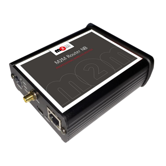
1. Starting up the Router 1.1 Accessories Unpack the router and the antenna from the product paper box. Prepare for the installation and the configuration, follow the next hints. 1.2 Cable connection 1. Mount the Narrow Band SMA-type communication antenna to the Antenna (Main) titled SMA-M interface (according to the module/router type). -
Page 6: Starting The Router
1.3 Starting the router 1. Plug the 12V DC power adapter cable to the POWER interface, then plug the adapter to the 230V electrical network. 2. The router has a pre-installed system (contains uploaded firmware and system software). After plugging the power adapter, the router begins to work, whereas its LED signals are showing the current activity during the operation. - Page 7 At first time, you have to allow the security risk in the Mozilla ® browser by choosing the Advanced Potential Security Risk option at the Then choose the Accept the Risk and Continue option here. Now, you can login to the router’s local website (LuCi interface) - through the Ethernet interface –...
-
Page 8: Accessing The Router On Ssh Connection
The login data are the following: root Username: wmrpwd Password: Then push to the Login button to load the configuration management user interface of the router. Attention! When connecting to the public network, it is recommended to change the login password! The ethernet IP address can be modified after login from the OpenWrt. - Page 9 1.6 Remote configuration of the router by Remote Device Manager ® software You can use the remote device management application (Remote Device Manager ® ) for maintaining your m2m routers. The application provides you continuous QoS monitoring of operation, remote re-configuration and installation of firmware updates.
-
Page 10: Web Administration User Interface
2. Web Administration user interface 2.1 Dashboard (Main page) After login to the web interface, the startup screen appears with the current status of the router. Build Date STM32 Firmware Check that the (OpenWrt) is 2019-07-10 or newer version, and the version –... -
Page 11: Menu
At the Network part you can identify the Modem Model, the modem identifier (IMEI), the SIM identifier (SIM ID), and the Modem RSSI (signal strength) and Modem SQ (signal quality in CREG, CSQ) and the mobile network registration, login and access information as well ( COPS You also can check the IPv4 and IPv6 WAN status and the connection Type to the public Internet. -
Page 12: System Menu
2.5 System menu You can found several system settings in these menu items: In the System menu: Hostname (router name), Time synchronisation (time and NTP server settings), Logging, Language (of user interface) Administration: Password (for admin user interface) and the SSH Access ... -
Page 13: Network Menu
You can define the remote monitoring software connection settings of the az Remote Device Manager ® (optional remote management software for firmware refresh and reconfiguartion, check QoS). Then at the Modem parameters (define special parameters for the connection). ... -
Page 14: Network Configuration Of The Router
3. Network configuration of the router 3.1 Interface settings The list of the available network interfacescan be found at the Interfaces / Interface Overview menu item. The network interfaces are listed at the Interface Overview. The interface means the eth0 USBLAN usb0 Ethernet port connection (... -
Page 15: Mobile Internet Settings (Configuring The Nb Modem)
The Stop button stops the communication on the current interface, the button reconnects the related interface connection. At the upper WAN, USBLAN, LAN title you will found further settings for the chosen Interface. 3.2 Mobile internet settings (configuring the NB modem) Open the WAN item from the upper selection. - Page 16 Setup the module for connecting to the NB-IoT mobile network (according to the assembled module type) – at the WAN interface tab. Configure the module to the wireless internet and for Narrow Band network connection (by the modem type and network behaviour) here for the WAN interface. For configuring end enabling the roaming settings –...
- Page 17 Authentication The PAP/CHAP username and PAP/CHAP password settings can be also configured here – if it is required for the connection. Click to the Save & Apply button for saving the settings, while the devices attempts then connecting to the mobile network. ONLY for NB IoT (Vodafone GDSP SIM) APN: nb.inetd.gdsp (not presented)
-
Page 18: Ethernet (Lan) Settings
Important! To be connected to a Narrow Band network can be longer than it is usual in case of 3G, 4G LTE network. NB IoT connection sometimes takes 2-3 minutes, but some other networks need more time as 5-10 minutes until the successful connection. In the overview you can be ensured about the IPv4 WAN status which will be „connected”... - Page 19 The detailed LAN interface settings can be performed by the Network Interfaces menu item at the LAN interface button. Change the default 192.168.127.1 router IPv4 address to an own IP address, regarding the current subnet. Check the IPv4 netmask to be proper for the selected and required network class which you are attempted to use.
-
Page 20: Dhcp Settings
If you are not attempted to use a fixed IP address for the router, and if you are attempted to use given IP by a different network device (by DHCP service), then modify the IPv4 address to the Static address connecting gateway –... - Page 21 Save the settings with the Save & Apply button. Further DHCP settings can be achieved at the Network menu, at the DHCP and DNS item, General Settings tab.
-
Page 22: Dns Settings
At the Active DHCP Leases part you can see the list of the devices, which given their IP addresses lease time from the router’s DHCP service (with the renewal In the Static Leases part you can devices to always provide the same dedicated IP address by the router. -
Page 23: Defining The Route Rules
At the DNS server port field you can define the port for the DNS service (by default its port number is 53). When you have modified the settings, save them by the Save & Apply button. 3.6 Defining the route rules In the Network menu, Static routes item you can define the rules for the current routing. - Page 24 On the public internet the you can have several network attack and getting unwanted communication, internet data collection by applications. These all over the unwanted network activity causes the growing the mobile network traffic and increasing the transmitted amount of data (which is unnecessarly decrease the available data package amount of the SIM card).
- Page 25 In the Status menu, Firewall item you can check the firewall statistic. The INPUT means the incoming, the OUTPUT the outgoing/transmitted and the FORWARD means the forwarded communication/traffic hereby. As it can be seen, there are several communicating IP addresses on several ports to the router and subnet.
- Page 26 At the Zones part you can a new rule to the current ones. You also can an existed rule. When you are attmepted to add a new firewall rule, it must be performed very carefully, because you can disable or tilt ports communication which are used by the router or some network services by general (e.g.
- Page 27 The firewall can be configured by default to allow or tilt the communication – according to the chosen settings. Therefore it does not protects the router against external network attacks or intrusions when just enabling the firewall feature. Further port-level filtering or interface traffic limits, or Traffic Rules settings are necessary to define! When you have modified the settings, save them by the...
-
Page 28: Port Forward Settings
3.8 Port Forward settings Here in the Network menu, at the Firewall item, Port Forwards tab you can setup, that which port forwarding rules should be valid. Here you can add the necessary ports and IP adresses. -
Page 29: Ip Routing, Nat Settings
You can add a new rule by the button. When you have modified the settings, save them by the Save & Apply button. 3.9 IP routing, NAT settings In the Network menu, Firewall item, Traffic Rules tab you can setup the Traffic Rules, and the Source NAT settings. -
Page 30: Dynamic Dns Settings
These rules must always be defined, not disallowing the general communication and must consider that the router must be further available on the network. It is easy to enclose the router from the network or disabling the remote access. Please, be careful when configure these settings. Important! Always check the used standard ports by the network services and allow these (e.g. - Page 31 When you have modified the settings, save them by the Save & Apply button.
-
Page 32: Special Settings
4. Special settings 4.1 Remote Device Manager ® settings Remote Device Manager The router parameters can be remotely reconfigured by the az ® application. It is also capable of performing remote monitoring of QoS and for installing firmware updates. Device Manager The necessary settings can be defined in the Router / Device Manager menu. -
Page 33: Monitoring The Modem
4.2 Monitoring the modem At the Router / Modem Parameters menu you can define some special operation monitoring and listener parameters for the modem. The Watchdog timeout can be declared as a modem restarting time interval trigger in case of mobile network unaccessibility. The Max. -
Page 34: Network Time Service (Ntp)
Important! Check only IP addresses, which are available to access from the current IP segment and APN zone for sure (e.g. from an enclosed APN zone the router will not access the public internet, and from the public internet it will not access the enclosed M2M APN zone). In case of M2M APN the 192.168.1.250 address can be accessed, it is possible to ping the address for checking the 3G network connection. -
Page 35: Tftp Service Settings
At the Time Servers part you can NTP time servers by its Hostname, IP-address or server name, and Port. When you have modified the settings, save by Save & Apply button. 4.5 TFTP service settings Open the Network menu, DHCP and DNS item. At the TFTP settings tab you can allow the TFTP service (Enable TFTP server), and the related further parameters. -
Page 36: Identifiying Names Connecting Machines
4.6 Identifiying names connecting machines Open the Network menu, Hostnames item. Here you can register (Add) machines or devices of your network which are using the router connection - for an easier identification. You can add logical machines names to the IP addresses which you can see as listed at the status overview. -
Page 37: Openvpn Configuration
When you have modified the settings, save them by the Save & Apply button. 4.8 VPN client (OpenVPN) configuration Open the Services menu, OpenVPN item. Here you can define and setup OpenVPN client connection and the related settings. The OpenVPN service uses the port nr. 1194. - Page 38 Attention! For using the VPN client connection service by the router, you an already existed and properly configured VPN server setting and accessibility to the VPN network. Choose a pre-defined instance (connection profile) – e.g. sample_client – then pust to the button.
- Page 39 For sake of the exact settings, we offer to read the related tunelling service description of the OpenWrt ® administration interface which you are currently using: https://wiki.openwrt.org/doc/howto/vpn.openvpn#tab__traditional_tun_server1 Save the configured settings by the Save & Apply button. 4.9 Ser2Net (RS232, RS485) configuration In case of ordering the RS232/RS485 expansion to the router, you can use the serial connection which you have to configure first.
- Page 40 The State, Timeout values are on factory default – so you don’t need to modify them it it is not necessary. The Device is also pre-defined, no need to change it! But the Options field is where you can declare connection parameters, seperated with commas or space.
- Page 41 parity second here the as EVEN, ODD, NONE stop bits then the as 1STOPBIT, 2STOPBITS data bits next is the as 7DATABITS, 8DATABITS Syntax for OPTIONS is: baudrate parity stopbit databit (or baudrate,parity,stopbit,databit) Examples: 9600 NONE 1STOPBIT 8DATABITS 19200,EVEN,1STOPBIT,7DATABITS Important! We offer to test the settings with 9600 baud speed rate first, then if it is communicating fluently with your connected device, then you can try further data speed rates.
-
Page 43: Software Refresh And Router Maintenance
5. Software refresh and router maintenance 5.1 Firmware refresh 1. Open the System menu, Backup / Flash firmware item. fwos 2. Browse the -…. compressed file then push to the Flash image button. 3. A new window will appear where the file will be checked. When it is okay, the system refreshment is possible by the Proceed button. -
Page 44: Installing Applications
4. Then the next message appears on the screen in the browser. Then the refresh method has started, while the LED2 and LED3 are continuously lighting by red. 5. Later the LED2 will be blank and only the LED3 is lighting with red. 6. -
Page 45: Restarting The Router
When it was successful, fill the name of the application you are attempted to install at the Download and install package field (e.g. MC – Midnight Commander esetében), and push to the OK button for the installation – regarding the upcoming hints on the screen. The installed packages of the router are listed lower at the Status part. -
Page 46: Shutdown / Halt Of The Router
5.4 Shutdown / halt of the router To shutdown the router device, first you have to reboot by the System / Reboot menu. When all the three LEDs blinks at once, the router is restarted and can be switched off safely as soon as you can –... - Page 47 The Restore backup is possible to reload – a previously saved configuration – when you will be able to browse and load from your computer to the router memory by pushing the button. 5.8 Handling of external storages (uSD card, USB drive) The router is able to handle the connected and mounted uSD cards, USB memory sticks.
-
Page 48: Rs485 Mbus Meter Connection
5.9 RS485 Mbus meter connection In case of using RS485 M-Bus connection we mention that the device is able to receiv 1-250 connections of MBus compatible meters. All incoming data of the connected meters will be automatically stored under the /tmp directory on the RAM drive. - Page 49 You can also use -compatible connection to the router by your computer with an SCP client (like WinSCP). You can also copy the stored files to a locally mounted uSD drive for data collection or further data logging, analysis. The incoming files of the Modbus device are stored here in CSV format by the following syntax in the CSV file: •...
- Page 50 At first time the list is empty - it is normal. Now connect the meter and switch to the Settings tab. At the bottom of the page you will find the Discovery button - Push it to discover all connected meters.
- Page 51 SFTP At the Protocol you can select the protocol. Configure the IP address of the remote (s)ftp server with FTP port number (port 21 is the default). The given IP address will be used in the file names. It is necessary to use ftp username and password at the ftp server by the targetDir (e.g. /ftp/). Note, that these must be already existing and used at the distant server side! You can declare an Id (identifier) for the concentrator connection with reading data periods (in seconds) and sending intervals (in seconds) –...
-
Page 52: Ssh Configuration
The reportid means that you can use a logical identifier to when sending CSV file to the distant server. The filenames will contain this tag and the files will be identified such easy by this ID at the server side during reception of the files and evaluation of the data. The multiheader option (values: (no) or (yes)) allows you to make header after each record... -
Page 54: Troubleshooting
6. Troubleshooting LED activity Can you see any LED activity (flashing, lights)? After 1-2 minutes inactivity of the LEDs could mean the router has a failure (configuration or firmware trouble). First you should ensure about the router is still under starting / booting phase or not. Please wait 1-2 minutes, then check the LED signals again. - Page 55 You can order a power supply from us, or buy one. Please consider the wiring and polarity, according to the previous figure of connector pinout. (Top 2-pins of the microfit plugin are wired only, the left pin is the negative.) No power? Check router that it can get any power through its microfit connector (POWER) –...
- Page 56 Checking the connection - connecting to the router through USB Download and install driver for USB connection from our website: https://www.m2mserver.com/m2m-downloads/USB_Ethernet_RNDIS_DRIVER.zip Unpack the downloaded zipped file and install the driver. After you’ve connected the USB cable you can add the driver at the Windows / Start / Control Panel / System / Device Manager. Find the Network Cards, extend it and you will found the „USB Ethernet / RNDIS Gadget”.
- Page 57 Attention! Never stops the router without requesting the reboot process, and do not remove the power socket without restarting the router before this action! Antenna Check or connect proper SMA fit antenna to the Antenna connector and mount it to the interface. The router must send and assure proper RSSI signal value and life signals.
- Page 58 SIM ERROR If you get the SIM ERROR message in the Status/Overview menu (dashboard) at the SIM ID value, then your SIM card is inactive or has malfunction. Restart the router and try again. Add valid APN settings in the Interfaces / WAN connection, Save and apply the settings and restart the router as soon as you can from the System / Reboot menu.
-
Page 59: Support Availability
7. Support availability If you have any questions concerning the use of the device, contact us at the following address: E-mail: iotsupport@wmsystems.hu Telephone: +36 20 333 1111 7.1 Contact the support line For the proper identification of the router you should use the sticker on the device, which contains important information for the call center. -
Page 60: Legal Notice
Systems LLC., with clear indication of the source. The pictures in the user guide are only for illustration purposes. WM Systems LLC. does not acknowledge or accept responsibility for any mistakes in the information contained in the user guide. change without notice The published information in this document is subject to All data contained in the user guide is for information purposes only.
Need help?
Do you have a question about the M2M Router NB and is the answer not in the manual?
Questions and answers