
Related Manuals for WM Systems M2M Industrial Router 2 SECURE


Summary of Contents for WM Systems M2M Industrial Router 2 SECURE
- Page 1 User Manual M2M Industrial Router 2 SECURE ___________________________________________________ Rev: 1.00 2023-02-09...
- Page 2 Document specifications This document was completed for the M2M Industrial Router 2 SECURE device and ® contains the hardware specification, with the most important information and software settings of the device. Document category: User Manual Document subject: M2M Industrial Router 2 SECURE ®...
-
Page 3: Table Of Contents
Table of contents CHAPTER 1. Product information ..................5 CHAPTER 2. Technical data ....................6 2.1 Power voltage / Current ratings .............................. 6 2.2 Cellular modules (order options) ............................6 CHAPTER 3. Device exterior design and appearance ............8 3.1 Safety cautions ....................................9 3.2 Mounting, fastening .................................. -
Page 4: Chapter 1. Product Information
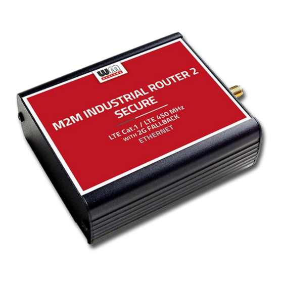
Chapter 1. Product information This secure and robust device features an Ethernet port, cellular module, and compact industrial design. It is currently available with LTE Cat.1 or LTE Cat.M/Cat.NB modules that provide enhanced coverage. This product boasts special firmware that offers additional security features as required by the ENCS, the European Network for Cyber Security. - Page 5 Security features The device uses Secure Boot system with Secure Key Storage features (on encrypted eMMC memory chip). The router continuously monitoring the operation parameters (QoS, module operation, vital signals, etc.). It has detection of network interface connections / disconnections with an alarm event sending to the Device Manager management platform.
-
Page 6: Chapter 2. Technical Data
Chapter 2. Technical data 2.1 Power voltage / Current ratings • Power Voltage / Ratings: • 12V DC, 1A power supply (9-32VDC) – powered via Microfit 4-pins power input connection (from external 12V DC power adapter) • Current / Consumption: Average: 200mA - 260mA, 12VDC (according to module version) / 2.4W –... - Page 7 Bands: o LTE Cat.M / 450MHz: 1/B2/B3/B4/B5/B8/B12/B13/B14/B18/B19/B20/B25/B26/B27/B28/ B31/B66/B72/B85 o LTE Cat.NB: B1/B2/B3/B4/B5/B8/B12/B13/B18/B19/B20/B25/B26/B28/B31/ B66/B85 o GSM/EGPRS: 850/900/1800/1900MHz...
-
Page 8: Chapter 3. Device Exterior Design And Appearance
Chapter 3. Device exterior design and appearance Industrial secure router, assembled in aluminum casing with interface connectors / ports 1 – POWER (9-32V DC): Microfit 4-pin power connector (for DC power/adapter) 2 – *SIM card slot (2FF) 3 – micro-USB connector (for configuration) 4 –... -
Page 9: Safety Cautions
Industrial secure router, assembled in aluminum casing, attachable to 35mm DIN rail(with an adapter) Safety cautions The device must be used and operated according to the user manual provided. Only a responsible and skilled person with adequate experience and knowledge in wiring and installing a router device, as instructed by the service team, should carry out the installation. - Page 10 be made without the manufacturer's permission, as this will result in the loss of product warranty. CAUTION! Only certified experts or the manufacturer are authorized to open the device enclosure. The device uses 9-32V DC power supply within the enclosure, and the enclosure should NOT be opened or the PCB touched.
-
Page 11: Mounting, Fastening
■ Look for potential hazards in your work area, such as moist floors, ungrounded power cables, frayed cords, and missing safety grounds. ■ Never work alone if hazardous conditions exist. ■ Always verify that power is disconnected from a circuit before working on it. ■... -
Page 12: Antenna
The device enclosure can be mounted using either the AB-MKL one-sided DIN-rail adapter (left) or the AB800MKL adapter (right) on a wall or DIN-rail. These accessories can be ordered - more information: https://m2mserver.com/en/product/din-rail-mount-unit-two-sided/ https://m2mserver.com/en/product/din-rail-mount-unit-one-sided/ 3.3 Antenna Please be aware that the presence of metal parts in close proximity, the metal material of the cabinet, and industrial conditions such as the use of high power levels or exposure to external radio frequency signals can cause radio... - Page 13 Microfit power cable: Type: min. 70 cm, OMYA type, 2 x 1 mm^2, halogen free, double insulated wires, min. 24 V DC voltage, wires are marked by colors and blanked. Connector type: 4-pins Microfit (2-pins are wired) Feature: provide 9..32V power supply connecting for the router (12V DC 1A).
-
Page 14: Chapter 4. Software System
Chapter 4. Software system Operation system The device runs on OpenWRT system with a micro Linux microkernel. The secure ® boot system is integrated into the hardware-level eMMC secure chip and partitions are encrypted by secure boot. The router comes with a pre-installed system, which is tailored to the customer's requirements and includes the operating system, software, and a factory default configuration. -
Page 15: Tls Protocol Communication
4.4 TLS protocol communication TLS v1.2 protocol communication can be activated between the router and the Device Manager from the software side, by choosing TLS mode or legacy communication. ® The router uses the mbedTLS library and the Device Manager uses the OpenSSL library. -
Page 16: Chapter 5. Starting The Device
Chapter 5. Starting the device 5.1 Connecting the router 1. Ensure that the router is not under power voltage, therefore the power adapter cable is removed from the POWER titled microfit connector (1) – or the adapter is not connecting to the power network. Ensure, that all the 3 LEDs (7) are blank. 2. -
Page 17: First Start
5.2 First start The router is provided with pre-installed system (which contains the operating firmware and a Linux-based command line with UCI command line interface. The router is accessible via ssh connection. 1. Connect the microfit connection power connector (1) when the router begins its operation, where the LED lights will be signing and inform you about the current status of the device. -
Page 18: Access Via Ssh Connection
5. Configure the device’s wireless internet module settings (SIM and APN) for the cellular internet connection – otherwise the router will be restarting in ever 10 minutes. 6. The module registration to the cellular network is signed by the LED3 flashing after the settings. - Page 19 Accept the security risk (RSA token) encryption key usage warning notice (visible at first time only). Login information ■ Username: root ■ Password: wmrpwd At the Linux command line you can use standard Uc Linux kernel 5.10 compatible commands and execute scripts on the device. You can also use UCI command line interface commands here.
-
Page 20: Chapter 6. Important Notes
Chapter 6. Important notes • For security reasons, we do recommend to change the password immediately for accessing the administration user interface. • The parameters that can be used for the APN settings are always provided by the SIM card issuer (mobile service provider). Contact them for APN, SIM PIN, PAP/CHAP username username, PAP/CHAP password and other information. -
Page 21: Chapter 7. Troubleshooting
Chapter 7. Troubleshooting LED activity Can you see any LED activity (flashing, lighting)? After ca. 2 minutes inactivity of the LEDs could mean the router has a failure (configuration or firmware trouble). First you should ensure about the router is still under starting / booting phase or not. Please wait 2-3 minutes, then check the LED signals again. - Page 22 In case of failure, check the power supply connection at the socket plug side and on the microfit connector at the router side. The top 2-pins of the microfit plugin are wired only, the left pin is the negative. Check the next figure for the pinout and check the 12V DC voltage on the microfit connector (by a multimeter) of the power adapter that it provides 12V or not.
- Page 23 Establish a USB connection between the PC and the router with a micro-USB cable connected to the socket marked USB. (The driver must be installed on the PC according to the Installation Guide). Set the IP address of the USB-Ethernet interface on the PC for the “USB Ethernet / RNDIS Gadget”...
- Page 24 Note, that the router will not powered off immediately, due to it have supercapacitor components inside. Therefore, the router will getting enough spare power (ca. for up to 10 seconds) to close every connection, interfaces and ports and shutdown the device safely.
- Page 25 SIM card cannot be detected Turn off the router - unplug the power plug from the POWER connector of the device. Then, make sure that there is a SIM card in the SIM slot with the chip facing up and the bevelled corner facing inward, and then push the card in until it stops.
-
Page 26: Chapter 8. Support Availability
Chapter 8. Support availability If you have any questions concerning the use of the device, contact us at the following address: E-mail: support@wmsystems.hu Phone: +36 20 333 1111 8.1 Contact the support line For the proper identification of the router you should use the sticker on the device, which contains important information for the call center. -
Page 27: Chapter 9. Legal Notice
WM Systems LLC., with clear indication of the source. The pictures in the user guide are only for illustration purposes. WM Systems LLC. does not acknowledge or accept responsibility for any mistakes in the information contained in the user guide.
Need help?
Do you have a question about the M2M Industrial Router 2 SECURE and is the answer not in the manual?
Questions and answers