WM Systems M2M PRO4 User Manual
Hide thumbs
Also See for M2M PRO4:
- Installation manual (34 pages) ,
- User manual (73 pages) ,
- Installation manual (34 pages)

Related Manuals for WM Systems M2M PRO4


Summary of Contents for WM Systems M2M PRO4
- Page 1 M2M Router PRO4 ® User Manual OpenWrt ® user interface settings v1.70 _________________________________________ 2021-04-13...
- Page 2 ® configuration possibilities for the proper operation of the device. Document category: User Manual Document subject: M2M Router PRO4 ® Author: WM Systems LLC Document version No.: REV 1.70 Number of pages: Linux Kernel: 4.14.23 OpenWRT software version: 202011161 Document status:...
-
Page 3: Table Of Contents
Table of contents 1. DEVICE CONFIGURATION (OPENWRT USER INTERFACE) ......5 1.1 Web user interface ......................5 1.2 Dashboard (Main page) ..................... 7 1.3 Menu overview ........................8 1.4 System menu ........................9 1.5 Router menu........................10 1.6 Services menu ........................10 1.7 Network menu ........................ - Page 4 5. MAINTENANCE ................... 48 5.1 Firmware Flashing ......................48 5.2 Restarting the router ......................50 5.3 Backup of router settings ....................51 5.4 Restore of router settings ....................53 5.5 Clone configuration ......................53 6. ADMINISTRATION ..................55 6.1 Password change ......................55 6.2 Logging ..........................
-
Page 5: Device Configuration (Openwrt User Interface)
Device configuration (OpenWrt user interface) 1.1 Web user interface Important! The device’s software contains a pre-configured system. Please check the configuration, and if the settings are not match with your expectations, change the configuration settings and save them. 1. The router’s local web user interface (LuCi ®... - Page 6 4. Then click on the Accept the Risk and Continue button to access the router’s webpage. 5. The OpenWRT ® system’s LuCi ® web interface has loaded into your browser. Now fill the Username and Password fields and click on the Login button for the entry. root wmrpwdM2M Username:...
-
Page 7: Dashboard (Main Page)
1.2 Dashboard (Main page) After you have logged in the web interface, a startup screen appears with all relevant information and the current status of the router. At the System part, you can check the installed software build (M2M Software model and M2M 202011161 Software version) where it should be or newer. - Page 8 The Uptime shows the spent time interval since the last bootup (or reboot). At the Network part, first you can check the wireless module availability at IPv4 WAN Status or IPv6 WAN Status part, as the module’s IMEI identifier and the SIM ID identifier of the used SIM card.
-
Page 9: Menu Overview
1.3 Menu overview By the menu you can access the following features: Status – Status data, operation Logs (system, kernel, event log), monitoring the operation (at Processes and Realtime graphs) System – System settings and administration, software installation (3rd party tools), Device Manager settings, startup settings, Scheduled tasks, Mount points (uSD card storage and Flash file system content), LED configuration, Firmware flashing, Backup/Restore of the configuration settings, Custom commands, Reboot of the system) -
Page 10: System Menu
1.5 System menu • You will found several system settings in the System and the Administration menu items. • Installation of further Software (3rd party tools, applications for the Linux distribution). • Device Manager (remote management server settings) • You can define the Startup applicatons •... -
Page 11: Network Menu
1.7 Users menu • You can add (define) or modify, delete Users for allowing to access the system • Clone config backup/restore) plain text • Clone config backup/restore plane text (the sam in format) • Define periodic ping for QoS and network health check •... -
Page 12: Statistics Menu
• The Firewall rules can be declared here as the following submenu items: Port forward, IP route, NAT settings. • Also you can configure the RS485 port communication settings at the Serial Proxy menu. • IPSEC (tunneling settings for secure connections) •... -
Page 13: Important Notes
2. Important notes • By security reasons, we do recommend to change the web user inteface login and password as soon as you can. • The 4G LTE modules can be used by inserting SIM card into the SIM1 tray •... - Page 14 • We offer to measure your throughput data and network traffic (by minutes, hours) – use the Status / Realtime Graphs or Statistics / Graphs and calculate the estimable data transmitting amount according your expectations and the data limits of the used SIM card.
-
Page 15: Interface Settings
3. Network configuration 3.1 Interface settings The list of the available network interfaces can be found at the Network / Interfaces menu item. usb0 USBLAN interface is assigning the microUSB connection ( interface). interface is assigning the Ethernet port connections (LAN1, LAN2, LAN3, LAN4 physical br-lan interfaces, which are bridged to the logical interface - at Linux side). -
Page 16: Cellular Internet Settings
3.2 Cellular internet settings The wireless module / cellular network settings of the router can be configured at the Network Edit menu, Interfaces menu item. Open the item from the interface list by the button. The wireless connection can be operated through the dynamic and static IP address (IPv4) assignment also - which is provided by your mobile operator. - Page 17 The Service type is the used wireless settings – you can choose a LTE (4G) communication band or you can leave it on the default value: / UMTS (3G) /GPRS (2G) Auto mode – which means This mode grants the best speed and quality option on the network and fallback feature (the highest cellular network service is not available - e.g.
- Page 18 Public Internet APN APN name: net Attention! ALWAYS use the given APN name and password of your Mobile Operator. ONLY for NB IoT (Vodafone GDSP SIM) APN: nb.inetd.gdsp (not presented) APN password: ONLY for GDSP SIM (WM2M GDSP) By using the GDSP SIM you have to follow the hints of the mobile operator when filling the SIM #1 APN, APN username and password fields.
- Page 19 The PAP/CHAP username and PAP/CHAP password settings can be also configured here – if it is required for the connection. For configuring and enabling the roaming settings – in case of international or country border usage – you may need to setup the Mobile country code and Mobile network code parameters –...
-
Page 20: Usb Settings (Usblan Interface)
3.3 USB settings (USBLAN interface) The router has an alternative LAN interface through the USB connection. The usage of this port is ideal for configuration purposes, while you can use active data communication throught your LAN interfaces. USBLAN interface settings for the USB Ethernet connection, which can be performed by Network / Interfaces menu item at the... -
Page 21: Ethernet (Lan) Settings
(Static address DHCP client Here you can define Protocol ) for getting IP address from a connected network device (another local router device or similar network host). static You can define the IPv4 address of you connection. The IPv6 addresses can be also used, but by default the setting for the router is disabled by the disabled IPv6 assignment length ( ). - Page 22 Save your settings by the Save & Apply button. Then the bridged BR-LAN interface IP address will be changed according your request due to the new settings. disabled The IPv6 addresses can be also used. By default it is by the IPv6 assignment length (if Enable you want to use, it).
-
Page 23: Dhcp And Dns
DHCP You can find further important settings at the DHCP and DNS menu. At the General Settings tab tab you can define IP range (Start, Limit) and IPv4 netmask for your network. 3.5 DHCP and DNS settings The DHCP service allows the automatic IP address providing for the connecting devices in the current IP segment by the router. - Page 24 Disable DHCP for this interface If you attempted to enable the DHCP service, uncheck the option. Then the related parameter settings will be visible with their default settings. The Start field means the starting IP addres in the subnet for the connecting devces (by default 192.168.x…).
- Page 25 Define a Hostname and the valid MAC-Address of the device and the required IPv4-Address. When you have modified the settings, save them by the Save & Apply button.
-
Page 26: Defining The Route Rules (Static Route)
3.6 Defining the route rules (Static route) We offer to check the currently used route rules - ARP routes, and the IPv4 and IPv6 route rules which you can find in the Status / Routes menu. Here you can define a new IP route rule, by the button. - Page 27 We highly recommend to check the firewall settings and configure the communication to reject the unnecessary boundaries. On the public Internet, you can have several network attack and getting unwanted communication, internet data collection by applications. These all over the unwanted network activity causes the growing the mobile network traffic and increasing the transmitted amount of data (which is unnecessarly decrease the available data package amount of the SIM card in the router).
- Page 28 If you’ll find and identify communication from an unwanted IP/port address/range, then you can disable or limit the affected port or IP-segment at the firewall setting rules to deny/prohibit this traffic by disabling the communication on it. In the Status menu, Firewall menu item you can check the actual firewall statistic. INPUT chain OUTPUT chain means the incoming, the...
- Page 29 As it can be seen, there are several communicating IP addresses on several ports for the router and subnet. Another method for limitation is to disable all ports, to open and enable only the necessary and used communication ports, define the used IP address range by allowing exact IPs. You can modify the firewall settings at the Network menu, at the Firewall item, General Settings...
- Page 30 You can Delete the settings or modify. Below, at Zones part you can a new rule to the current ones. You also can an existed rule. Save the modified settings by Save & Apply button. Under the Advanced Settings tab, you can restrict outbound, inbound, or forward traffic to individual subnets.
- Page 31 (by default) or they are necessary to existing for some network services or could required by some other running tasks). E.g. Port nr. 67 is used by DHCP service, as Port nr. 80 for web service, DNS for port nr. 53, OpenVPN at port nr. 1194 and the RS485 also uses a dedicated port). You can add a new port (which you have configured for the relevant service) to the firewall rules by the button.
-
Page 32: Port Forward Settings
If you have changed something, save the settings with the Save & Apply button. The firewall enables or disables all communications by default, depending on the settings. Therefore, enabling the firewall service does not in itself provide protection, additional ports level filtering or other restrictions on interface traffic! For a port-level filtering or interface traffic limits or Traffic Rules... -
Page 33: Nat Settings
When you modified the settings, save them by the Save & Apply button. If you already have a forwarding rule, you can Enable/Disable, or Edit, Sort or Delete the rule. 3.9 NAT settings In the Network menu, Firewall item, Traffic Rules tab you can setup the Traffic Rules, and the Source NAT settings. - Page 34 The Source NAT settings (below) can be performed for each protocol (tcp, udp), that the router allows the redirection of data –which incoming IP address and port must be redirected to which outgoing IP address and port and must be forwarded the data traffic. You also can define a port range, hereby.
-
Page 35: Advanced Services
4. Advanced services 4.1 Network diagnostics Open the Network menu, Diagnostics item. Here you can check the availability of an IP address, that is it accessible (push button), is there a naming service provided, and is there response between two IPs (push button), furthermore you can query the path of the communication (by button). -
Page 36: Tftp Settings
You can further NTP servers or some. You can also specify the addresses of the NTP servers (NTP server candidates). The most of the NTP time servers are using the port nr. 123 (UDP) for time synchronisation. Note that the router must have public internet access for reaching the time servers or the time server must be in the same APN zone. - Page 37 Enable TFTP server, and define the further related parameters to make the FTP service operating for sending files to a remote or distant IP address (e.g. to a server). The FTP service can be useful for forwarding the data of connected devices and meters via ftp to a server, remote IP address.
-
Page 38: Identifiying And Connecting Computers
When you have modified the settings, save them by the Save & Apply button. 4.4 Identifiying of connecting computers Open the Services menu, Hostnames item. Here you can register those machines, network devices which are using the router’s connection - for an easier identification. - Page 39 The local hostname for the router (which name will appear for external devices on the network), it can be changed at the System / System menu item, where you will find the General Settings tab, at the Hostname field you can define a unique device name – to make it easy to identify the device on the network.
- Page 40 9600 19200 The Baudrate (default is bps, or you can use bps as standard for RS485). At the IEC-1107 baud field, you can choose the IEC-meter compatible handle (data speed rate will be used according to the meter). Databits / Parity / Configure the Mode value which can be (which means in sequence: Stopbits...
- Page 41 4.6 M-Bus meter connection The device is able to receive max. 30 connected MBus compatible meters. The data speed rate is configured for 2400 bps / 300 bps. Check the Services menu, Mbus menu, Settings tab, you can define the Mbus data connection parameters.
- Page 42 This shown example is a basic configuration, but we can provide different fields and configuration options at MBus settings – according the Customer requirements. (If you have unique request, specify and send us). At the arealetter parameter you can add a logical name for the identification connection. Define the dcunumber for identifing the concentrator device.
- Page 43 The location of the received data The data will be requested and incoming data of the connected M-Bus devices will be automatically stored in the temporary storage pool (/tmp) of the RAM drive. Then you can ftp the data to a remote IP address (by sftp, tftp, ftp client or server). Make a connection to upload the stored files to your distant server IP address before data loss –...
-
Page 44: Voice Call Config
MeterList part you can see the registered and discovered MBus compatible utility meters. You can Add the connected M-Bus meters by configuring the meter parameters. Save the configured settings by the Save & Apply button. 4.7 Voice Call Config At the Network / Voice Call Config menu item it is possible to setup commands you are attempting remote control commands. -
Page 45: Led Configuration
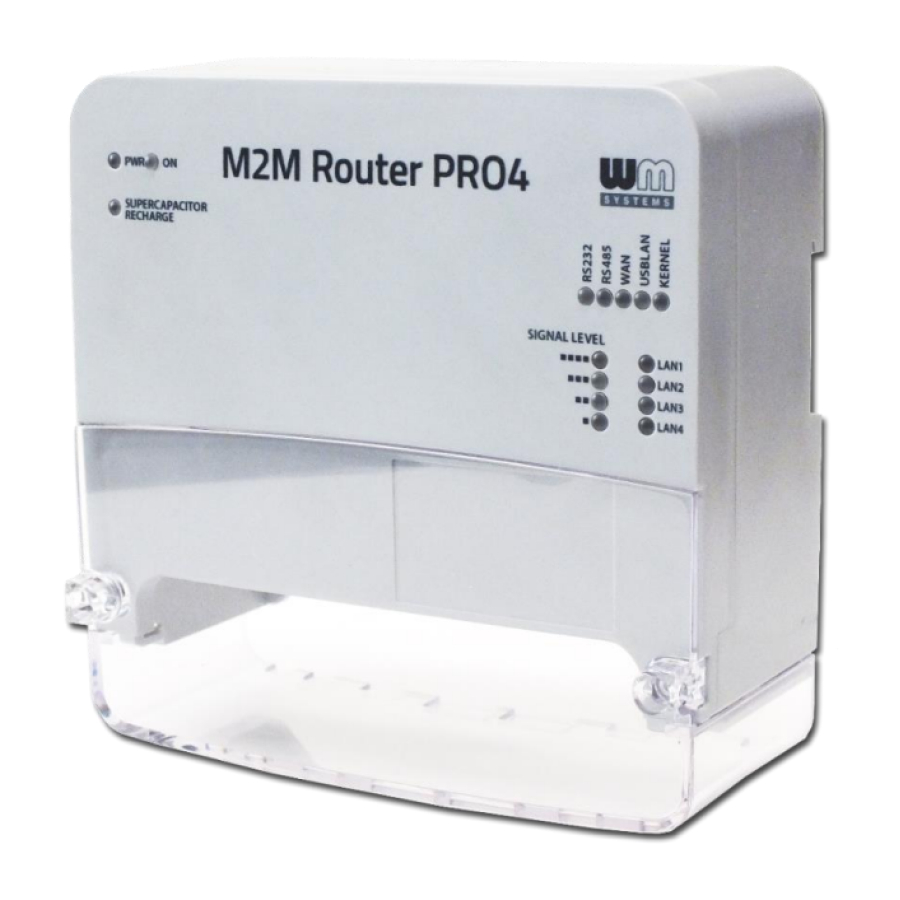
When you modified the settings, save them by the Save & Apply button. 4.8 LED configuration The router has 16 LEDs to assign the current operation and connection status of the device. The POWER INDICATION leds and SIGNAL STRENGTH leds are fixed, but the further 9 LEDs are reconfigurable (CONNECTIVITY leds and LAN1..LAN4 leds) in the web user interface. - Page 46 Here you find the webadmin settings of the LED settings of the router. You can a LED to define or a LED setting from the list. netdev The Trigger allows to choose an event type of operation. E.g. means the network interface connection type, and Device identifies the related network interface.
- Page 47 First you can see the Phone Book where you can define or phone numbers. Then you have to Enable the selected phone number. At the SMS commands part you can choose preset commands by selecting them for the number. In the case of an SMS from a preset phone number, the router runs the preset command (s) assigned to the phone number: e.g.
-
Page 48: Maintenance
5. Maintenance 5.1 Firmware Flashing 1. Download the latest firmware from our website for the router - by using the following URL in your web browser: https://www.m2mserver.com/en/product/m2m-router-pro4/ Choose the Downloads tab at the middle on the router’s website, then look at the Firmware part. - Page 49 5. After the compressed firmware file upload to the router, a new window will appear where the uploaded file is checked. Then you can start the system software refresh by the Proceed button. 6. Then another message appears on the screen in the browser, that he refresh method has been started.
- Page 50 7. When beginning the firmware installation, the router’s LED lights will check the installation progress. During the whole installation KERNEL LED is continously ligthing until the finish. When the installation begins, the USBLAN LED is flashing then later ligthing by green. MBUS RS485 USBLAN...
- Page 51 Then the router will be restarted, where its LED lights will assign. After 40-50 seconds it will be available again and accessible on its default address. You can login again to the web user interface. 5.3 Backup device settings The router settings are automatically stored by the OpenWrt ®...
- Page 52 Note that the device stores only its own settings and components! If you have instakked 3rd party applications or using your own scripts, the system WILL NOT BACKUP these and these are not part of the compressed backup file! You must save all the additional files, scripts and directories manually by your own.
- Page 53 At the Actions tab, you can Create default configuration feature allows you to save the current configuration as a last known good configuration for saving by the button. Then the device will backup the configuration to the router. A popup window will appear, where you have to push OK.
-
Page 54: Clone Configuration
By the Restore backup option you can restore a previously saved system configuration archive – which was saved to your computer –to the router and apply. Push the Browse button at Restore backup part and choose the previously saved archive file (tar.gz extension compressed file) from your computer and then push the button. - Page 55 This is especially useful if you save the configured configuration to your computer and want to load it to multiple routers (as a basic configuration) - making the settings easier. What can be uploaded to other devices with the button after browsing.
-
Page 56: Administration
6. Administration 6.1 Password change Open the System / Administration menu. At the Router Password part you can fill the Password and and confirm it the at the Confirmation field. IMPORTANT NOTES • The password must contain min. 8 characters, lowercase and uppercase letters and numbers or special characters are allowed. -
Page 57: Logging
6.2 Logging Open the System / System menu find the Logging tab. There you can define a log file (Write system log file) and the level of logging (Log output level). You also are able to limit the log file size (System log buffer size), and you can define an External system log server (IP address) and its port, protocol for sending the log files for a distant IP address. -
Page 58: Language Settings
hh:mm:ss ) values if you would like to filter the listing.) Sure, it’s not obligatory to define the whole datetime format, you can use just years and month or else. 6.3 Language settings Open the System / System menu find the Language and Style tab. -
Page 59: User Management
6.4 User management The device can handle multiply user accounts for accessing the system or the web and limit the permissions, defining roles. This makes the router able to providing a multi-user capable environment, which is supporting the workgroups, to execute tasks for the users (e.g. administrator role, installer, maintanence group, riport maker roles, etc.). - Page 60 Define User Name and select a User Group for the permission / entry-level. Menu enabling Then choose the required items by the related checkboxes to provide the required menus for the role of the user account. Then, the selectable sub-menus will be appearing, where you can grant a more detailed permission for the menu items by selecting the sub-items.
- Page 61 Important! The password must contain min. 8 characters, lowercase and uppercase letters and numbers or special characters are allowed. It is obligatory to use passwords by using minimum 3 special characters (upper case, numbers or special characters (e.g. numbers)). Note, that the current Password cannot be seen here due to some security rules – the characters shown as are empty here.
-
Page 62: Installing 3Rd Party Applications
If you want to use periodic ping as checking an IP address or remote server, device as checking its availability by the device if you want to use this service by accessing from the Services menu / Periodic Ping item. Save the configured settings by the Save &... - Page 63 The installed packages are listed at the Installed tab by its Version. To download the software catalog, first you have to push to the button, when the configured opkg list will be downloaded from the repository with the list of the available applications.
-
Page 64: Mount Points
Then the list of the application with the name will be listed. Choose the package you want and choose the installation option. After the installation of the selected package, now you can use the installed Linux application / component which you were chosen. Now you can use the installed Linux application / component which you were installed. - Page 65 Mount Swap There at the Global Settings part, you can configure the areas. The Mounted file systems are listed the connected and mounted devices (such as uSD card, connected USB pendrives, hard disks, USB and internal Flash). These file systems will be attached /mnt under the directory in SSH.
- Page 66 Here you can the settings of a device (media) or a device from the list. You can also new mount points here. /dev/sda1 To add an inserted uSD card choose the button and choose the Device ( /dev/mmcblk0p1 for uSD card) and push to the Save &...
-
Page 67: Statistics
6.8 Statistics 6.8.1 View the statistics reports In the Statistics menu / Graphs menu item, you can see the current and archive statistic graphs of the router’s perfomance. - Page 68 Choose a tab (Processor, Interface, System Load, Memory) to check the stored QoS /resource statistics. 6.8.2 Configuring statistics reports In the Statistics menu / Setup menu item, you can configure the current statistic settings for collecting and evaluating router’s performance data and the performance graph settings. The main screen is the Collectd Settings, where you can define the Data collection interval and the Linux-side settings.
- Page 69 wwan0 Then allow the Enable this plugin and enable the inteface too. To performing the change of the new settings, you have push to the Save & Apply button. The changes will be active in the next statistic cycle interval. Then wait a couple of minutes and go to the Statistics menu / Graphs item and check the wwan0 Interfaces...
-
Page 70: Remote Access (Ssh)
Here you can configure a list of custom commands as a startup script to your device (running a script or load a resident program). When you have modified the settings, save them by the Save & Apply button. 6.10 Remote access (SSH) You can access the device remotely according the current network and firewall settings. -
Page 71: Uci Usage From Command Line
Accept (Yes) Putty other terminal’s Security Alert of the RSA2 key of the router to allow and trust the connection – by security reasons. SSH login data: root wmrpwdM2M Login: Password: Now you are logged in, at the OpenWrt ® ’s command line. - Page 72 6.12 IPSec You can configure IPSec for tunneling at the Network / IPSEC menu item. Listen on interface Here at the IPSEC part, you can setup the option by the button. Choose one or more interface, which you want to configure the IPSEC service. At IKEv1 Phase1/Phase2 settings you can define and a logical name for Encryption algorithm and Hash algorithm, Diffie-Hellmann group settings for the tunnel.
- Page 73 Then at Tunnel settings part you can define and a logical name for Local Subnet and Remote Subnet of the subnets – add the IP segment addressess please to the fields. The IKEv1 Phase 2 name is a free to choose logical name for the tunnel connection, where the Key exchange method can be selected for the tunnel.
- Page 74 main agressive The IKEv1 connection mode can be Add keys to the Local gateway identifier and Remote gateway identifier fields. When you have modified the settings, save them by the Save & Apply button. Important! The used IPSEC method in the IPSEC menu has a Strongswan based operation. You can read more about the Strongswan and the useful parameters in the OpenWrt website here: https://openwrt.org/docs/guide-user/services/vpn/ipsec/strongswan/start The IPSEC can be also configured from UCI (command line).
-
Page 75: Openvpn Settings
6.13 OpenVPN settings You can configure VPN tunnel at the Services menu, OpenVPN menu item. The service uses the default nr. 1194 port during its operation. Here you will found three pre-configured instances for operating VPN connections. For activating a rule (setting), you have to Enable the instance, and then it. - Page 76 tcp. At proto field choose a protocol – as The client option needs to be checked if you want to use the VPN as VPN client. The remote field is here for configuring the remote server IP address (for client). When you have modified the settings, save them by the SSave &...
-
Page 77: Device Manager Settings
#uci show openvpn Then the current arguments of the OpenVPN settings will be listed to the CLI: To setup a listed parameter you have use the following syntax and to commit the changes to apply. #uci set openvpn.sample_server.dev=’tun’ #uci commit 6.14 Device Manager settings The application is available through license pack constructions, please advise our sales about the license pack options. - Page 78 This is continuously provides operation parameters and status (as health of network access, signal strength, QoS, etc.). Beyond monitoring features, it can be used as well maintenance reconfiguration of devices. You can also change the firmware of the device. You can manage one or even thousands of router devices...
-
Page 79: Pin Code Change
For the configuration of the Device Manager ® open the Router / Device Manager menu item. Configure the DM Port Number – by default it is the nr. 4443. The DM Name is the name of the serverad a unique identifier, where DM User Name is the server account and the DM IP Address (server IP) is also necessary for the connection. -
Page 80: Troubleshooting
7. Troubleshooting LED signals / LED activity For understanding the LED activities, please check the Chapter 1.5 and Chapter 6.6. Power supply Connect the AC power supply according the hints of the following figure. Then the router must be powered on, and the PWR (Power) and ON LEDs must be lighting and the device has been started, the boot process begins. - Page 81 RS485 connection You can make utility meter connection to the modem by connecting RS485 cables to upper 3-pins of the industrial terminal block connector. You also need to configure and enable the operation by the Network / Serial Proxy menu. When data traffic is performed through the cable, the RS485 LED will be blinking during the communication (Rx and Tx) –...
- Page 82 • Not enough RSSI value – means: connect a proper 4G antenna to the ANTENA mount or use a better gained antenna to the device for the better RSSI value (signal strength). • Check NW registration – means: APN and SIM registration is in progress •...
- Page 83 For accessing the router’s web user interface we offer the Mozilla Firefox web browser only. Try to access the router on its USB interface by your browser: https://192.168.10.1 Ensure that the router uses a SIM card and it’s APN is already confifured and the WAN, SIGNAL LEVEL leds are active or not.
-
Page 84: Hardware Additions & Settings
8. Hardware additions & settings 8.1 Supporting mini-PCIe modules By default the router contains an embedded 4G LTE module on the mainboard. There is other order option for using LTE450 or LTE Cat.M/Cat.NB module by the internal miniPCIe interface. There the following wireless modules are supported: •... -
Page 85: Support
9. Support 9.1 Technical Support If you have any questions concerning the usage of the device, contact us at the following contact: E-mail: iotsupport@wmsystems.hu Phone: +36 20 3331111 Online product support can be required here at our website: https://www.m2mserver.com/en/support/ For the proper identification of your device, use the device’s glued sticker and its information, which contains important information for the call center. -
Page 86: Legal Notice
WM Systems LLC., with clear indication of the source. The pictures in the user guide are only for illustration purposes. WM Systems LLC. does not acknowledge or accept responsibility for any mistakes in the information contained in the user guide.
Need help?
Do you have a question about the M2M PRO4 and is the answer not in the manual?
Questions and answers