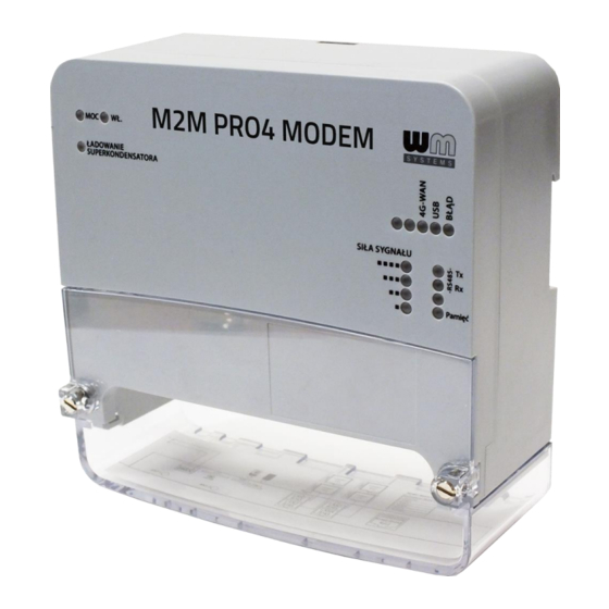
WM Systems M2M PRO4 MODEM User Manual
Hide thumbs
Also See for M2M PRO4 MODEM:
- Installation manual (34 pages) ,
- User manual (86 pages) ,
- Installation manual (34 pages)

Related Manuals for WM Systems M2M PRO4 MODEM


Summary of Contents for WM Systems M2M PRO4 MODEM
- Page 1 M2M PRO4 MODEM ® User Manual v0.92 _________________________________________ 2020-02-18...
- Page 2 Document specifications This document was made for the M2M PRO4 MODEM ® device and it contains the detailed description of the configuration possibilities for the proper operation of the device. Document category: User Manual Document subject: M2M PRO4 MODEM ®...
-
Page 3: Table Of Contents
Table of contents 1. DEVICE CONFIGURATION (OPENWRT USER INTERFACE) ......5 1.1 Web user interface ......................5 1.2 Dashboard (Main page) ..................... 7 1.3 Menu overview ........................8 1.4 Status menu ........................9 1.5 System menu ........................9 1.6 Services menu ........................10 1.7 Users menu ........................ - Page 4 5. MAINTENANCE ................... 46 5.1 Firmware Flashing ......................46 5.2 Restarting the device ......................48 5.3 Backup of device settings ....................49 5.4 Restore of device settings ....................51 5.5 Clone config backup/restore ....................52 6. ADMINISTRATION ..................54 6.1 Password change ......................54 6.2 Logging ..........................
-
Page 5: Device Configuration (Openwrt User Interface)
Device configuration (OpenWrt user interface) 1.1 Web user interface Important! The modem software contains a pre-configured system. Please check the configuration, and if the settings are not match with your expectations, change the configuration settings and save them. 1. The modem’s local web user interface (LuCi ®... - Page 6 4. Then click on the Accept the Risk and Continue button to access the modem’s webpage. 5. The OpenWRT ® system’s LuCi ® web interface has loaded into your browser. Now fill the Username and Password fields and click on the Login button for the entry. root Username: wmrpwdM2M...
-
Page 7: Dashboard (Main Page)
1.2 Dashboard (Main page) After you have logged to the web interface, a startup screen appears with all relevant information and the current status of the device. At the System part, you can check the installed software build (M2M Software version) where 202002071 it should be or newer. -
Page 8: Menu Overview
At the Network part, first you can check the wireless modem availability at IPv4 WAN Status or IPv6 WAN Status part, as the module’s IMEI identifier and the SIM ID identifier of the used SIM card. The wireless network access’ current status and health, properties can be checked at Modem RSSI (cellular network signal strength), Network Name, Network Code and Cell ID is getting from the mobile operator. -
Page 9: Status Menu
Status – Status data, operation Logs (system, kernel, event log), Firewall, monitoring the operation (at Processes and Realtime graphs) System – System settings and administration, software installation (3rd party tools), startup settings and scheduled tasks, time synch, mount points (for Flash memory, file systems), LED configuration, Firmware flashing, Backup/Restore of the configuration settings, Custom commands, Reboot of the system) Services –... -
Page 10: Users Menu
The Mount Points are showing the available (mounted) shares of the Linux file system and flash memory. The LED Configuration is also configurable for custom needs. You also can Backup and restore your system configuration, applying Flash firmware updates. -
Page 11: Network Menu
1.7 Network menu Here you can configure the settings of each network Interfaces (for the wireless module and the USB port) You can define the DHCP and DNS settings for the wireless LTE module and connection. Define Hostname for the modem for easier identification of the device on your network. ... -
Page 12: Logout Menu
1.9 Logout menu This menu item will allow you to log out from the OpenWrt ® environment in your computer browser. -
Page 13: Important Notes
2. Important notes By security reasons, we do recommend to change the web user inteface login and password as soon as you can. The IPv6 protocol is disabled for the LAN interfaces by default, change it if you want to use it instead of the IPv4 protocol. - Page 14 network. When the 4G network will be available again, the device will switch back to the 4G network. This feature is configurable for the WAN interface of the device. If you need, you can choose dedicated wireless service type or automatic mode (using which is accessible).
-
Page 15: Network Configuration
3. Network configuration 3.1 Interface settings The list of the available network interfaces can be found at the Network / Interfaces menu item. The USB-LAN interface is listed for configuring and using the modem by your PC through the micro usb0 USB connection ( interface). - Page 16 The wireless connection can be operated through the dynamic and static IP address (IPv4) assignment also - which is provided by your mobile operator. At the General Setup tab, you can see the current status of the interface with transmitted data amount.
- Page 17 If you have to use a dedicated network like 3G, 2G, etc., then choose the required network type. Take consider, that the fallback mode will be inactive in this mode – if you choose the and it the network will be not available, there will not be provided 3G or 2G fallback (if the choosen network is not available, the device won’t get mobile network access).
- Page 18 The device is already connected to the cellular network, it has active data traffic and the RX (received data), TX (transmitted data) at Packets and KB (KBytes) values are growing. At the Advanced Settings tab you will found further settings for the wireless module. By default we do not offer to change these settings, only if you are special requirements at operating the mobile network communication by the modem (these are the LCP Echo settings, the Bring up on boot and the use built-in IPv6 management parameters mainly).
- Page 19 usb0 The USBLAN ( ) interface settings for the PC connection can be performed by using the Network / Interfaces menu item at the USBLAN part, where you need to choose the button. Then choose the General Setup tab. (Static address DHCP client Here you can define Protocol ) for getting IP address from a...
-
Page 20: Dhcp And Dns Settings
3.4 DHCP and DNS The DHCP and DNS settings can be achieved at Network menu, DHCP and DNS item at General Settings. Below, at the Active DHCP Leases part you can see the list of the devices, which given their IP lease time addresses from the modem’s DHCP service (with the renewal At the Static Leases you can add network devices by the... -
Page 21: Defining Route Rules (Static Routes)
When you have modified the settings, save them by the Save & Apply button. 3.5 Defining route rules (Static route) We offer to check the currently used route rules - ARP routes, and the IPv4 and IPv6 route rules which you can find in the Status / Routes menu. Here you can define a new IP route rule, by the button. -
Page 22: Firewall Settings
3.6 Firewall settings By default, the firewall service is active, but it allows all communication. It can be necessary to limit the traffic. Important! We offer to check the network traffic on your modem. Check connections and active communication channels (port number, incoming IP) and listen the incoming activities and the output traffic! We highly recommend to check the firewall settings and configure the communication to reject the unnecessary boundaries. - Page 23 In the Status menu, Firewall menu item you can check the actual firewall statistic. INPUT chain OUTPUT chain means the incoming, the is the outgoing/transmitted and the FORWARD chain means the forwarded communication/traffic hereby. You can also see the Rejected chain here below.
- Page 24 As it can be seen, there are several communicating IP addresses on several ports for the device and subnet. Another method for limitation is to disable all ports, to open and enable only the necessary and used communication ports, define the used IP address range by allowing exact IPs. You can modify the firewall settings at the Network menu, at the Firewall item, General Settings tab.
- Page 25 Accept/Deny/Reject As you can see, the communication rules are listed here by their acceptance ( br-lan with the directions of the communication ( or other). Here, you can check or modify these firewall rules for the communication, at the Input (incoming), Output (outgoing) and Forward operations one by one by accept it, or reject, drop.
- Page 26 some other running tasks). E.g. Port nr. 67 is used by DHCP service and the DNS which is also using a dedicated port (nr. 53). Therefore you can add new port (which you have configured for the relevant service) to the firewall rules by the button.
- Page 27 For the port-level filtering or interface traffic limits or Traffic Rules settings are also necessary to define! Here you can Enable / Disable or a configured rule. When you have modified the settings, save them by the Save & Apply button.
-
Page 28: Port Forward Settings
3.7 Port Forward settings Here in the Network menu, at the Firewall item, Port Forwards tab you can setup the port forwarding rules for the modem. You can add a new rule by the button. Here you can define a rule with the necessary Protocols, interface (External zone and Internal zone), Ports (External ports, Internal ports) and the Internal IP address values. -
Page 29: Nat Settings
3.8 NAT settings In the Network menu, Firewall item, Traffic Rules tab you can setup the Traffic Rules, and the Source NAT settings. You can add a new rule by the button and Save & Apply to close the upcoming window. Here you can open ports (e.g. - Page 30 The proper port filtering, routes are minimizing the communication, what could be important by safety reasons, and could decrease the open threads and risks of some safety leaks. Always limit the access of services, and decrease the amount of the throughput communication on the network by these rules to provide the operation only for the necessary services, ports, ip addresses.
-
Page 31: Advanced Services
4. Advanced services 4.1 Ping IP address / checking IP Open the Network menu, Diagnostics item. Here you can check the availability of an IP address, that is it accessible (push button), is there a naming service provided, and is there response between two IPs (push button), furthermore you can query the path of the communication (by button). -
Page 32: Network Time Service (Ntp)
4.2 Network Time Service (NTP) Important! This NTP time synchronisation is highly important for data storage of the incoming readout results (metering files) on the modem’s memory. Because the device uses file syntax with the current datetime values. The supercapacitor provides max. 2 days of keeping the date-time values, but the NTP sync is also very important to keep updated time for the device and your data. - Page 33 At the Time Servers part you can NTP time servers by its Hostname, IP-address or server name, and Port. You can a Time server entry. The most NTP time servers are using the UDP Port nr. 123 for time synchronisation. You can find a NTP time servers on the Internet.
-
Page 34: Identifiying And Connecting Computers
4.3 Identifiying of connecting computers Open the Services menu, Hostnames item. Here you can register those machines, network devices which are using the modem’s connection - for an easier identification. You can logical names to the IP addresses of the connecting machines, which you can see as listed at the Status / Overview menu as external connected clients. - Page 35 4.4 Serial Proxy (RS485 settings) Important! The utility meters can be connected to the modem via RS485 port, where they can send data to the modem (activity is signed by RS485 RX LED) and the modem can also exchange data with the meters (RS485 TX led signs it).
-
Page 36: Rs485 Meter Connection
There you will find the Name RS485 and the Port, which must be configured. Choose the right value for the Protocol here: : no dataflow : full duplexity rawlp: one-direction communication telnet: for further usage We offer to use the option here, because the meters are sending raw text format files to the modem. -
Page 37: The Incoming Utility Meter Files
4.6 The incoming utility meter files All incoming data of the connected meters will be automatically stored under the /tmp directory on the RAM drive. Important! Note that, this is a temporary storage pool, where all stored data of the directory will be deleted after rebooting. -
Page 38: Iec Scheduler
The modem will be automatically transmit further the incoming data at the scheduled time intervals to the configured IP address of a server. Therefore, we suggest to configure the client and make the server-modem connection to upload the stored files from the modem to the distant server IP address, in case of unwanted data loss – regarding the next setting options. - Page 39 It is necessary to use FTP username and FTP password according to the current ftp server’s settings which you already made. The Connection retries it is configurable to setup the number of tryings in case of uploading problem or cellular network or inaccessibility of the remote FTP server. The Sending frequency value means the scheduled interval of the utility meter file sending, where Week Month...
-
Page 40: Configuration Of The Utility Meters
Examples: Week first In case of the schedule setting, the meter(s) will be requested to readout at the day of every week. value means a daily once readout The Remote Directory is the target directory location on the remote FTP server. Add the proper path of the file storage, please. - Page 41 monthly in case of a readout, the day of event will be the day of the month – which is not configurable. HHMM Furthermore, you can define an exact Read Time (in format ), where the scheduled readout time (hour and minutes) can be configured exactly. The Registers can be also configured to be read out –...
-
Page 42: Tr-069 Settings
4.8 TR-069 settings Open the Network menu, TR-069 menu item for configuring the remote management server (ACS) connection settings. At the ACS Login part you can define the server access. At the ACS URL you need to define the http https or secured protocol address (URL) of the remote management server. - Page 43 STUN (Simple Traversal of UDP There you also able to define the optional STUN Login settings. through NATs (Network Address Translation)) server is an implementation of the STUN protocol, which enables the STUN functionality for the TR069 settings. Here you can find mode information about STUN: https://www.voip-info.org/vovidaorg-stun-server/ On the web interface, you can Enable the service, define its Address, Port number, User name and Password for its proper operation.
-
Page 44: Led Configuration
Easycwmp Note that the TR-069 can be also configured by the ® daemon, which is also installed to the system and can be started by the ® command EasyCwmp Command Line Reference „UCI Command Line Check our „ ® ” documentation and ®... - Page 45 LED: lg33 Green LED LED: lg31 Green LED (cellular signal RS485 RX (permanent) strength: ) (data receive) LED: lg23 Green LED LED: lg22 Green LED (cellular signal (permanent) strength: ) (not used, configurable) LED: lg13 Green LED LED: lg11 Green LED (cellular signal POMIEC (permanent)
-
Page 47: Maintenance
5. Maintenance 5.1 Firmware Flashing 1. Download the latest device firmware from our website by using the following URL in your web browser: https://www.m2mserver.com/m2m-downloads/fwos-BE008x_Pro4_PGE-Modem.202001223.zip 2. Choose the Downloads tab at the middle on the website of the device, then look at the Firmware part. - Page 48 6. After the compressed firmware file upload to the modem, a new window will appear where the uploaded file is checked. Then you can start the system software refresh by the Proceed button. 7. Then another message appears on the screen in the browser, that he refresh method has been started.
-
Page 49: Restarting The Device
first empty titled 11. Then as sigining the progress of installation, the LEDs will also flashing by green. 4G-WAN BLAD 12. When the installation has been completed, the BLAD LED will be blank, but all further progress leds in the line will be green, which signs that the installation has been over and the device is already rebooted. -
Page 50: Backup Of Device Settings
5.3 Backup device settings The modem settings are automatically stored by the OpenWrt ® system, but there can be other situations when you need to restore the settings to a previously saved settings. You can save these settings to your computer or restore back to the modem anytime by following the next hints. - Page 51 are not part of the compressed backup file! You must save the additional files, scripts and directories manually by your own. You can include or exclude your files and directories in your backup process by using the Configuration tab here. You can edit the list with all necessary directories you need. Of course, you need to know the modem device’s file system to make it right.
-
Page 52: Restore Of Device Settings
At the Actions tab, you can Create default configuration feature allows you to save the current configuration as a last known good configuration for saving by the button. Then the device will backup the configuration to the device. A popup window will appear, where you have to push OK. 5.4 Restore device settings You can Restore default configuration –... -
Page 53: Clone Config Backup/Restore
default configuration factory configuration You can also restore the or the of the device manually by the Reset button on the modem device - without using the OpenWrt ® web interface. For more Installation Guide information, please check the , Service Features part. 5.5 Clone config backup/restore The device current configuration settings can saved (backup) and strored into plain text format by the Users menu, Clone config backup / restore plane text menu item. - Page 54 To backup your system settings into a plain text file, push the button. A pop-up message will apear to save the archive file to your computer. Save the file, please. This is very helpful to move the saved configuration file to your computer and then later restore these settings to a different modem device by the Browsing…...
-
Page 55: Administration
6. Administration 6.1 Password change Open the System / Administration menu. At the Password part you can fill the Password and and confirm it the at the Confirmation field. IMPORTANT NOTES The password must contain min. 8 characters, lowercase and uppercase letters and numbers or special characters are allowed. -
Page 56: Logging
6.2 Logging Open the System / System menu find the Logging tab. There you can define a log file (Write system log file) and the level of logging (Log output level). You also are able to limit the log file size (System log buffer size), and you can define an External system log server (IP address) and its port, protocol for sending the log files for a distant IP address. -
Page 57: Language Settings
hh:mm:ss ) values if you would like to filter the listing.) Sure, it’s not obligatory to define the whole datetime format, you can use just years and month or else. The main important event are logged as the reboot time, FTP connection success/failure, FTP file upload OK or wrong. -
Page 58: User Management
Here you can choose a pre-defined Language for the web user interface by selecting an item from the list. Auto preference means that the OpenWrt ® UI language will be configured according to your browser language settings. Push to the Save &... - Page 59 Certainly, only the configured menu items and permissions will be valid for the configured user account. You can also grant by enabling access permission to the account. When you have finished, push to the Save & Apply button for saving the new account settings. Now, as you can see, the new user account is listed.
- Page 60 Then, after you will Logout from the system, the new user can Login with his account and able to access the declared menu items, features by his pre-defined role. wmrpwdM2M Note that the default password for all manually added users is the following: User After, you have will login by the new user login there will be a new menu item, the Options,...
- Page 61 At the Day value, you can define how many days of period will be applied to the modem reboot. E.g. Day=2 means reboot on every second day at the Hour/Minute defined time. If you want to use periodic ping as checking an IP address or remote server, device as checking its availability by the device if you want to use this service by accessing from the Services menu / Periodic Ping item.
-
Page 62: Installing 3Rd Party Applications
6.6 Installing 3rd party applications Open the System menu / Software menu item, find the Actions tab. Important! This feature is available only, when the public Internet is accessable by the SIM card and the used APN. Enter the name of the application, which you are attempted to install to the Download and Midnight Commander install package field (e.g. -
Page 63: Mount Points (Flash Memory)
Now you can use the installed Linux application / component which you were installed. Open SSH terminal window to configure your new application or use it. E.g. about our example, enter Midnight Commander the „mc” to start the tool which you were installed from the repository. 6.7 Mount points (Flash memory) The device is handling the connected and mounted file systems of the internal Flash and further partitions. -
Page 64: Statistics
6.8 Statistics 6.8.1 View the statistics reports In the Statistics menu / Graphs menu item, you can see the current and archive statistic graphs of the modem’s perfomance. Choose a tab (Processor, Interface, System Load, Memory) to check the stored QoS /resource statistics. - Page 65 6.8.2 Configuring statistics reports In the Statistics menu / Setup menu item, you can configure the current statistic settings for collecting and evaluating modem’s performance data and the performance graph settings. The main screen is the Collectd Settings, where you can define the Data collection interval and the Linux-side settings.
- Page 66 There are further tabs in the upper sub menu as General Plugins, Network Plugins, Output plugins where you can enable the collected performance items, interfaces, etc. For example, to the wireless network statistics settings, let’s choose the Network tab, and there Wireless tab below.
- Page 67 6.9 Custom commands You can configure and initiate custom Linux commands on the rotuer at the System menu, Custom Commands menu item. By the button you can define a Description for the Command and the Custom arguments (user can define the further parameters and arguments) and the Public access to any user.
-
Page 68: Using The Uci Command Line Interface
Accept (Yes) the Putty or other SSH terminal’s Security Alert of the RSA2 key of the device to allow and trust the connection – by security reasons. SSH login data: root Login: wmrpwdM2M Password: Now you are logged in, at the OpenWrt ®... -
Page 69: Troubleshooting
7. Troubleshooting LED signals / LED activity For understanding the LED activities, please check the Chapter 1.5 and Chapter 6.6. Power supply Connect a ~100-240V AC power supply according the hints of the following figure. Then the modem must be powered on, and the MOC (Power) and WL (ON) LEDs must be lighting and the device has been started, the boot process begins. - Page 70 You also need to configure and enable the operation by the Serial Proxy menu and the IEC scheduler settings (FTP, meter settings) menu. When data traffic is performed through the cable, the RS485 Tx or the RS485 Rx LEDs will be blinking during the communication –...
- Page 71 Power outage – disconnecting the ports and data connection In case of power/electricity network outage or maintain, the wireless and RS485 meter data connection and session will be established if it was interrupted throug a way and it was later estabilished, reconnected.
-
Page 72: Support
8. Support If you have any questions concerning the usage of the device, contact us at the following contact: E-mail: iotsupport@wmsystems.hu Phone: +36 20 3331111 Online product support can be required here at our website: https://www.m2mserver.com/en/support/ For the proper identification of your device, use device’s glued sticker and its information, which contains important information for the call center. -
Page 73: Legal Notice
WM Systems LLC., with clear indication of the source. The pictures in the user guide are only for illustration purposes. WM Systems LLC. does not confirm or accept responsibility for any mistakes in the information contained in the user guide.
Need help?
Do you have a question about the M2M PRO4 MODEM and is the answer not in the manual?
Questions and answers