
Related Manuals for WM Systems Industrial Router M2M


Summary of Contents for WM Systems Industrial Router M2M
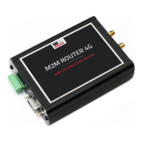
- Page 1 M2M Industrial Router ® M2M Industrial MBUS Router ® User Manual v2.40 ____________________________________________________ 2022-12-06...
- Page 2 In case of CDMA450 device, the CDMA-specific MSIN settings are listed in this document. Document category: User Manual Document subject: M2M Industrial Router ® Author: WM Systems LLC Document version No.: REV 2.40 Number of pages: Hardware Identifier No.: BE0077F OpenWRT build version: 202209191 Linux Kernel version: 4.9.184...
-
Page 3: Table Of Contents
Table of contents CHAPTER 1. Starting the Router .................... 5 1.1 Product variants ....................................5 1.2 Interface connectors ..................................5 1.3 Safety cautions..................................... 7 1.4 Mounting, fastening ..................................9 1.5 Antenna ........................................10 1.6 Further accessories................................... 10 1.7 Connecting the router ..................................12 1.8 First start ........................................ - Page 4 5.9 UCI usage from the command line ............................58 5.10 IPSEC settings ....................................58 5.11 VPN client (OpenVPN) configuration ..........................60 5.12 Periodic ping and Periodic reboot settings ........................65 5.13 Voice call settings.................................... 66 5.14 Run commands remotely (SMS config settings) ...................... 67 CHAPTER 6.
-
Page 5: Chapter 1. Starting The Router
Chapter 1. Starting the Router 1.1. Product variants The router can be ordered with LTE Cat.1 or LTE Cat.M / Cat.NB cellular module with 2G/3G fallback feature. The industrial router contains an RS485 port (transparent or Modbus communication - terminal block connection, 3pins) by default. As an option, further por texpansions can be ordered for the router as: •... - Page 6 1 – POWER (9-32V DC): Microfit connector power connector (for 12V DC adapter) 2 – SIM card slot (2FF) – in case of CDMA450 version, not presented 3 – micro-SD slot 4 – micro-USB connector (for configuration) 5 – Reset button hole 6 –...
-
Page 7: Safety Cautions
MB+|MB-| A | B |GND Industrial router with Modbus / RS485 connector (left side, terminal block, 5- pins) and an RS232 (right side, DSUB-9 connector) expansion 1.3 Safety cautions The device must be used and operated according to the related user manual. The installation can be carrying out only by a responsible, instructed and skilled person by the service team, who has enough experience and knowledge about carrying out the wiring and installing a router device. - Page 8 By general the device is using 9-32V DC mains inside the enclosure! DO NOT OPEN THE ENCLOSURE and DO NOT TOUCH THE PCB. Router current and consumption • Power voltage: 9..32 VDC • Current: 160-260mA, 12V DC (depending on cellular module version) •...
-
Page 9: Mounting, Fastening
■ Look carefully for possible hazards in your work area, such as moist floors, ungrounded power extension cables, frayed power cords, and missing safety grounds. ■ Do not work alone if hazardous conditions exist. ■ Never assume that power is disconnected from a circuit. Always check. ■... -
Page 10: Antenna
The device enclosure can be fixed by the AB-MKL (left) one-sided DIN-rail adapter, or by the AB800MKL adapter (right) to a wall or DIN-rail (accessories can be ordered) More information: https://m2mserver.com/en/product/din-rail-mount-unit-two-sided/ https://m2mserver.com/en/product/din-rail-mount-unit-one-sided/ 1.5 Antenna Please note that close metal parts, the cabinet metal material and the industrial conditions as the usage of high rate power or other external gained radio frequency signals can cause radio signal disturbance and could cause weak... -
Page 11: Further Accessories
1.6 Further accessories The following accessories are not part of the product, these are order options. Microfit power cable: Type: min. 70 cm, OMYA type, 2 x 1 mm^2, halogen free, double insulated wires, min. 24 V DC voltage, wires are marked by colors and blanked. -
Page 12: Connecting The Router
RS485 cable: Type: 70 cm OMYA type, 3 x 0,75 mm^2, halogen-free, double insulated wire pair, up to min. 24V DC breakdown voltage, colour signed cabling, blanked on the cable end – for supporting the 24V DC power voltage. Type: terminal block, 3 pins Function: RS485 connection for external devices Cabling must be done considering the next pinout (from left to right): GND, A, B. -
Page 13: First Start
3. Insert an activated SIM card to the SIM slot (2) - the SIM chip surface must be look to top and the cutted edge of the SIM must be look to the router – then push the SIM until it will be fixed and closed (you will hear a soft click sound). (In case of necessary of SIM removal you have to power off the router and push the SIM a bit, while it will be released and can be removed). - Page 14 1. Connect the microfit connection power connector (1) when the router begins its operation, where the LED lights will be signing and inform you about the current status of the device. 9-32V DC power voltage input (interface nr. 1) should be used by the DC powering with the microfit connection 12V DC power adapter, or you can use alternatively 9-32V DC power voltage with own cabling (follow the pinout hints).
-
Page 15: Web User Interface Of The Router
Attention! • We suggest to change the login password on the web interface. • If it is necessary, enable the DHCP service. • Enable the firewall rules and IP route rules for the Ethernet connecting devices. • Check the RS485 settings (Ser2net). 7. - Page 16 Then the router’s local web interface will be loaded and you can login. • Username: root • Password: wmrpwd Push to the Login button. Attention! Don’t forget to change the login password before connecting the router to the public cellular network!
-
Page 17: Access Via Ssh Connection
1.10 Access via SSH connection The router can be accessed through ssh connection also, when it is available on its IP address – use the putty terminal utility/tool for the connection 1. Connect to the 192.168.10.1:22 IP address. (Login: root, Password: wmrpwd) 2. - Page 18 To review the UCI commands and options that can be used, we recommend to read UCI Reference Guide, which can be downloaded from our website. https://www.m2mserver.com/m2m-downloads/UCI_Command_Line_Reference_v3.pdf E.g. you can make a query to ask the current setting of a service (openvpn, ser2net, ddns, etc.
-
Page 19: Chapter 2. Web Administration User Interface
Chapter 2. Web Administration user interface 2.1 Dashboard (Main page) After login to the web interface, the startup screen appears with the current status of the router. At the System part you can check that the Build Date. It should be 202209191 or newer version. -
Page 20: Menu
The Local Time shows the currently received time, the Uptime shows the spent time since the last reboot/start. At the Modem part you can identify the CREG field you will find the cellular network code and cell identifier. At the COPS field the cellular network name. Modem RSSI (dBm value) and Modem SQ (CSQ value) show the values of the mobile network reception field strength. -
Page 21: Status Menu
Services – Dynamic DNS settings, OpenVPN settings, Ser2Net (RS485 settings) Network – network interface settings, DHCP, DNS, hostname, IP route rules (static routes), diagnostics, Firewall, voice call config, SMS config 2.3 Status menu • In the Status you can check the current status (Overview), •... -
Page 22: System Menu
If you give a new MSIN number, then the WAN interface will be automatically configured for the router. This setting can be checked at the Network/Interfaces menu. You can store the router settings with the Save button. The Save & Apply button stores the settings and reconfigure the router related on these settings. -
Page 23: Router Menu
• Installation of further Software (3rd party tools, applications) from the online software repository • You can setup Startup applicatons and services during the operation (start/stop them) • You also can define Scheduled Tasks for starting them in the right time and sequence •... -
Page 24: Network Menu
• In the Ser2net menu you can configure RS485 operation settings 2.8 Network menu • Here you can configure the settings of each network Interfaces. • You can modify the DHCP and DNS settings. • Define network device name for the router at the Hostnames. •... -
Page 25: Chapter 3. Important Notes
Chapter 3. Important notes • For security reasons, we do recommend to change the password immediately for accessing the administration user interface (local webpage). Read Chapter 6.6 for detailed settings. • Some protocols are disabled by default on the router, but most of them you can enable to use: o The DHCP service is turned off by default. - Page 26 We do recommend to disable all ports and protocols in the Firewall that you are not currently using (connection / channel / data transfer) taking into account access to the required ports and channels. To check this, the Status / Firewall menu section is an excellent option for scanning through traffic and the Network / Firewall menu, where you can add new rules or modify existing ones.
- Page 27 menu, remove the interface with the Delete button. From then on, the router will not be restarted even if no SIM card is inserted. • HTTP, HTTPS redirect and HTTPS certifications and SSL certifications are used.
-
Page 28: Chapter 4. Network Configuration Of The Router
Chapter 4. Network configuration of the router 4.1 Interface settings The list of the available network interfacescan be found at the Interfaces / Interface Overview menu item. The network interfaces are listed at the Interface Overview. interface means (eth0) the Ethernet port connection, the USBLAN is the USB- Ethernet (usb0) and the... -
Page 29: Cellular / Mobile Internet Settings
4.2 Cellular / mobile internet settings Open the item from the upper selection. Then at the General Setup tab you can see the current status of the interface and the transmitted data amount. Setup the module for connecting to the CDMA 450 / 2G / 3G / LTE or Cat.M / Cat.NB cellular network (according to the assembled module type) –... - Page 30 Attention! In case of CDMA450 router version you don’t need to configure these settings. Wireless network field – we offer to use the No Change option or use the 4G/3G/2G option (automatic detection mode with 3G/2G „fallback” option). For further „fallback” modes, choose 4G/2G or 4G/3G modes.
- Page 31 Attention! The available APN settings will be provided by the SIM card provider mobile operator or your mobile internet service provider. The available international settings and roaming services are provided also by the M.O.s. Attention! LTE450, LTE Cat.M and Cat.NB (Narrow Band) networks require a compatible SIM card! Ask your network operator / service provider for a useful 2FF type SIM card.
-
Page 32: Ethernet (Lan) Settings
You can find more network settings on the Advanced Settings tab if you want to set more. 4.3 Ethernet (LAN) settings For the interface, at the LAN menu item at the General Setup tab you can define an own IP range (IPv4 address), with the related IPv4 netmask (subnet mask). - Page 33 The detailed LAN interface settings can be performed by the Network Interfaces menu item at the LAN interface button. We recommend that you change the router's default 192.168.127.1 address (IPv4 address) to a custom IP address, depending on your subnet - or the way you want it to be served by the router device.
-
Page 34: Dhcp Settings
4.4 DHCP, DNS settings The DHCP service allows the automatic IP address providing for the connecting devices in the current IP segment by the router. The DHCP settings can be found at the Network / Interfaces menu (according to the required interface). To enable DHCP service, uncheck “Ignore interface”. - Page 35 The further DHCP settings can be achieved at the Network menu, at the DHCP and DNS item, General Settings tab. At the Active DHCP Leases part you can see the list of the devices, which given their IP addresses from the router’s DHCP service (with the renewal lease time). In the Static Leases part you can devices to always provide the same dedicated IP address by the router.
-
Page 36: Dns Settings
This can be required by adding values to the Hostname, the MAC-Address and the IPv4-Address. When you have modified the settings, save them by the Save & Apply button. 4.5 DNS settings You can configure the DNS service from the Network / DHCP and DNS menu, with chossing the Advanced Settings tab. -
Page 37: Defining The Route Rules
At the DNS server port field you can define the port for the DNS service (by default its port number is 53). When you have modified the settings, save them by the Save & Apply button. 4.6 Defining the route rules In the Network / Static routes menu you can define the rules for the current routing. -
Page 38: Firewall Settings
4.7 Firewall settings By default, the firewall is active, but it allows all communication by default. It is necessary to limit the traffic. On public internet a device can suffer from several network attacks and getting unwanted traffic, data collection. These unwanted network activities causing the grow of the mobile network traffic and increasing the transmitted data amount (which is unnecessarly decrease the available data capacity of the SIM card). - Page 39 If will you identify communication from an unwanted IP/port, then you have to disable or limit the occured port or IP-segment at the firewall setting rules to deny this traffic. In the Status / Firewall menu you can check the firewall statistic. The INPUT means the incoming, the OUTPUT the outgoing/transmitted and the FORWARD means the forwarded communication/traffic hereby.
- Page 40 You can modify firewall settings at Network / Firewall menu, General Settings tab. For first, the communication rules are listed here with the directions and operation of the communication rules. Here, you can see and modify the general rules of the communication, at the Input (incoming), Output (outgoing) and Forward operations one by one by accept it, or reject, drop.
- Page 41 At the Advanced Settings tab you can limit the incoming, outgoing, and forwarded traffic for each subnets. When you have modified the settings, save them by the Save & Apply button. The firewall can be configured by default to allow or tilt the communication – according to the chosen settings.
-
Page 42: Port Forward Settings
4.8 Port Forward settings Here in the Network / Firewall menu, Port Forwards tab you can setup, that which port forwarding rules should be valid. Here you can add the necessary ports and IP adresses. -
Page 43: Ip Routing, Nat Settings
You can define the necessary port and IP address. Or you can add a new rule by the button. When you have modified the settings, save them by thev Save & Apply button. 4.9 IP routing, NAT settings In the Network menu, Firewall item, Traffic Rules tab you can setup the Traffic Rules, and the Source NAT settings. - Page 44 You can add a new rule by the button. When you have modified the settings, save them by the Save & Apply button. Here you can open ports (e.g. for TCP) for the packages, or you can define new forwarding rule settings for the interfaces (New forward rule). Always set the rules carefully so as not to exclude the possibility of basic communication, and you should also make sure that the router remains available on the network, because it is easy to exclude ourselves or just the possibility of remote login.
-
Page 45: Dynamic Dns Settings
4.10 Dynamic DNS settings First you have to start the Dynamic DNS service. Open the Systems / Startup menu to enable the feature. Roll down to the „ddns” feature and push to the button to initialize the service. Then wait until the service list will be refreshed and the „ddns” will be listed as an service. - Page 46 There push to the button. After the restart, you have to log in again and configure the „ddns” service. For that, in the Services / Dynamic DNS menu you can allow the DDNS service providing and the IP address of the DDNS. New settings can be by the button or the current can be changed by the button –...
-
Page 47: Chapter 5. Special Settings
Chapter 5. Special settings 5.1 Device Manager ® settings Our Device Manager application can be used for the remote management of the ® router, which is used for the remote maintenance and reconfiguration of the router in addition to the continuous monitoring of the operating characteristics (network access, field strength, runtime, QoS). -
Page 48: Ping An Ip Address
IMPORTANT! These must be also configured in the Device Manager and the router must access the IP address of the Device Manager server (where the application is executing remotely). You can check that it is accessed by performing a ping. 5.2 Ping an IP address Open the Network / Diagnostics menu. -
Page 49: Network Time Service (Ntp)
5.3 Network Time Service (NTP) Open the System / System menu, Time Synchronisation part. You can add hereby the refresh interval at the Update interval (in seconds). Here, you can setup the timezone can enable or disable the NTP client function (when receiving time data) and provide NTP time to connected devices (Provide NTP server). -
Page 50: Tftp Settings
You can assign the selected hostnames to the IP address with the button, then if connected, the clients will appear in the Status / Overview menu item on the main page with this name. If you have modified the settings, save by Save &... -
Page 51: Rs485 Settings (Ser2Net)
5.6 RS485 settings (Ser2net) First you have to start the „ser2net” service. Open the Systems / Startup menu to enable the feature. Roll down to the „ser2net” feature and push to the button to initialize the service. - Page 52 Then wait until the service list will be refreshed and the „ser2net” will be listed as an service. Then push to the button of the line of the „ser2net” service to start the feature. Then restart the device from the System / Reboot menu.
- Page 53 There push to the button. After the restart, you have to log in again and configure the „ser2net” service. To configure the RS485 port, open the Services / Ser2net menu. Here you can define the properties of the incoming transparent data transmission. At the Proxies section, enable the RS485 option to activate the communication.
- Page 54 For the Timeout value, you can specify the amount of timeout (in seconds) – default value is 30 seconds, 0 value means transparent transmitting without delay. Do not change the value of the Device field!
- Page 55 Options: A complex parameter with Baudrate selection + Stopbit definition + Databits definition + Parity type Baudrate (default is 9600 bps for the RS485) can be defined between 300 bps and 115 200 bps. Stopbit value can be 1 or 2 Databits value can be 7 or 8 Parity value can be EVEN, ODD or NONE Examples:...
-
Page 56: Led Configuration
5.7 LED configuration Open the System / LED Configuration menu. Here you can specify the rules for the LEDs for each LED status. Use Name to add a name for a rule. Under the LED Name you can select which LED status you want to set: •... -
Page 57: Remote Access (Ssh)
You can a new one, or a LED setting. When you have modified the settings, save them by the Save & Apply button. 5.8 Remote access (SSH) The device can be accessed remotely, including its settings - which you can change remotely. -
Page 58: Uci Usage From The Command Line
Here you can use micro uCLinux kernel 4.9 compatible commands or execute scripts. The router's operating system uses the embedded Micro uClinux kernel version 4.9 and interprets UCI Command line interface commands - see. For downloadable commands, see the downloadable guide for more information. 5.9 UCI usage from the command line The UCI (Unified Configuration Interface) is an OpenWrt... - Page 59 Roll down to the „ipsec” feature and push to the button to initialize the service. Then wait until the service list will be refreshed and the IPsec will be listed as an service. Then push to the button of the line of the IPSec service to start the feature.
-
Page 60: Vpn Client (Openvpn) Configuration
Then restart the device from the System / Reboot menu. There push to the button. After the restart, you have to log in again and configure the strongSwan IPsec. You can configure the service through ssh connection, from command line. Read the OpenWrt website for more information on possible IPSec settings: https://openwrt.org/docs/guide-user/services/vpn/ipsec/strongswan/start 5.11 VPN client (OpenVPN) configuration... - Page 61 Then push to the button of the line of the „opevpn” service to start the feature. Then restart the device from the System / Reboot menu. There push to the button.
- Page 62 After the restart, you have to log in again and configure the „openvpn” service. For that, open the Services / OpenVPN menu, where you can set up an OpenVPN connection. The OpenVPN service default port nr. is 1194. You will find three pre-configured VPN connections that you can enable or change your settings.
- Page 63 So, choose any profile from the ones listed - e.g. the sample_client profile - that is, the VPN client, then press the button to edit. The following window will appear, where you can set the following: Configure at least the next fields on this page: proto (Protocol): here define the connection type –e.g.
- Page 64 Then return to the OpenVPN menu, where you can enable the given setting with the Enable option, then press the button to start the configured VPN connection, then press the Save & Apply button again to save the status of the services. For the proper settings, we offer to read the related tunelling service description of the OpenWrt administration interface which you are currently using:...
-
Page 65: Periodic Ping And Periodic Reboot Settings
For this, the current OpenVPN settings are displayed on the command line: Set according to the following syntax and then comment: #uci set openvpn.sample_server.dev=’tun’ #uci commit 5.12 Periodic ping and Periodic reboot settings For matching the industrial standard requirements, you can define an time interval for periodic daily restart of the router if you want in the Router / Periodic Reboot menu. -
Page 66: Voice Call Settings
If you want to use periodic ping as checking an IP address or remote server, device as checking its availability by the router if you want to use this service by accessing from the Router / Periodic Ping menu. Save the configured settings by the Save &... -
Page 67: Run Commands Remotely (Sms Config Settings)
You can also use the button to add additional phone numbers and select the reboot command for the phone numbers. Press the Save & Apply button to save the settings. 5.14 Run commands remotely (SMS config settings) You can execute commands on the router remotely when an SMS message was sent to the router’s SIM phone number. - Page 68 number and the elapsed time since the last boot info to the phone where the SMS has been sent). When you have changed something, press the Save & Apply button to save the settings.
-
Page 69: Chapter 6. Software Refresh And Router Maintenance
Chapter 6. Software refresh and router maintenance 6.1 Firmware refresh 1. Open the System menu, Backup / Flash firmware item. 2. At the bottom part, browse the fwos-…. compressed file at the Image Browse button, then push to the button. 3. -
Page 70: Installing Applications
5. Then the next message appears on the screen in the browser. Then the refresh method has started, while the LED3 is continuously lighting by and sometimes the LED2 is flashing. 6. At the end of the installation - the LEDs will no longer flash - the system will reboot 2x, then the OpenWrt system will start and load as described. - Page 71 First you have to push the button and setup the software distribution configuration in the popup windows, where you have to define the path of the installation packages are stored. Then the settings by the button. Afterall, push to the button to refrest the available software catalog - from the software repository.
-
Page 72: Restarting The Router
Important! This feature is available when the public internet can be accessed by the SIM card, APN zone. When it has been successful, then add the name of the application you are attempted to install at the Download and install package field (e.g. „MC” in case of Midnight Commander), and push to the OK button for the installation –... -
Page 73: Shutdown / Halt Of The Router
6.4 Shutdown / halt of the router To shutdown the router device, first you have to reboot by the System / Reboot menu. When all the three LEDs blinks at once, the router is restarted and can be switched off safely as soon as you can –... -
Page 74: Backup And Restore Of Settings
When you enter the password, the web interface replaces the entered characters with asterix (*). At least 6 characters must be entered for the password. Press the Save button to save the new password. 6.7 Backup and restore of settings The router settings are automatically saved by the OpenWrt system. - Page 75 Important! During subsequent restarts, the router will always start with these saved settings - as the default configuration. The router only saves its own settings and services! If you have manually installed additional programs or are using your own scripts, it is IMPORTANT to know that they will NOT be saved! You need to ensure that non-standard applications, scripts, directories are backed up manually.
- Page 76 If you want to request a full system restore, save the archive (full) backup file previously saved to your computer - .tar.gz. format - you can download it back to your device. To do this, you can validate your request here in the System - in the Backup / Flash Firmware menu, in the Restore backup field.
-
Page 77: Clone Configuration
To reset the router configuration: You can do it here in the OpenWrt interface, by also pressing the button in the web interface menu item. Or you can use the Reset button on the router to reset the router to factory defaults - see. - Page 78 If the service has status, then you can start the service by pushing the button to initialize the service. To stop the service, push to the button. If the service has been listed as , then push to this button and wait for the refresh of the list.
-
Page 79: Log
There push to the button. After the restart, you have to log in to the system and you can use the configured service. 6.10 Log Open the System / System menu, check the Logging tab. Here you can define a system log file (Write system log file) - where a directory structure, path and file name must be specified - and also set the log output level. - Page 80 You can limit the size of the log file (System log buffer size) and set the IP address of the External log server (IP address), port, protocol - to send the log files to a remote server. Press the Save & Apply button to complete the settings.
-
Page 81: Chapter 7. Troubleshooting
Chapter 7. Troubleshooting LED activity Can you see any LED activity (flashin, light)? After ca. 2 minutes inactivity of the LEDs could mean the router has a failure (configuration or firmware trouble). First you should ensure about the router is still under starting / booting phase or not. Please wait 2-3 minutes, then check the LED signals again. - Page 82 In case of failure, check the power supply connection at the socket plug side and on the microfit connector at the router side. The top 2-pins of the microfit plugin are wired only, the left pin is the negative. Check the next figure for the pinout and check the 12V DC voltage on the microfit connector (by a multimeter) of the power adapter that it provides 12V or not.
- Page 83 Establish a USB connection between the PC and the router with a micro-USB cable connected to the socket marked USB. (The driver must be installed on the PC according to the Installation Guide). Set the IP address of the USB-Ethernet interface on the PC for the “USB Ethernet / RNDIS Gadget”...
- Page 84 Antenna Use the proper antenna type regarding the used cellular module and mobile network. Connect the SMA antenna properly to the antenna connector by mounting to the antenna interface. In case of presence of two antenna connectors, the left antenna is the MAIN, the secondary is the DIVERSITY.
- Page 85 SIM/APN failure It means a SIM or APN failure, if the LED2 will not light for minutes. If the device is not registering to the network, then the modem was not initiated properly, and the router will restart itself after 10 minutes. This could caused by a not proper APN setting –...
- Page 86 mobile service provider that the SIM card is active and ready to use data packet (IP communication). Restart the router by reconnecting the power connector. RSSI and CSQ values (signal strength of the cellular network) If you will receive 99 RSSI and CSQ signal value continuously, that means you have to use another antenna or move the antenna to another position, whil you will get appropriate signal values at reception.
-
Page 87: Chapter 8. Support Availability
Chapter 8. Support availability If you have any questions concerning the use of the device, contact us at the following address: E-mail: support@wmsystems.hu Telephone: +36 20 333 1111 8.1 Contact the support line For the proper identification of the router you should use the sticker on the device, which contains important information for the call center. -
Page 88: Chapter 9. Legal Notice
WM Systems LLC., with clear indication of the source. The pictures in the user guide are only for illustration purposes. WM Systems LLC. does not acknowledge or accept responsibility for any mistakes in the information contained in the user guide.
Need help?
Do you have a question about the Industrial Router M2M and is the answer not in the manual?
Questions and answers