Table of Contents
Advertisement
Quick Links
Advertisement
Table of Contents

Related Manuals for Parker FTIR3


Summary of Contents for Parker FTIR3
- Page 1 FTIR3 OIL ANALYZER User Guide MA-K31014-KW FTIR Issue 1.indd 1 14/03/2017 20:16...
- Page 2 MA-K31014-KW FTIR Issue 1.indd 2 14/03/2017 20:16...
- Page 3 FTIR3 Oil Analyzer MA-K31014-KW FTIR3 Oil Analyzer MA-K31014-KW FTIR Issue 1.indd 1 14/03/2017 20:16...
-
Page 4: Table Of Contents
1.4.3 Recalibration Unpacking and Installation 2.1 Inspection 2.2 Unpacking 2.3 Installation 2.3.1 Site Requirements 2.3.2 Parts of the FTIR3 Oil Analyzer 2.3.3 Rear Panel LEDs 2.3.4 Sampling Cell 2.3.5 Sampling Assembly 2.3.6 Setting up the FTIR3 2.3.7 Stand-by Mode Sample Analysis 3.1 Equipment Management Screen... - Page 5 4.2 Maintenance and Diagnostic Options 4.2.1 Spectrometer Tab 4.2.1 (a) Acquire New Background 4.2.1 (b) Acquire Spectrum 4.2.2 User Accounts 4.3 Sampling Cell 4.4 Desiccant 4.5 Software Updates 4.6 Laptop Computer 4.7 Troubleshooting 4.7.1 FTIR3 Helper MA-K31014-KW FTIR Issue 1.indd 3 14/03/2017 20:16...
-
Page 6: Introduction
It is designed for durability, reliability, and ease of use. This manual is organised to aid set-up and operation of the FTIR3 Oil Analyzer and the FTIR3 software. The FTIR3 Oil Analyzer comprises two main components: •... -
Page 7: Ftir3 Oil Analyzer Approved Methods
Trend Analysis of Sulphate By-Products by FTIR Spectrometry ASTM D 7624-10 Trend Analysis of Nitration by FTIR Spectrometry Part Numbers The FTIR3 Oil Analyzer is supplied as shown in Section 1.2.1. Spares are available as shown in Section 1.2.2. 1.2.1 FTIR3111 Description... -
Page 8: Spares
(earth) is securely connected. DO maintain the FTIR3 Oil Analyzer instrument in a dry location. Avoid spilling liquids into or on the instrument. Clean all spills immediately. If anything spilled enters the instrument, switch off the power and call a service engineer. -
Page 9: Laser Safety
Regular cleaning of the Sampling Cell is recommended using the Cleaning Fluid & Syringe kit ACCK05003. Do not attempt to dismantle the Sampling Cell or any other part of the FTIR3 Oil Analyzer. The warranty will be void if the cell or instrument show signs of tampering. For calibration, maintenance and repair needs, contact Parker Kittiwake. -
Page 10: Unpacking And Installation
2.3 Installation 2.3.1 Site Requirements The FTIR3 Oil Analyzer should be placed on a firm and vibration-free table with easy access. The conditions below are required for proper operation of the FTIR3 Oil Analyzer. • Power supplies must be properly grounded in accordance with local regulations. -
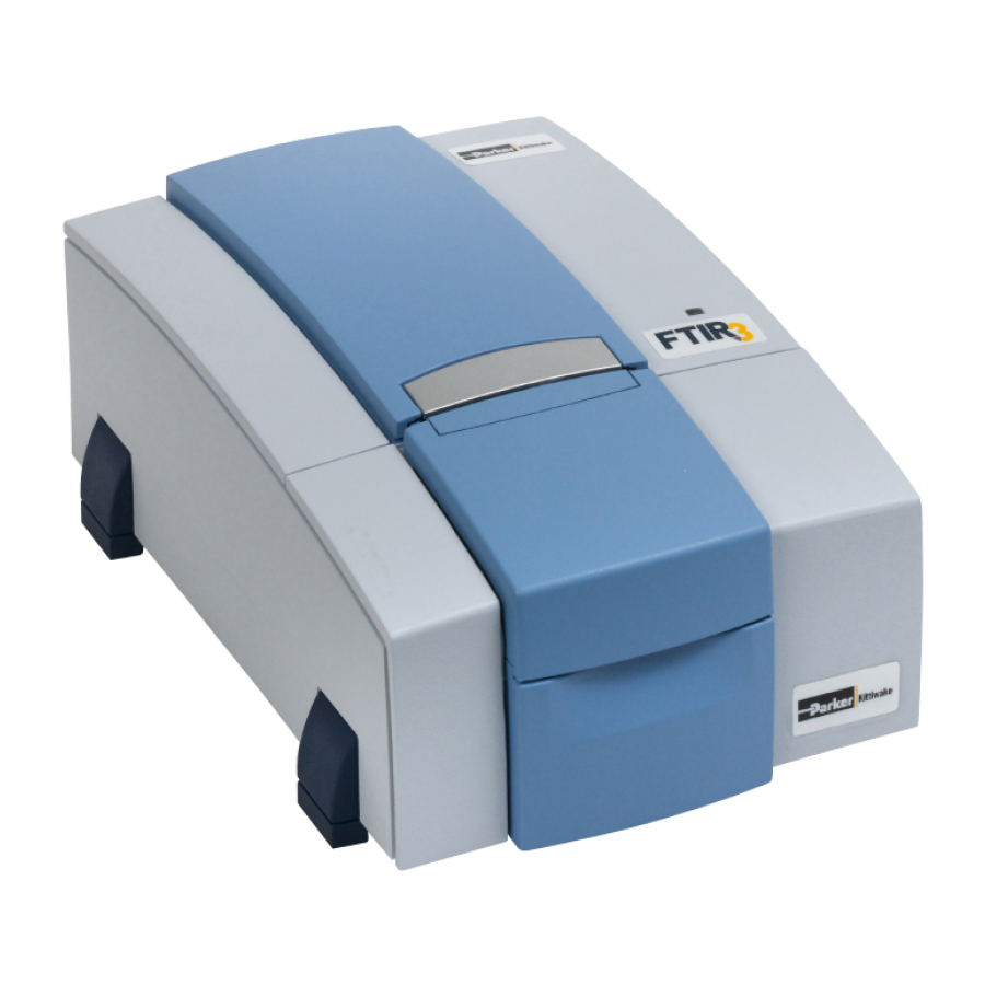
Page 11: Parts Of The Ftir3 Oil Analyzer
2.3.2 Parts of the FTIR3 Oil Analyzer Figure 2-1 Main body Status LED Sampling compartment lid (open) Sampling cell MA-K31014-KW FTIR Issue 1.indd 9 14/03/2017 20:16... -
Page 12: Rear Panel Leds
Figure 2-2 USB port (unused) Ethernet port to connect between spectrometer and computer Status LED TKD – see section 2.3.3 Status LED ACC – see section 2.3.3 Status LED DIR/ERR – see section 2.3.3 “Ext Accessory” port (unused) TAP – Test Access Port, diagnostic use only CFG dip switch. -
Page 13: Sampling Cell
Outlet Port Blanking Plug During factory calibration, each sampling cell is paired with its FTIR3 Oil Analyzer unit to ensure that the exact optical pathlength is included in the analytical calculations. For this reason, it is not recommended to use different sampling cells or interchange between units. -
Page 14: Sampling Assembly
2.3.5 Sampling Assembly To prepare the sampling assembly for use: 1. Cut an appropriate length of tubing to connect between the FTIR3 Oil Analyzer and the waste receptacle. 2. Insert in/out fitting nut and yellow ferrule. This is the OUT tubing as shown in Figure 2-4. -
Page 15: Setting Up The Ftir3
5. Launch the FTIR3 software (refer to Section 3 for complete software instructions). 6. Upon starting for the first time or after a power cycle, the FTIR3 Oil Analyzer will automatically run diagnostic self-tests. These may take up to ten minutes. -
Page 16: Sample Analysis
Figure 3-1 The top status bar will display a green icon when the spectrometer and the computer are communicating properly. If the icon is red, then verify the connections to the FTIR3 Oil Analyzer by disconnecting and reconnecting the Ethernet cable. -
Page 17: Equipment Management Screen
Before a new sample is run, the user must first define an equipment profile for the sample, by clicking icon. This will open the “View Equipment and Results” window and allow the user to enter information on the equipment, type of oil, analysis to be done, and other parameters (see Section 3.1: Equipment Management Screen for further information). -
Page 18: Creating A New Equipment File
3.1.1 Creating a new Equipment file 1.Click the icon to open the Equipment Details dialog (Figure 3-4). Figure 3-4 2. In the “Name” field, enter a name to identify the new equipment, such as “Compressor #3”. 3. Enter any pertinent Comments. (This field may be left empty if desired.) 4. -
Page 19: A)"Details" Tab
Select an equipment profile from the list in the left pane. The “Filter” field can be used to easily sort through a long list of equipment names. The information pertaining to the selected Equipment is displayed in the right-hand pane, divided into four tabs. At any time, click on the “Back”... - Page 20 Set Reference Point: Select a reference result from the list, as shown in Figure 3-8. Figure 3-8 View Analysis Information: Opens a pop-up window that displays the results of analysis (Figure 3-9). Click the check mark icon in the lower right corner to exit. Figure 3-9 Update Oil Type / Re-trend Data: This screen (Figure 3-10) allows the user to set a new oil type, and to re-trend the data collected with the parameters set in the new oil type.
- Page 21 Print Equipment Report: Prints a report showing the equipment details and trending graphs for the various parameters specified (Figure 3-11). Figure 3-11 The “Last Sample” section of the screen displays the results of the most recent sample for the selected Equipment.
-
Page 22: B) "Trend" Tab
Figure 3-12 3.1.2 (b) “Trend” Tab The Trend tab (Figure 3-13) displays the history of each oil parameter in graphic form, of percentage change from the reference plotted against the sampling interval (hours, km, etc.). Figure 3-13 Click on a parameter from the list on the left-hand side to view the graph for that parameter alone. To view multiple parameters at the same time, hold down the Ctrl key and click on the desired param- eters. -
Page 23: C) "Results" Tab
3.1.2 (c) “Results” Tab The Results tab (Figure 3-14) displays the table of results for each sample, along with the date and time the sample was analysed, and the User who performed the analysis. Figure 3-14 Click on “Percent” to display the parameter values as percentage change from the reference, or click on “Actual”... -
Page 24: Testing Mode
Clicking on the magnifying glass icon from the Options Screen will open the Sample Identification Screen (Figure 3-16). The FTIR3 Oil Analyzer is programmed with the complete range of JOAP and ASTM approved methods used for the condition monitoring of in-service lubricants. -
Page 25: Sample Identification
3.2.2 Sampling Procedure The following supplies are required to carry out the analysis of each sample: 20 ml Cleaning solution (Parker Kittiwake FTIR3 Cleaning Fluid) 5 ml Oil sample Syringe for cleaning solution (can be reused for the next sample test) - Page 26 Click the chevron button to initiate the next test sequence. Figure 3-18 5. The “Analyzing Sample” progress screen appears (Figure 3-19), indicating that the FTIR3 Oil Analyzer is scanning the sample and collecting a spectrum. Figure 3-19 6. Once the oil sample has been analysed, use a new, clean syringe to flush at least 20 ml of cleaning fluid through the cell (Figure 3-20).
- Page 27 Figure 3-20 Figure 3-21 7. Using an empty 60 ml syringe, flush air through the cell in order to clear out the cleaning fluid and make it easier to introduce the next sample. 8. The “Results” screen with component results and spectra will appear once the analysis is complete. Select the appropriate tab to view either the table of results (Results tab, Figure 3-22) or spectra (Spectra tab, Figure 3-23).
- Page 28 Figure 3-22 Figure 3-23 Alternatively, click the icon to print an Analysis Report if desired. When finished, click on the icon to save the test and return to the Setup screen for additional sample analysis. MA-K31014-KW FTIR Issue 1.indd 26 14/03/2017 20:16...
-
Page 29: Maintenance
Click on the “gear” icon to access the Oil Types and Parameters Configuration options. The FTIR3 software is preconfigured with three types of oil – Engine Oil, Gear Oil, and Transmission Oil. Oil types can be added or removed using the controls in the lower left-hand corner of the screen, below the list of oil types. - Page 30 Figure 4-2 The “Messages and Warnings” tab (Figure 4-3) allows users to define messages and warnings for the associated analysis parameters, such as cut-off types, percentage checks, as well as custom message texts and colour flags. Figure 4-3 Use the controls in the “Messages and Warnings”...
-
Page 31: Oil Parameters Tab
ASTM or JOAP-compliant results from the recorded spectra (see Section 1.1.2). CAUTION! Changing the default values and settings on this tab may invalidate the FTIR3’s results because the analysis will no longer be compliant with approved ASTM or JOAP methods and practices. -
Page 32: User Accounts
4.2.2 User Accounts The FTIR3 analysis software has two levels of account access. The “Admin” level is able to add and remove oil types, messages and warnings, and create new accounts. “User”-level accounts are restricted to running programs and oil types that are already installed. -
Page 33: Software Updates
Software Updates If the computer has access to the internet (for example via WiFi), the FTIR3 analysis software will automatically search for the latest software updates. When applicable, the user will be notified of this by a popup message when starting the program. Alternatively, when updates are available, a new button will appear in the top right corner of the Main Options screen. -
Page 34: Troubleshooting
4.7.1 FTIR3 Helper If the LED on top of the unit remains red, close the FTIR3 software and run the FTIR3 Helper program (located on the Desktop). This program will run a series of self tests, lasting up to 10 minutes and will attempt to fix any communication or firmware malfunctions. - Page 35 MA-K31014-KW FTIR Issue 1.indd 33 14/03/2017 20:17...
- Page 36 Parker Kittiwake © 2017 Parker Hannifin Corporation MA-K31014-KW Issue 1 3 - 6 Thorgate Road, Littlehampton, West Sussex BN17 7LU United Kingdom Tel: +44 (0)1903 731470 Fax: +44 (0)1903 731480 Email: kittiwakeinfo@parker.com Web: www.parkerkittiwake.com MA-K31014-KW FTIR Issue 1.indd 34 14/03/2017 20:17...
Need help?
Do you have a question about the FTIR3 and is the answer not in the manual?
Questions and answers