
Related Manuals for Parker icountLaserCM30


Summary of Contents for Parker icountLaserCM30
- Page 1 Particle Contamination Monitor (PCM) EMA-T31748 Rev.A © 2021, Parker Hannifin Manufacturing Ltd www.parker.com...
-
Page 2: Table Of Contents
Interface........................12 Materials ........................12 Exporting Test Results ....................12 Interpreting Test Results ..................12 icountLaserCM30 ....................13 icountLaserCM30 FFKM (aggressive phosphate ester compatible) ....14 icountLaserCM30 with Trace Heated Hose ............15 icountLaserCM30 with Case Mounted Pump ............16 icountAviationCM30 ....................17 Handset ........................18 Before Starting ................19 Case Contents ......................19... - Page 3 Hydraulic Connection Parts ..................62 Appendix A - Technical Drawings ..........63 Technical Drawings - icountLaserCM30 ..............63 Technical Drawings - icountLaserCM30 with Case Mounted Pump ....64 Technical Drawings - icountAviationCM30 ............65 Appendix B - Guide to Contamination Standards ......66 Introduction ......................66 Brief History ......................66...
-
Page 4: Overview
µm(c). Various cleanliness standards are in use in the hydraulic industry based on ACFTD and/or ISO MTD, and use an index scale for reporting counts as codes. Parker PCMs can be calibrated with ACFTD or ISO MTD to report a variety of cleanliness standards referencing ‘µm’... -
Page 5: Safety Information
This equipment is only to be operated by persons trained in the use and handling of pressurised hydraulic systems. Local laws and regulations for installation, operation and servicing of pressurised hydraulic systems must be adhered to. Prior to operating the unit and hoses should be inspected for damage. If any damage is found, consult with Parker accordingly. EXPLOSION An Explosion notice is used to warn of the risk of injury from high pressure system. -
Page 6: Laser Information
Exclusion of Liability Parker has made every endeavour to ensure the accuracy of the content of this document however errors cannot be ruled out. Consequently, we accept no liability for such errors as may exist or for any damage or loss whatsoever which may arise as a result of such errors. -
Page 7: Labelling
CLASS 1 LASER PRODUCT On the battery pack Nickel Metal Hydride (NiMH) Part number Serial number Waste electrical and electronic equipment (WEEE) directive CE marking Ingress protection rating Keep away from sunlight Limited operating temperature range icountLaserCM30 & icountAviationCM30 Operational Manual... -
Page 8: Principles Of Operation
Particle counts can also be shown as a contamination code, of which there are several industrial standards, in a form of a shorthand description. Online Sampling Hydraulic Schematic Outlet (P2) Bypass Loop Inlet (P1) icountLaserCM30 & icountAviationCM30 Operational Manual... - Page 9 Viton LCM302021TH /100 mL ACFTD Viton LCM302022 /100 mL ISO MTD Viton LCM302027 /100 mL ACFTD Viton LCM302028 /100 mL ISO MTD Viton LCM302064 /100 mL ISO MTD FFKM* LCM302065 /100 mL ACFTD FFKM* *Perfluoroelastomer icountLaserCM30 & icountAviationCM30 Operational Manual...
-
Page 10: Detailed Product Information
GOST: 50–100e µm = >50 µm (ACFTD) x 0.93184 GOST: 100–200e µm = >50 µm (ACFTD) x 0.06816 The instrument only uses the shorthand in these standards for reporting contamination levels. 95% confidence level using an MTD distribution with a concentration of 6mg/L. icountLaserCM30 & icountAviationCM30 Operational Manual... -
Page 11: Operating Environment
+5°C to +30°C when fitted with rechargeable battery pack, operating outside of these temperatures could result in less tests per charge When operating at low temperature the trace heating variant (LCM302021TH) may be required (consult Parker) Fluid Temperature +5°C to +80°C... -
Page 12: Interface
There are various standards in use in the hydraulic industry and most of these use an index scale for reporting counts as codes. Using ISO 4406, for example, a count of 1868677 particles is given the code ‘21’. Parker’s ‘Guide to Contamination Standards’... -
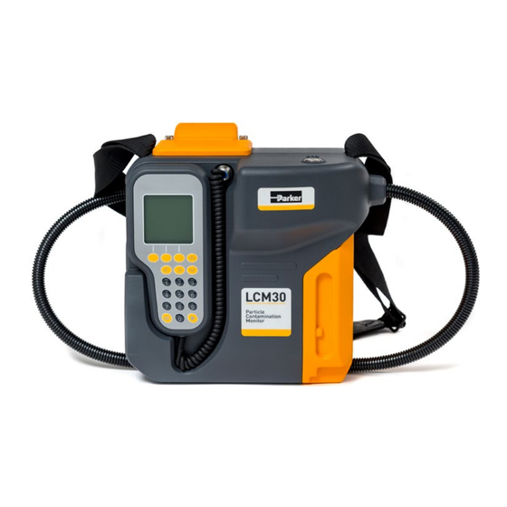
Page 13: Icountlasercm30
Printer Cover and IP Bung Hydraulic Hose Handset Rechargeable Battery Pack Back Hose Tidy P1 Inlet - Red P2 Outlet - Yellow Product Label Universal Bottle Sampler (UBS) COMMS USB-B COMMS DC Power Socket and IP Bung icountLaserCM30 & icountAviationCM30 Operational Manual... -
Page 14: Icountlasercm30 Ffkm (Aggressive Phosphate Ester Compatible)
Rechargeable Battery Pack Back Hose Tidy 5/8” BSF HSP P1 Inlet - Red 5/8” BSF HSP P2 Outlet - Yellow Product Label Universal Bottle Sampler (UBS) COMMS USB-B COMMS DC Power Socket and IP Bung icountLaserCM30 & icountAviationCM30 Operational Manual... -
Page 15: Icountlasercm30 With Trace Heated Hose
Trace Heated Hose Online Sampling with Trace Heated Hose Hydraulic Schematic Heating element Outlet (P2) Moisture and temperature sensor Bypass Flow probe Loop Flowcell Inlet (P1) Laser diode Photo diode Changeover valve Stepper motor Dual direction syringe pump... -
Page 16: Icountlasercm30 With Case Mounted Pump
Case Mounted Pump Offline Sampling with Case Mounted Pump (CMP) Hydraulic Schematic Waste container Outlet (P2) Test sample Bypass Loop Case mounted pump (CMP) Inlet (P1) Moisture and temperature sensor Flow probe Flowcell Laser diode Photo diode Changeover valve... -
Page 17: Icountaviationcm30
Product Label Case Mounted Pump (CMP) Blanking Hose P1 Inlet - Red Outlet (Bottle Sampling) Inlet (Bottle Sampling) P2 Outlet - Yellow Universal Bottle Sampler (UBS) COMMS USB-B COMMS DC Power Socket and IP Bung icountLaserCM30 & icountAviationCM30 Operational Manual... -
Page 18: Handset
Handset LCD Backlit Display Function Keys Directional Arrow Keys Shortcut Key to Home Screen Shortcut Key to Start Test Screen icountLaserCM30 & icountAviationCM30 Operational Manual... -
Page 19: Before Starting
1 Power Supply & Regional Power Cable 1 Calibration Certificate NOTE: The original packaging must not be disposed of as this is required to return the PCM safely to a Parker Service Centre (see www.parker.com) for re-calibration and/or servicing. icountLaserCM30 Operational Manual... -
Page 20: Powering The Pcm
Very Low Empty NOTE: The battery pack is not charged while fitted onto the PCM and can only be charged when removed. NOTE: Additional battery packs can be purchased separately (see Accessories / Parts List). icountLaserCM30 & icountAviationCM30 Operational Manual... -
Page 21: Powering On The Pcm For The First Time
30 Grace Days Left www.Parker .com/unlock LCM30 Menu Press OK to Continue Start Test Test Result(s) Search Results Tools Settings Select Thank You for Registering your LCM30 LCM30 Menu Start Test Test Result(s) Search Results Tools Settings Select icountLaserCM30 & icountAviationCM30 Operational Manual... -
Page 22: Setting Time & Date
Select Done to save changes and exit edit mode. Select Reset to revert to default settings or Cancel to exit edit mode. Note: All parameters set will be saved even when the unit is powered off. icountLaserCM30 & icountAviationCM30 Operational Manual... -
Page 23: Connection
Connection The Parker System 20 Sensor is an inline manifold enabling a safe and simple method of connecting an LCM30 to an online pressurised hydraulic system (2 bar minimum system pressure, 2 to 100 cSt working viscosity). Accessories / Parts List for System 20 Sensor variants. - Page 24 5 minutes to allow the fluid condition to stabilise before starting a test. When disconnecting the LCM30 from the System Step 6 20 Sensor, P1 and P2 must be undone at the same time. icountLaserCM30 & icountAviationCM30 Operational Manual...
-
Page 25: Single Point Sampler
LCM30 to be connected to an online pressurised hydraulic system via a single test point. Accessories / Parts List for Single Point Sampler variants. The LCM30 is supplied filled with hydraulic oil and will require flushing prior to use. HYDRAULIC SYSTEM Drain Reservoir Single Point Sampler (SPS) LCM30 icountLaserCM30 & icountAviationCM30 Operational Manual... - Page 26 Flow Check. Replicate steps until flow rate is ‘good’. Disconnecting LCM30 from SPS • Ensure SPS valve is open. • Disconnect LCM30 P1 from hydraulic system • Disconnect LCM30 P2 from SPS. icountLaserCM30 & icountAviationCM30 Operational Manual...
-
Page 27: Quick Test
: 48% RH 16°C Change Change Print Back Print Back Size Counts Code / Std / Std ≥4 102719 ≥6 22200 ≥14 3391 ≥21 1685 ≥38 ≥70 ≥3e Sizes are equivalent diameter µm(c) Particle counts are per 100mL icountLaserCM30 & icountAviationCM30 Operational Manual... -
Page 28: Menu Navigation
Test n of n and Test No. displayed. Test 1 of 1 Please wait for test to complete. Test No: 1 Note: If a test is unsuccessful refer to the Error Please Wait Codes section for guidance. icountLaserCM30 & icountAviationCM30 Operational Manual... - Page 29 ≥70 ≥3e ISO 4406 Note: Default date format can be set under Change Print Back Settings / Time & Date / Std Test: 1 RUN 1 Date: 13/05/20 Time: 08:47 Change Print Back / Std icountLaserCM30 & icountAviationCM30 Operational Manual...
- Page 30 Note: If a test is unsuccessful refer to the Change Print Back / Std Error Codes section for guidance. Test: 1 47%RH 18°C NAS 1638 Change Print Back / Std Test: 1 Class 99 47%RH 18°C AS4059 (cpc) Change Print Back / Std icountLaserCM30 & icountAviationCM30 Operational Manual...
-
Page 31: Multiple Test
Note: For continuous testing without any time delay between consecutive tests, select a Test Period of 0 mins. Note: The last Test Period will be selected by default. Note: 100 minutes is the maximum Test Period. icountLaserCM30 & icountAviationCM30 Operational Manual... - Page 32 Note: Press Stop to cancel testing. Note: All previous test results can be displayed by pressing Result and using the keys to scroll – Multiple Test mode will continue in background. icountLaserCM30 & icountAviationCM30 Operational Manual...
- Page 33 Settings / Test Options / Standards ISO 4406 Change Print Back / Std Test: 1 47%RH 18°C NAS 1638 Change Print Back / Std Test: 1 11A/6B/8C/ 10D/12E/11 47%RH 18°C AS4059 (cpc) Change Print Back / Std icountLaserCM30 & icountAviationCM30 Operational Manual...
-
Page 34: Ip564 Test
RUN 1 When finished, select Start to start test. Start Back Note: A Test ID is not required to start a test. Note: The Test ID will be used until a new Test ID is entered. icountLaserCM30 & icountAviationCM30 Operational Manual... - Page 35 Note: If a test is unsuccessful refer to the Test Progress Error Codes sections for guidance. IP564 Test Phase Sample 2 Test No: 1 Please Wait Test Progress IP564 Test Phase Sample 3 Test No: 1 Please Wait icountLaserCM30 & icountAviationCM30 Operational Manual...
- Page 36 Note: Default date format can be set under Settings / Time & Date Print Back % by Volume Size ≥4-6 ≥6-14 ≥14-21 ≥21-25 ≥25-30 ≥30 Print Back Test: 1 RUN 1 Date: 13/05/20 Time: 08:47 Print Back icountLaserCM30 & icountAviationCM30 Operational Manual...
-
Page 37: Test Result(S)
Note: Default date format can be set under ≥3e ≥70 ISO 4406 Settings / Time & Date Change Print Back / Std Test: 5 RUN 1 Date: 13/05/20 Time: 08:47 Change Print Back / Std icountLaserCM30 & icountAviationCM30 Operational Manual... -
Page 38: Search Results
Use the keys and keypad to enter the Back search criteria. Search Results Note: The available search range is displayed. Date Find by: From: 24/02/20 – 13/05/20 Back Search Results Find by: (38 Saved Tests) Back icountLaserCM30 & icountAviationCM30 Operational Manual... - Page 39 Settings / Test Options / ISO 4406 Standards Change Print Back / Std Test: 5 47%RH 18°C NAS 1638 Change Print Back / Std Test: 5 11A/6B/8C/ 10D/12E/11 47%RH 18°C AS4059 (cpc) Change Print Back / Std icountLaserCM30 & icountAviationCM30 Operational Manual...
-
Page 40: By Test Number
5 Results Found Press View to view all test results and use the keys to scroll through tests. Print View Back Note: Only the tests found within the search criteria will be available for printing and viewing. icountLaserCM30 & icountAviationCM30 Operational Manual... -
Page 41: By Test Date
5 Results Found Press View to view all test results and use the keys to scroll through tests. Print View Back Note: Only the tests found within the search criteria will be available for printing and viewing. icountLaserCM30 & icountAviationCM30 Operational Manual... -
Page 42: Search By Id
8 Results Found Press View to view all test results and use the keys to scroll through tests. Print View Back Note: Only the tests found within the search criteria will be available for printing and viewing. icountLaserCM30 & icountAviationCM30 Operational Manual... -
Page 43: Tools
Tools available will be dependent on product Step 2 Tools variant. Flow Check Humidity & Temp Use the keys to select the required Tool Pump and then press Select. Heated Hose Note: The selection is shown in larger text. Select Back icountLaserCM30 & icountAviationCM30 Operational Manual... -
Page 44: Flow Check
Low Flow Rate indicates that there is insufficient flow and the unit is unable to operate. Ensure the bypass loop refer to schematic flow rate is greater than 15 mL/min. icountLaserCM30 & icountAviationCM30 Operational Manual... -
Page 45: Checking Humidity & Temperature
Select OK to return to the Tools menu. Heated Hose Note: Measurements are taken every 1 second. Select Back Note: Data for information only and is not a Humidity & Temp requirement for initiating a test. Humidity: 52%RH Temperature: 22°C icountLaserCM30 & icountAviationCM30 Operational Manual... -
Page 46: Pump
30mL/min of fluid through the bypass loop Pump (refer to schematic) Pump: Fitted User: Enabled Speed: Flush Use keys < or > Pump Running Back Pump Pump: Fitted User: Enabled Speed: Flush Use keys < or > Pump Running Back icountLaserCM30 & icountAviationCM30 Operational Manual... -
Page 47: Heated Hose
Heated Hose (For trace heated hose power options consult with Parker) The heated hose is for use in cold operating conditions. Description Visual Step 1 Selecting the Heated Hose tool will enable the Tools user to manually operate the Trace Heated Hose. -
Page 48: Settings
Setting Handset Options and then press Select. Time & Date Power / Battery Calibration Info Note: There are two screens displaying the Settings menus. Select Back Settings Product Info Select Back icountLaserCM30 & icountAviationCM30 Operational Manual... -
Page 49: Test Options / Standards
Select OK to save changes and return to the Test Options menu. Note: Test standards will differ between product variants. Note: All parameters set will be saved even when the unit is powered off. icountLaserCM30 & icountAviationCM30 Operational Manual... -
Page 50: Test Options / Result Reporting
Decimal: Either a full stop (period) or comma can be selected to indicate a decimal place. Select OK to save changes and return to the Test Options menu. Note: All parameters set will be saved even when the unit is powered off. icountLaserCM30 & icountAviationCM30 Operational Manual... -
Page 51: Pump Options
Note: When set to Disabled the pump will not operate when a test is started. Note: All parameters set will be saved even when the unit is powered off. icountLaserCM30 & icountAviationCM30 Operational Manual... -
Page 52: Test Options / Delete Tests
All tests deleted is displayed. Note: It is not possible to delete individual tests. Delete All Tests? Delete Tests Are you sure you want to permanently delete ALL tests? Delete Tests ALL Tests deleted icountLaserCM30 & icountAviationCM30 Operational Manual... -
Page 53: Handset Options
OK Reset Select Reset to revert to default settings. Note: The contrast has a range between 2 (light) to 16 (dark). Note: All parameters set will be saved even when the unit is powered off. icountLaserCM30 & icountAviationCM30 Operational Manual... -
Page 54: Time & Date
Select Done to save changes and exit edit mode. Select Reset to revert to default settings or Cancel to exit edit mode. Note: All parameters set will be saved even when the unit is powered off. icountLaserCM30 & icountAviationCM30 Operational Manual... -
Page 55: Power / Battery
Note: When mains power is supplied the battery will not be charged - refer to Section Powering The PCM for charging. Note: All parameters set will be saved even when the unit is powered off. icountLaserCM30 & icountAviationCM30 Operational Manual... -
Page 56: Calibration Info
Note: The selection is shown in larger text. Time & Date Power / Battery Calibration Info Select Back Calibration data is displayed. Step 2 Calibration Info Cal Dust: Select OK to return to the Settings menu. Cal Date: 12/07/20 Cal Due: 13/07/21 icountLaserCM30 & icountAviationCM30 Operational Manual... -
Page 57: Product Info
Note: The selection is shown in larger text. Settings Product Info Select Back Step 2 Product Info data is displayed. Product Info Product: LCM30 Select OK to return to the Settings menu. Version: 1.00 Part: LCM302022 S/N: GO.6NA.01 icountLaserCM30 & icountAviationCM30 Operational Manual... -
Page 58: Maintenance
Maintenance The PCM must not be disassembled. No user-serviceable parts are contained within. Contact the local Parker Service Centre (see www.parker.com) for maintenance and re-calibration queries. Cleaning A damp, soft cloth should be used to clean the exterior of the PCM. Aggressive chemicals must not be used to clean the PCM. -
Page 59: Servicing / Re-Calibration
Press OK to Continue Any service or repair work must be carried out by a Parker approved Service Centre (see www.parker.com). Contact the local Parker Sales Company (see www.parker.com) for re-calibration details. The recommended period between re-calibration is 12 months. -
Page 60: Error Codes
Cause Action 1. Turn the PCM Off/On and repeat test 1. Unknown Fault Unknown fault Unknown 2. Consult with Parker if issue persists User aborted 1. Turn the PCM Off/On and repeat test 2. User Abort Unknown test 2. Consult with Parker if issue persists 1. - Page 61 Fast 2. Variable system viscosity during test test too fast pressure during test 3. Consult with Parker if issue persists 14. Oil Volume too Measured fluid 1. Turn the PCM Off/On and repeat test Multiple Small volume too small 2.
-
Page 62: Reference
Reference Accessories / Parts List To order accessories and parts, contact local Parker Sales Company (see www.parker.com). Accessory Part Number Description ACC6NA001 CM30 BATTERY PACK ACC6NA002 CM30 EMPTY BATTERY PACK ACC6NA003 CM30 POWER ADAPTER ACC6NA004 UBS CM30 CONTROL CABLE ACC6NA005... -
Page 63: Appendix A - Technical Drawings
Appendix A Technical Drawings icountLaserCM30 291 mm 508 mm Weight <7.5kg NOTE: Reference dimensions only. icountLaserCM30 & icountAviationCM30 Operational Manual... -
Page 64: Technical Drawings - Icountlasercm30 With Case Mounted Pump
Technical Drawings icountLaserCM30 with Case Mounted Pump 291 mm 380 mm 129 mm Weight <9kg NOTE: Reference dimensions only. icountLaserCM30 & icountAviationCM30 Operational Manual... -
Page 65: Technical Drawings - Icountaviationcm30
Technical Drawings icountAviationCM30 51 mm 291 mm 355 mm 82 mm Weight <8.5kg NOTE: Reference dimensions only. icountLaserCM30 & icountAviationCM30 Operational Manual... -
Page 66: Appendix B - Guide To Contamination Standards
µm(c). This is different to the direct linear measurement (chord length) seen with ACFTD particle size classification. Therefore, particle sizes were reported as being either ‘µm’ or ‘µm(c)’ depending on the calibration standard followed i.e. ISO 11171, ISO 11943, ISO 21018-4 or ISO 4402 etc. icountLaserCM30 & icountAviationCM30 Operational Manual... -
Page 67: Contamination Basics
70 µm Limit of human visibility (naked eye) 40 µm Milled flour 25 µm Red blood cells 8 µm Bacteria 2 µm NOTE: One micron (μm) equals one thousandth of a millimetre (1μm = 0.001mm). icountLaserCM30 & icountAviationCM30 Operational Manual... -
Page 68: Iso Codes (Hydraulic Fluid Contamination)
500 000 130 000 250 000 64 000 130 000 32 000 64 000 16 000 32 000 8 000 16 000 4 000 8 000 2 000 4 000 1 000 2 000 1 000 icountLaserCM30 & icountAviationCM30 Operational Manual... -
Page 69: Suggested Acceptable Contamination Levels
High performance Super critical 15 / 13 / 09 reliability servovalves Laboratory or aerospace NOTE: The three figures of the ISO code numbers represent ISO level contamination grades for particles of >4µm(c), >6µm(c) and >14µm(c) respectively. icountLaserCM30 & icountAviationCM30 Operational Manual... -
Page 70: Iso Codes (Fuel Contamination)
– Fuel ISO MTD 4µm(c) 6µm(c) 14µm(c) 21µm(c) 25µm(c) 30µm(c) Industry conventionally reports raw particle counts as per 100ml for hydraulic fluids, and per mL for fuel, though this is not part of any standard. icountLaserCM30 & icountAviationCM30 Operational Manual... -
Page 71: Nas 1638 Table
11 400 2 025 128 000 22 800 4 050 256 000 45 600 8 100 1 440 512 000 91 000 16 200 2 880 102 4000 182 400 32 400 5 760 1 024 icountLaserCM30 & icountAviationCM30 Operational Manual... -
Page 72: Nav Air 01-1A-17 Table
22 / 20 / 13 22 / 20 / 17 23 / 21 / 14 15 000 23 / 21 / 18 24 / 22 / 15 21 000 25 / 23 / 17 100 000 icountLaserCM30 & icountAviationCM30 Operational Manual... -
Page 73: Ppm Conversion Table
= 1 µL in 1 litre Example 1 400 PPM in 1 litre = 400 µL Example 2 A reading of 250 PPM equates to a quantity of absorbed water in a 400 litre capacity system of 0.1 litre. icountLaserCM30 & icountAviationCM30 Operational Manual... -
Page 74: Appendix C - Eu Declaration Of Conformity
Directives. The person named below is responsible for compiling the Technical Documentation Place of issue: Littlehampton, England Date of issue: 25 January 2021 Andrew Baldwin Engineering Manager DOC-T32111 REV.- CM30 Declaration of Conformity icountLaserCM30 & icountAviationCM30 Operational Manual... -
Page 75: Appendix D - Parker Worldwide Contact Details
(from AT, BE, CH, CZ, DE, DK, EE, ES, FI, PT – Portugal FR, IE, IL, IS, IT, LU, MT, NL, NO, PL, PT, RU, Tel: +351 22 999 7360 SE, SK, UK, ZA) © 2021 Parker Hannifin Corporation. All rights reserved. icountLaserCM30 & icountAviationCM30 Operational Manual...
Need help?
Do you have a question about the icountLaserCM30 and is the answer not in the manual?
Questions and answers