
Related Manuals for Parker OSP-P


Summary of Contents for Parker OSP-P
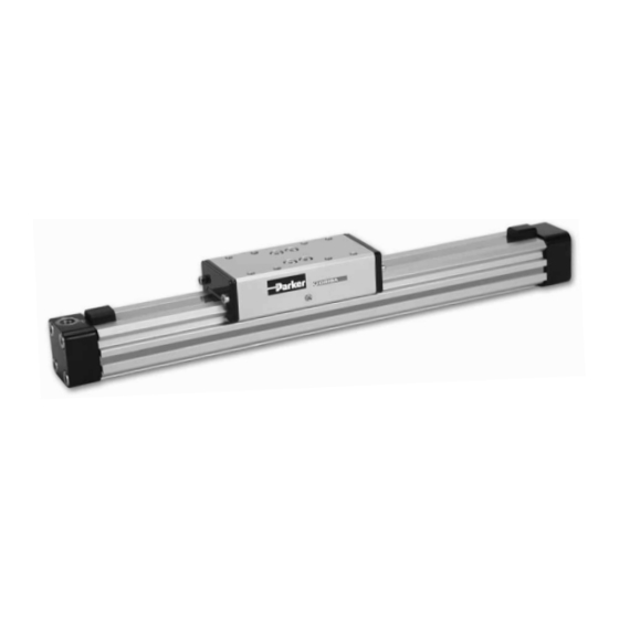
- Page 1 Modular Pneumatic Linear Drive System OSP-P / OSPP-BG Operating Instructions ORIGA SYSTEM PLUS...
-
Page 2: Table Of Contents
Cylinder OSP-P Reassembly (not Clean Room Cylinder) .............. 21 Cylinder OSPP-BG Reassembly ....................27 Trouble shooting List of faults .......................... 31 Cleaning the Inner Sealing Band OSP-P (not Clean Room Cylinder) ..........32 Cleaning the Inner Sealing Band OSPP-BG ................33 Removal / Disposal Declaration of Incorporation Spare Parts Lists OSP-P Ø... -
Page 3: Foreword To The Operating Instructions
Foreword to the Operating Instructions The purpose of these Operating Instructions is to assist you in familiarising yourself with the OSP-P and to make use of the functions it has been designed for. The following instruction describes various types of actuators. They are marked with the following pictograms... -
Page 4: Safety
Please inform us immediately of any recurring malfunctions or problems with the OSP-P / OSPP-BG. Safety 2.1 Authorized Use The operating safety of the OSP-P / OSPP-BG (called “Linear Drive”) is only guaranteed if it is used in au- thorized applications. Authorized applications of the Linear Drive are: •... -
Page 5: Warranty
Linear Drive. This identification plate shall not be removed or destroyed in any way. A liability of Messrs Parker Hannifin GmbH – irrespective of the legal reason – exists only in the event of intentional or gross negligence, culpable injury to life, body, health, in the event of deficiencies with malicious intent of deception or faults the absence of which has been expressly guaranteed. -
Page 6: Transport And Assembly
Information Transport damage and missing parts are to be reported immediately and in packed writing to the transport company or to Parker Hannifin GmbH or to the delivery company. Storage Where storage or interim storage is involved, you must observe the following: •... -
Page 7: Technical Description Of The Linear Drive Osp-P
Design and Function 6.2.1 Design Features OSP-P, Linear Drive Ø10 • The OSP-P is a pneumatic cylinder without piston rod. • The longitudinal slot in the cylinder is sealed and protected by stainless steel bands. • The piston consists of piston yoke, support rings, sealing bands, piston seals, bearing strips and mag- nets on the inside. - Page 8 Modular Pneumatic Linear Drive System OSP -P / OSPP-BG 6.2.3 Design Features OSP-P, Linear Drive Ø16 to Ø80 • The OSP-P is a pneumatic cylinder without piston rod. • The longitudinal slot in the cylinder is sealed and protected by stainless steel bands. •...
-
Page 9: Technical Description Of Clean Room Cylinder Osp-P
The longitudinal slot in the cylinder is sealed and protected by stainless steel bands. • The difference between the clean room cylinder OSP-P and the rodless standard linear drive OSP-P is that a vacuum is created between the internal and the external steel band. -
Page 10: Technical Description Of Basic Guide Ospp-Bg Technical Data
• forces and loads • speeds and cushioning energy • weights and additional data see catalogue OSP-P. Operating pressure range: = 8 bar. Compressed air requirements: Free of water and dirt. Additional lubrication with oil mist is not necessary. - Page 11 OSPP-BG Piston yoke (27a) Guide carriage (56) Outer sealing band (11) Wiper (48) Felt (49) (A-Band) Wiper cover inner, outer Inner band sealing (17) (50, 51) (I-Band) End cap right (35) Cushion spigot (20) End cap left (35) Air connection Cylinder barrel (1a) Support ring (25) Piston seal (24) Integrated grease nipple...
-
Page 12: Installation In Machine Or Plant Of Osp-P / Ospp-Bg
Position the working load so that the bending moments on the carrier are below the values shown in the OSP-P cataloque. • For long cylinders, use mid-section supports from our OSP-P cataloque. OSP-P only: • Avoid forces exerted by loads carried on external linear guides. -
Page 13: Connection Diagram
Magnetic switches, offered in our catalogue, allow contactless position sensing of the linear drives in their intermediate and end positions. For further information refer to the OSP-P catalogue. T-Slot Magnetic Switches P8S Profilrohr Basic Guide 25 Profilrohr Basic Guide 32... -
Page 14: Commissioning
Unscrew both needle valves about one half turn (not Ø 10). • In the case of clean room cylinders OSP-P switch on suction device before venting the cylinder. • Slowly pressurise both cylinder chambers in order to prevent uncontrolled, dangerous movements (soft start valve, accessories in our catalogue), the piston stops after a short movement. -
Page 15: Re-Commissioning A Linear Drive After Long Periods Without Operation
Continue as for individual linear drives (chap. 10 on page 14). Removal from plant Crushing hazard and danger of eye injuries. Be extremely careful when removing OSP-P from the plant. Observe chapter „2 Safety“ on page 4 and the local safety regulation. Possible hazards are: •... -
Page 16: Service / Maintenance
Dismantle the required parts in order to be able to freely move the piston / guide carriage. If necessary, completely remove the linear drive. • Switch off the main switch and secure it against unintentional switching-on. 12.1 Maintenance intervals Information only for OSP-P (Standard) and OSPP-BG km operated Maintenance Instructions OSP-P Dismantle linear drive completely if necessary, clean parts see chap. -
Page 17: Maintenance
Procedure: • Depressurise cylinder / plant. • Remove load. 13.2 Dismantle OSP-P Ø 10 Check the position of the parts as shown on the exploded view drawing chap. 17.1 on page 35. Dismantle the endcap • Remove two locking screws (13) for outer band, (11) on both ends. -
Page 18: Dismantle Osp-P Ø 16 Up To Ø 80
Modular Pneumatic Linear Drive System OSP -P / OSPP-BG 13.3 Dismantle OSP-P Ø 16 up to Ø 80 Check the position of the parts on the exploded view drawing chap. 17.2 on page 35. 13.3.1 Remove end cap • Remove screws (36) and end caps (35) and remove end caps (35) on both sides. -
Page 19: Dismantle Ospp-Bg (Basic Guide)
13.4 Dismantle OSPP-BG (Basic Guide) Check the position of the parts on the exploded view drawing chap. 17.3 on page 36. 13.4.1 Replacement of the slide profiles only Dismantle Guide Carriage • Move guide carriage (56) to middle position. • Remove the screws (52) from the wiper covers (50, 51). - Page 20 Modular Pneumatic Linear Drive System OSP -P / OSPP-BG Assembly of the Wiper Covers • Lubricate the felts (49) with the grease for guidance (IDENT-NO. 10550FIL) • Insert the wipers (48) and the felts (49) into the inner wiper cover (59). The sealing lip of the wiper must be outwards (see drawing).
-
Page 21: Cylinder Osp-P Reassembly (Not Clean Room Cylinder)
• Take piston out again. Grease cylinder barrel: • Grease inside of cylinder bore as far as you can reach (Parker Origa-grease) see chap. „17.9 Lubrication“ on page 39. • Grease the two support rings and piston behind support rings. - Page 22 Modular Pneumatic Linear Drive System OSP -P / OSPP-BG Fitting the End Caps • Insert clamping pieces for the inner sealing band (16) into the endcap. Observe installation position. bevel must face towards the air connection. • Insert clamping pieces for outer band (14) into the cover. •...
- Page 23 13.5.2 OSP-P Ø16 to Ø80 Check the position of the parts on the exploded view drawing chap. 17.3 on page 36. Inserting the magnet strips (see diagram) With cylinders from Ø 40 the magnet strips can slip out of the cylinder barrel.
- Page 24 Modular Pneumatic Linear Drive System OSP -P / OSPP-BG Install the piston Information Piston seals have a sensitive sealing lip which should only be inserted into the cylinder barrel by pulling ac- tion. For that reason the fitting sequence must be carried out as follows: •...
- Page 25 Insert cushion spigot (20) and install endcap • Grease O-ring grooves (21), insert O-rings and grease them. • Grease cushioning spigots (20). • Place inlay nuts (26) in cushioning spigots with ridges upwards. • Push cushioning pad (22) on to cushioning spigot (20), mind the correct installation position, bore hole at the cushion spigot must not be closed.
- Page 26 Modular Pneumatic Linear Drive System OSP -P / OSPP-BG Checking Tension of inner Sealing Band Inner sealing band must be fitted: • Without pretension. • Without hanging loose. Complete the Cylinder Information See the table „Torque Moments for screws“ on page 24. •...
-
Page 27: Cylinder Ospp-Bg Reassembly
13.6 Cylinder OSPP-BG Reassembly Check the position of the parts on the exploded view drawing chap. 17.3 on page 36 Danger of injuries The sealing bands, especially the inner sealing band are very sharp-edged. Wear gloves! Preparation: • Clean and dry sealing bands and cylinder barrel. •... - Page 28 Modular Pneumatic Linear Drive System OSP -P / OSPP-BG Install the piston Information Piston seals have a sensitive sealing lip which should only be inserted into the cylinder barrel by pulling action. For that reason the fitting sequence must be carried out as follows: •...
- Page 29 Install Guide Carriage • Push the complete guide carriage (56) carefully onto the cylinder barrel (1). Make sure, that the guide carriage does not scratch on the cylinder barrel. • Push the inner wiper cover (50) and then the outer wiper cover (51) onto the cylinder barrel. Insert cushion spigot (20) and install endcap •...
- Page 30 Modular Pneumatic Linear Drive System OSP -P / OSPP-BG Checking Tension of inner Sealing Band Inner sealing band must be fitted: • Without pretension. • Without hanging loose. Complete the Cylinder OSPP-BG Information See the „Torque Moments“ for screws of table on page 19 and page 28. •...
-
Page 31: Trouble Shooting
Trouble shooting Faulty OSP-P clean room cylinders must be returned to the manufacturer! 14.1 List of faults For instructions please refer to chapters: Standard Clean Room Basic Guide Fault description Possible cause Remedy Cylinder leaks somewhere 14.2 on 14.3 on along the inner sealing Inner sealing band (17) dirty. -
Page 32: Cleaning The Inner Sealing Band Osp-P (Not Clean Room Cylinder)
Modular Pneumatic Linear Drive System OSP -P / OSPP-BG 14.2 Cleaning the Inner Sealing Band OSP-P (not Clean Room Cylinder) Dirt particles can lodge between the inner sealing band and the cylinder bore and cause leakage. Cleaning is then required. -
Page 33: Cleaning The Inner Sealing Band Ospp-Bg
14.3 Cleaning the Inner Sealing Band OSPP-BG Dirt particles can lodge between the inner sealing band and the cylinder bore and cause leakage. Cleaning is then required. Warning! Danger of eye injury ! Wear safety glasses where indicated! • There is danger of eye injury from flying dirt particles. Danger of cuts on fingers etc. -
Page 34: Declaration Of Incorporation
DIN EN 983, Veiligheidstechnische eisen ten aanzien van vloeistoftechnische installaties en componenten. Een Technische Documentatie is volledig beschikbaar. Het is verboden, de OSP-P in gebruik te nehmen totdat is vastgesteld, dat de machine/installatie, waarin de lineaire aandrijvingen ingebouwd moeten worden, voldoet aan de bepalingen van de EG-Machinerichtlijn. -
Page 35: Spare Parts Lists
Spare Parts Lists 17.1 OSP-P Ø 10 Item-Number 17.2 OSP-P Ø16 to Ø80 Item-Number... -
Page 36: Ospp-Bg
Modular Pneumatic Linear Drive System OSP -P / OSPP-BG 17.3 OSPP-BG Item-Number... -
Page 37: Replacement Parts (Not Osp-P Clean Room Cylinder)
17.4 Replacement Parts (not OSP-P Clean Room Cylinder) IDENT-NO. * ITEM. Ø10 ITEM. Ø16-80 DESCRIPTION Ø 10 Ø 16 Ø 25 Ø 32 Ø 40 Ø 50 Ø 63 Ø 80 8,18,24,28 7,8,18,19,21 SEAL KIT STANDARD 3083 11052 11053 11054 11055 11056 11057 11058 22,23,24,28,31 (INC. -
Page 38: Replacement Parts (Not Osp-P Clean Room Cylinder)
Modular Pneumatic Linear Drive System OSP -P / OSPP-BG 17.7 Replacement Parts (not OSP-P Clean Room Cylinder) IDENT-NO. * ITEM. DESCRIPTION Ø 10 Ø 16 Ø 25 Ø 32 Ø 40 Ø 50 Ø 63 Ø 80 CyLINDER BARREL WITH MAGNETSTRIP... -
Page 39: Replacement Parts Ospp-Bg
Replacement Parts (continued) IDENT-NO. * ITEM. DESCRIPTION Ø 10 Ø 16 Ø 25 Ø 32 Ø 40 Ø 50 Ø 63 Ø 80 SCREW FOR END CAP 0735 10136 10033 10282 0858 1202 10377 10589 SCREW FOR END CAP STAINLESS 0795 10328 10046 10283 0859... - Page 40 Tel: +27 (0)11 961 0700 Tel: +36 1 220 4155 parker.southafrica@parker.com parker.hungary@parker.com © 2011 Parker Hannifin Manufacturing Germany GmbH & Co. KG - The right to introduce technical modifications is reserved P-A7P013E 09/2011 Parker Hannifin Manufacturing Germany GmbH & Co. KG Pneumatic Division Europe –...
Need help?
Do you have a question about the OSP-P and is the answer not in the manual?
Questions and answers