Table of Contents
Advertisement
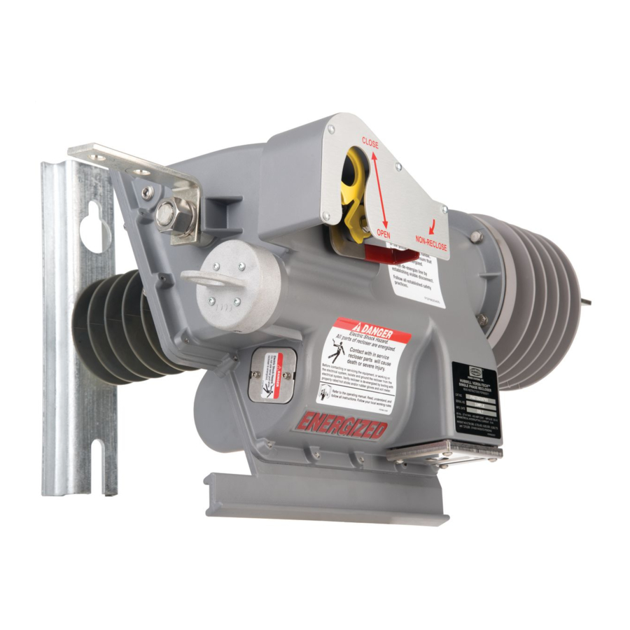
Versa-Tech® I & Versa-Tech® LT
Single-Phase Recloser
Installation, Operation and Maintenance Manual
Hubbell has a policy of continuous product improvement. Please visit hubbellpowersystems.com to confirm current design specifications.
1615 Moores Street | Leed, AL 35094 | (573) 682-5521
©2020 Hubbell Incorporated | hpsliterature@hubbell.com | hubbellpowersystems.com
PSP8620311 Rev G
Advertisement
Table of Contents

Related Manuals for Hubbell Versa-Tech I


Summary of Contents for Hubbell Versa-Tech I
- Page 1 Versa-Tech® I & Versa-Tech® LT Single-Phase Recloser Installation, Operation and Maintenance Manual Hubbell has a policy of continuous product improvement. Please visit hubbellpowersystems.com to confirm current design specifications. 1615 Moores Street | Leed, AL 35094 | (573) 682-5521 ©2020 Hubbell Incorporated | hpsliterature@hubbell.com | hubbellpowersystems.com...
- Page 2 Hubbell Power Systems, Inc. The warranty in the terms and conditions of sale is the sole warranty of Hubbell Power Systems, Inc. Any statements in this document do not create new warranties or modify any existing warranty.
-
Page 3: Table Of Contents
Customer Supplied Requirements Return Kit Packaging Instructions Software Installation Appendix A : Nameplate Connecting Recloser to PC Bracket Installation To Establish Communications Connecting Local Radio Connecting to WiFi Remote Radio Power ©2021 Hubbell Incorporated | PSP8620311 Versa-Tech® VTI & VTLT Instruction Manual REV G... - Page 4 Recloser attached to high potential test set Figure 7-2 Recloser attached to high current test set Figure 8-1 Battery bayonet in the recloser Figure 8-2 Battery bayonet partially removed from recloser ©2021 Hubbell Incorporated | PSP8620311 Versa-Tech® VTI & VTLT Instruction Manual REV G...
-
Page 5: Safety Information
CAUTION used without the safety alert symbol indicates a potentially hazardous situation which, if not avoided, may result in property damage. ©2021 Hubbell Incorporated | PSP8620311 Versa-Tech® VTI & VTLT Instruction Manual REV G... -
Page 6: Ratings And Specifications
4 = Single Tap Lug 2 = 3 Pole Plaques 5 = Double Tap Lug 3 = 4 Pole Plaques Installation Alternatives Figure 1-1 Figure 1-2 Pole/Structure Face Mounting Crossarm Mounting ©2021 Hubbell Incorporated | PSP8620311 Versa-Tech® VTI & VTLT Instruction Manual REV G... -
Page 7: Dimensions - Pole/Structure Mount
LOCKOUT INDICATOR BEACON AND COUNTER 22.0 15.8 Side View 15.0 OPERATING LEVER BATTERY PACK (HOT STICK REPLACEABLE) SERIAL PROGRAMMING PORT LOCKOUT INDICATOR BEACON AND COUNTER LEAKAGE DISTANCE - 39.4" ©2021 Hubbell Incorporated | PSP8620311 Versa-Tech® VTI & VTLT Instruction Manual REV G... -
Page 8: Dimensions - Crossarm Mount
LEAKAGE DISTANCE - 39.4" 12.7 14.0 24.9 2-HOLE NEMA PAD (STANDARD) TYPICAL VACUUM INTERRUPTER LOCKOUT INDICATOR BEACON AND COUNTER NON-RECLOSE LEVER LOCKOUT INDICATOR BEACON AND COUNTER OPERATING LEVER Front View Side View ©2021 Hubbell Incorporated | PSP8620311 Versa-Tech® VTI & VTLT Instruction Manual REV G... -
Page 9: Dimensions - Cluster Mount Bracket
1 — Overview Dimensions – Cluster Mount Bracket Catalog Number: C3SPR3418VT Front View Top Level View Back View Side View ©2021 Hubbell Incorporated | PSP8620311 Versa-Tech® VTI & VTLT Instruction Manual REV G... - Page 10 1 - Overview Dimensions – Cluster Mount Bracket Catalog Number: C1SPR3418VT Front View Top Level View Side View Back View ©2021 Hubbell Incorporated | PSP8620311 Versa-Tech® VTI & VTLT Instruction Manual REV G...
-
Page 11: Installation Requirements
Jumper Wire, 400 Amp 3/8 inch Insulator Mount minimum capacity bolts • M3 Disconnect Switch (for 1/2 inch Terminal bolts appropriate Cat. No., see Catalog Section 14B) Table 2-1 Hardware Torque Specifications ©2021 Hubbell Incorporated | PSP8620311 Versa-Tech® VTI & VTLT Instruction Manual REV G... -
Page 12: Receiving And Handling
MOUNTING BRACKETS REMOTE RADIO AND SERIAL PORT INSTRUCTIONS, LABEL, NAMEPLATE BRACKET AND NR HANDLE ADAPTER KIT BATTERY MOUNTING FASTENERS AND PG CLAMPS STANDOFF INSULATOR Figure 3-1 Components ©2021 Hubbell Incorporated | PSP8620311 Versa-Tech® VTI & VTLT Instruction Manual REV G... -
Page 13: Installation
Fold the legs of each cotter pin as shown in Figure 4-5. Note: The Non-Reclose Hookstick Adapter operation has not been tested under icing conditions. ©2021 Hubbell Incorporated | PSP8620311 Versa-Tech® VTI & VTLT Instruction Manual REV G... -
Page 14: Installation Options
(Refer to Ohio Brass catalog.) Figure 4-7 Crossarm Mounting ©2021 Hubbell Incorporated | PSP8620311 Versa-Tech® VTI & VTLT Instruction Manual REV G... -
Page 15: Installation Preparation
50/60 Hz 40kV Cold Load: AC across the open contacts Cold Load Multiplier: for 60 seconds. (See Testing Location for Installation: pg. 39). Installed by: Date: Figure 4-9 Program/Installation Tag ©2021 Hubbell Incorporated | PSP8620311 Versa-Tech® VTI & VTLT Instruction Manual REV G... -
Page 16: Pole/Structure Surface Mounting
6. Using suitable means, lift the used only on the crossarm unit into position. mounting arrangement. Figure 4-10 Figure 4-11 Figure 4-12 Pole/Structure Mount Pole/Structure Mount Recloser in Sling Assembly Detail Installation ©2021 Hubbell Incorporated | PSP8620311 Versa-Tech® VTI & VTLT Instruction Manual REV G... -
Page 17: Crossarm Mounting
3/8" × 1" bolts, split lock 6. Tighten the hardware per washers and flat washers (5) Table 2-1. as shown. Figure 4-13 Figure 4-14 Crossarm Assembly Detail Crossarm Mount Installation ©2021 Hubbell Incorporated | PSP8620311 Versa-Tech® VTI & VTLT Instruction Manual REV G... -
Page 18: Connections
UP position and release. You should hear the unit close. Using an appropriately rated hot stick, open the bypass switch. ©2021 Hubbell Incorporated | PSP8620311 Versa-Tech® VTI & VTLT Instruction Manual REV G... -
Page 19: Recloser Operation
Versa- instantaneous trip mode. When the "Hot Tech I and Versa-Tech LT reclosers. Line Trip/Tag Only" option is selected, the recloser will always be in Hot Line Trip/Tag ©2021 Hubbell Incorporated | PSP8620311 Versa-Tech® VTI & VTLT Instruction Manual REV G... -
Page 20: Manual Operating Handle
LED will flash once every 3 seconds when the recloser has sequenced to lockout. The lithium batteries provide the power for the flashing beacon. Versa-Tech I Reclosers with FW 3.xx and Versa-Tech LT Reclosers: The beacon will continue to flash every 3 seconds until the lineman closes the recloser or 4 hours have passed. -
Page 21: Control Programming
WiFi remote radio is accomplished need for a local radio). Wireless communication is through the Wireless Network on a laptop, established to the Versa-Tech I (FW 3.xx or 4.xx) and personal computer, iPad, or iPhone. Versa-Tech LT (FW 5.xx) through the internal wireless... -
Page 22: Remote Radio Power
10 minutes toggled Down then UP <30s Current >10A Always ON Always ON Current <10A *Blink pattern of blink+blink+blink , 4x; independent of load current. Table 6-1 Timing Table ©2021 Hubbell Incorporated | PSP8620311 Versa-Tech® VTI & VTLT Instruction Manual REV G... -
Page 23: Windows Xp Local Radio Drivers Installation
If this driver installation process does not continue automatically: 4. Contact your Hubbell Power Systems representative and request a copy of the drivers without the installer and download the drivers locally on a PC. - Page 24 6 — Control Programming 8. Select “Browse my computer for driver software” & select the Windows 7 64 bit drivers top level folder. Click Next. 9. Driver will be installed. ©2021 Hubbell Incorporated | PSP8620311 Versa-Tech® VTI & VTLT Instruction Manual REV G...
- Page 25 NOTE: In some cases, the installer must run twice. Once to install the radio driver itself and then again to install the USB Serial Port. NOTE: Please feel free to contact your Hubbell Power Systems representative or email HPSUtilityAutomation@hubbell.com for any questions or concerns with installing the drivers.
- Page 26 6 — Control Programming Connection In order to establish connection with the Versa-Tech® I or LT Recloser, the Versa-Tech I & LT Programmer must first be launched (See Figure 6-2). To receive the Programmer software, please contact your local Hubbell Representative or email HPSUtilityAutomation@hubbell.com.
- Page 27 Programmer. 6. Setting can be changed once the communication session has been established. Program the settings by selecting 'Write Settings to Recloser' and entering with the password provided. ©2021 Hubbell Incorporated | PSP8620311 Versa-Tech® VTI & VTLT Instruction Manual REV G...
-
Page 28: Connecting To A Recloser
4. Open the Versa-Tech I & LT Programmer, Programmer (UI). highlight the appropriate port and click If the Versa-Tech I or LT has an external WiFi "Identify Device". module, communications can be established by connecting to the WiFi network hosted by the WiFi module. -
Page 29: Programming Settings
Recloser to trip. This current is programmable from prevent unnecessary operations of the recloser when 30A to 800A for Versa-Tech I and 30A to 200A for Versa-Tech used in a series arrangement upstream from other fault LT. For both recloser types, the minimum trip is programmable interrupting device. -
Page 30: Time-Current Curve Selection
15 available time current curves. The original 11 TCC curves are based on the Cooper VXE recloser curves. For Versa-Tech I reclosers with version 4.xx firmware, there are an additional 2 ANSI and 2 IEEE curves. -
Page 31: Cold Load Time
The range of the Minimum Trip versions. computer's clock with the real can be elevated by multiplying time clock on the recloser. the Minimum Trip by the Cold Load Pickup (CLPU) factor during ©2021 Hubbell Incorporated | PSP8620311 Versa-Tech® VTI & VTLT Instruction Manual REV G... - Page 32 Status: The status of the last action performed on the connected recloser Recloser Time: Current time programmed into Recloser For Versa-Tech I Reclosers with FW 4.xx (only): Open: The bottle status is indicated in Green when the contacts are open.
-
Page 33: Serial Number
Versa-Tech units with version 4.50 firmware additionally have the option of programming the recloser to behave like a Versa-Tech I with v3.xx or v2.xx firmware. The red NR handle can be used for various single mode functions or for dual mode functions with Hot Line Trip (similar to v3.xx firmware, unit can be closed) or Hot Line Tag (unit cannot be closed in until removed). - Page 34 In order to do this, the user must know the firmware build, radio type, radio address and recloser type. ©2021 Hubbell Incorporated | PSP8620311 Versa-Tech® VTI & VTLT Instruction Manual REV G...
-
Page 35: Real Time Monitoring
The peak and the last hour rolling average values can be reset using the associated reset buttons. ©2021 Hubbell Incorporated | PSP8620311 Versa-Tech® VTI & VTLT Instruction Manual REV G... -
Page 36: Events And Data Log
Manual Handle. Accordingly, it is possible for the counts on the electronic counter and the mechanical counter to differ when the yellow Manual Handle has been used to manually open the bottle. Figure 6-7 ©2021 Hubbell Incorporated | PSP8620311 Versa-Tech® VTI & VTLT Instruction Manual REV G... - Page 37 Tech I with firmware v3.xx or a Versa- Tech LT. NOTE: SC Lockout is NOT available and either ALL operations or no operations must be 'SC' enabled on Versa-Tech I v3.xx firmware or Versa-Tech LT. ©2021 Hubbell Incorporated | PSP8620311 Versa-Tech® VTI & VTLT Instruction Manual REV G...
-
Page 38: Time And Security
NOTE: If the radio address is changed, it will no longer match the etched address on the radio Figure 6-12 label. ©2021 Hubbell Incorporated | PSP8620311 Versa-Tech® VTI & VTLT Instruction Manual REV G... -
Page 39: Scratchpad
This feature may contain, e.g., any information pertinent to the maintenance and/or tracking of the recloser, such as a source substation name, a physical address, an install date, or a counter when installed, etc. Figure 6-13 Scratchpad tab ©2021 Hubbell Incorporated | PSP8620311 Versa-Tech® VTI & VTLT Instruction Manual REV G... -
Page 40: Firmware Upgrade
- You should receive a “Successful, Device is operational. Press OK.” confirmation directly above the progress meter. NOTE: If upgrading to FW 4.xx, contact your Hubbell Representative or email HPSUtilityAutomation@hubbell.com for the latest firmware and upgrade instructions. IMPORTANT: While upgrading the control firmware wirelessly, system coordination from this device will be interrupted for the whole upgrade process while writing to the non-volatile memory sector. -
Page 41: Testing
During high potential withstand tests, self extinguishing momentary breakdowns can occur which do not indicate significant loss of vacuum. AC HIGH POTENTIAL TEST SET Figure 7-1 Recloser attached to high potential test set ©2021 Hubbell Incorporated | PSP8620311 Versa-Tech® VTI & VTLT Instruction Manual REV G... -
Page 42: Minimum-Trip Current Test
4. Attach an ammeter to monitor the current into the recloser. Apply a test current above the minimum trip value and compare recloser response to programmed settings. ©2021 Hubbell Incorporated | PSP8620311 Versa-Tech® VTI & VTLT Instruction Manual REV G... -
Page 43: Maintenance
Figure 8-2 discharged. Once it is discharged it can be disposed of as non-hazardous Battery bayonet partially removed from recloser waste. ©2021 Hubbell Incorporated | PSP8620311 Versa-Tech® VTI & VTLT Instruction Manual REV G... -
Page 44: Troubleshooting
The following table presents possible symptoms, their possible cause(s) and likely corrective action(s). These do not cover all possible issues that may arise in the field. If you are unable to correct a problem using this troubleshooting guide, contact your local Hubbell representative or Customer Service at (573) 682-5521. -
Page 45: Return Kit Packaging Instructions
NOTE: It is important to ship the recloser in the appropriate packaging shown to avoid damage during transit. Please contact your local Hubbell Representative to obtain a Return Kit if needed. Recloser with battery bayonet must be shipped per Department of Transportation (DOT) rules for lithium batteries. - Page 46 Affix desired Versa-Tech identification sticker to the the screw. nameplate bracket. Affix desired Versa-Tech Affix desired Versa-Tech identification sticker to the ©2021 Hubbell Incorporated | PSP8620311 Versa-Tech® VTI & VTLT Instruction Manual identification sticker to the nameplate bracket. REV G nameplate bracket.
- Page 47 Notes ©2021 Hubbell Incorporated | PSP8620311 Versa-Tech® VTI & VTLT Instruction Manual REV G...
- Page 48 Notes ©2021 Hubbell Incorporated | PSP8620311 Versa-Tech® VTI & VTLT Instruction Manual REV G...
- Page 49 Notes ©2021 Hubbell Incorporated | PSP8620311 Versa-Tech® VTI & VTLT Instruction Manual REV G...
- Page 50 Hubbell has a policy of continuous product improvement. Please visit hubbellpowersystems.com to confirm current design specifications. 1615 Moores Street | Leed, AL 35094 | (573) 682-5521 ©2018 Hubbell Incorporated | hpsliterature@hubbell.com | hubbellpowersystems.com PSP8620311 Rev G. 8/2020 TD_10_203_E...
Need help?
Do you have a question about the Versa-Tech I and is the answer not in the manual?
Questions and answers