Advertisement
Quick Links
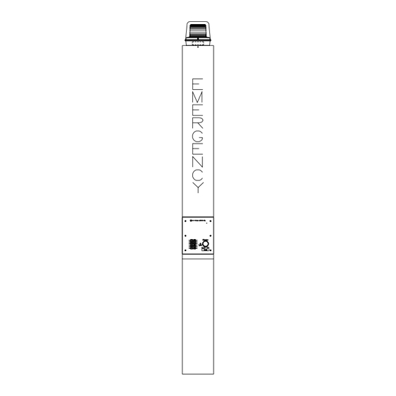
Model 234 Stanchion Assembly
Confidentiality Notice
This manual is provided solely as an installation, operation, and maintenance guide and contains sensitive
business and technical information that is confidential and proprietary to GAI-Tronics. GAI-Tronics
retains all intellectual property and other rights in or to the information contained herein, and such
information may only be used in connection with the operation of your GAI-Tronics product or system.
This manual may not be disclosed in any form, in whole or in part, directly or indirectly, to any third party.
Introduction
The complete emergency station is shipped in two stages. The Model 84504 Hardware Kit is usually
shipped in advance followed by the remaining assemblies (Model 84501, Model 84502, and Model
84503). In addition to this publication, refer to the following manuals to assist in properly installing a
complete station:
Pub. No.
Pub. 42004-284
Model 530FB Strobe with Dual Constant-On Lamps
Pub. 42004-352
Model 297-001 Flush-Mount Emergency Phone
Pub. 42004-351
Model 297-003 S.M.A.R.T. Flush-Mount Emergency Phone
Pub. 42004-352
Model 298-001 Flush-Mount Emergency Phone with Keypad
Pub. 42004-351
Model 298-003 S.M.A.R.T. Flush-Mount Emergency Phone with Keypad
The Model 234 Stanchion Assembly is designed to house a Model 298 or 297 Emergency Telephone and
a Model 530FB or 531A Beacon. This aesthetically-pleasing stanchion is over 9 feet tall, making it easily
located by potential users.
The beacon creates added noticeability to emergency telephone locations by providing a constant-on lamp
and a flashing strobe light is automatically engaged when the emergency button is pressed. The telephone
is also highly visible; a light mounted in the stanchion shines on the front panel of the telephone to
illuminate the phone for nighttime use.
GAI-Tronics enhanced emergency telephones are designed for isolated high-risk areas requiring
emergency communications equipment.
Emergency telephone users simply press the clearly labeled emergency push button for immediate
connection to a user-programmed central security telephone number.
GAI-Tronics Corporation P.O. Box 1060, Reading, PA 19607-1060 USA
610-777-1374
V
ISIT WWW
G A I - T R O N I C S ® C O R P O R A T I O N
A H U B B E L L C O M P A N Y
Emergency Phone Model
800-492-1212
.
-
.
GAI
TRONICS
COM FOR PRODUCT LITERATURE AND MANUALS
Fax: 610-796-5954
Pub. 42004-194H
Advertisement

Related Manuals for Hubbell GAI-TRONICS 234


Summary of Contents for Hubbell GAI-TRONICS 234
- Page 1 Pub. 42004-194H G A I - T R O N I C S ® C O R P O R A T I O N A H U B B E L L C O M P A N Y Model 234 Stanchion Assembly Confidentiality Notice This manual is provided solely as an installation, operation, and maintenance guide and contains sensitive...
- Page 2 Pub. 42004-194H 2 of 11 Model 234 Stanchion Assembly Page: Mounting A concrete pier is required to support the stanchion. GAI-Tronics provides the Model 84504 Hardware Kit to aid with the construction of this pier. We recommend using as a minimum, 3,000 psi grade concrete.
-
Page 3: Installation
Pub. 42004-194H 3 of 11 Model 234 Stanchion Assembly Page: Installation ATTENTION Installation should be performed by qualified personnel and only in accordance with the National Electrical Code and applicable local codes. The following information provides guidelines on the installation of various components of the emergency station. - Page 4 Pub. 42004-194H 4 of 11 Model 234 Stanchion Assembly Page: : The stanchion should not be mounted until the concrete has been allowed to cure for a minimum of 24 hours. Figure 4. Top View d:\standard ioms - current release\42004 instr. manuals\42004-194h.doc 09/05...
- Page 5 Pub. 42004-194H 5 of 11 Model 234 Stanchion Assembly Page: Model 84501 Stanchion Main Body Installation 1. If the concrete is not level, find the anchor rod at the highest point of the concrete, and screw one ¾-inch heavy hex nut 1- inches above the concrete surface (measuring to the top of the nut).
- Page 6 Pub. 42004-194H 6 of 11 Model 234 Stanchion Assembly Page: : A ¼-inch air gap must exist between the base of the stanchion and the top of the concrete pier. See Figure 6. This air gap must not be obstructed with soil, mulch, stone, etc. Figure 6.
- Page 7 Pub. 42004-194H 7 of 11 Model 234 Stanchion Assembly Page: Model 84503 Stanchion Panel Light Installation 1. Remove the two screws securing the bezel and lens to the stanchion panel light assembly. 2. Align the stanchion panel light assembly inside the stanchion as shown in Figure 7.
- Page 8 Pub. 42004-194H 8 of 11 Model 234 Stanchion Assembly Page: Model 530FB or 531A Beacon and Model 84502 Strobe Installation 1. Insert the beacon’s seven 15-foot wires through the stanchion’s threaded nipple, and allow the wires to extend to the base of the stanchion. See Figure 8. 2.
- Page 9 Pub. 42004-194H 9 of 11 Model 234 Stanchion Assembly Page: Emergency Telephone Installation 1. Separate the back box from the front panel of the telephone. Inside the back box is a parts envelope is containing eight 6-32 self-tapping flat head screws, six tamperproof screws, six washers, and a hole plug.
- Page 10 Pub. 42004-194H 10 of 11 Model 234 Stanchion Assembly Page: 9. Attach the telephone cable from the surge suppressor to TB1 on the telephone PCBA as shown in Figure 9. 10. Attach the strobe’s violet and orange control wires to TB2 on the telephone PCBA as shown in Figure Install the phone’s front panel using the six tamper-resistant screws and six washers provided.
-
Page 11: Specifications
Pub. 42004-194H 11 of 11 Model 234 Stanchion Assembly Page: Repairing Surface Damage to Powder Coated Stanchions Scratch Repair 1. Carefully sand the damaged area to clean and score the base metal, taking care to minimize any additional damage to the surrounding powder coating. 2. -
Page 12: Warranty
Warranty Equipment. GAI-Tronics warrants for a period of one (1) year from the date of shipment, that any GAI-Tronics equipment supplied hereunder shall be free of defects in material and workmanship, shall comply with the then-current product specifications and product literature, and if applicable, shall be fit for the purpose specified in the agreed upon quotation or proposal document.
Need help?
Do you have a question about the GAI-TRONICS 234 and is the answer not in the manual?
Questions and answers