Table of Contents
Advertisement
Electric Shock Hazard. All parts of recloser are energized.
Contact with in service recloser will cause death or severe injury.
Before contacting or servicing the equipment, or working on the electrical system, isolate and
ground the recloser from the electrical system. Verify recloser is de-energized by testing with
properly rated hot sticks and/or rubber gloves and volt meter.
8100 Churchill Avenue
Leeds, Alabama 35094
(205) 699-0840
www.hubbellpowersystems.com
NOTE: Hubbell has a policy of continuous product improvement.
We reserve the right to change design and specifications
without notice.
©Copyright 2015 Hubbell Incorporated
PSP8620311
Rev. E
Installation, Operation and
VERSA-TECH
Single-Phase Recloser
for Distribution Systems
DANGER
!
Maintenance Manual
I & VERSA-TECH
®
IMPORTANT!
Keep this manual readily
available for future reference.
LT
®
1
Advertisement
Table of Contents

Subscribe to Our Youtube Channel
Related Manuals for Hubbell VERSA-TECH LT


Summary of Contents for Hubbell VERSA-TECH LT
- Page 1 Leeds, Alabama 35094 (205) 699-0840 IMPORTANT! www.hubbellpowersystems.com Keep this manual readily NOTE: Hubbell has a policy of continuous product improvement. available for future reference. We reserve the right to change design and specifications without notice. ©Copyright 2015 Hubbell Incorporated PSP8620311...
- Page 2 Hubbell Power Systems, Inc. terms and conditions of sale constitute the entire obliga- tion of Hubbell Power Systems, Inc. The warranty in the terms and conditions of sale is the sole warranty of Hubbell Power Systems, Inc. Any statements in this document do not create new warranties or modify any existing warranty.
- Page 3 Contents Section Subject Page No. Section Subject Page No. 1 — Overview Connecting to WiFi Safety Information Remote Radio Power Ratings and Specifications Radio Operation Duty Cycle Windows XP Local Radio Drivers Installation Installation Alternatives Windows 7 Local Radio Drivers Installation Catalog Number Matrix Windows 8 Local Radio Drivers Installation Guide Dimensions - Pole/Structure Mount...
- Page 4 Contents Tables & Figures............Page Number Table 1-1 Duty Cycle ................. 6 Table 1-2 Recloser Catalog Number Matrix..........6 Table 2-1 Hardware Torque Specifications ..........9 Table 9-1 Trouble Shooting Guide............46 Figure 1-1 Pole/Structure Face Mounting ..........6 Figure 1-2 Crossarm Mounting ..............6 Figure 3-1 Components................10 Figure 4-1...
-
Page 5: Safety Information
1 — Overview Safety Information DANGER Handle position does not indicate de- DANGER energized recloser enclosure controls or circuit. All parts of recloser are energized. Contact with these components will cause severe personal injury, death, or property damage. Contact with components will cause severe personal injury, death, or property damage. -
Page 6: Table 1-1 Duty Cycle
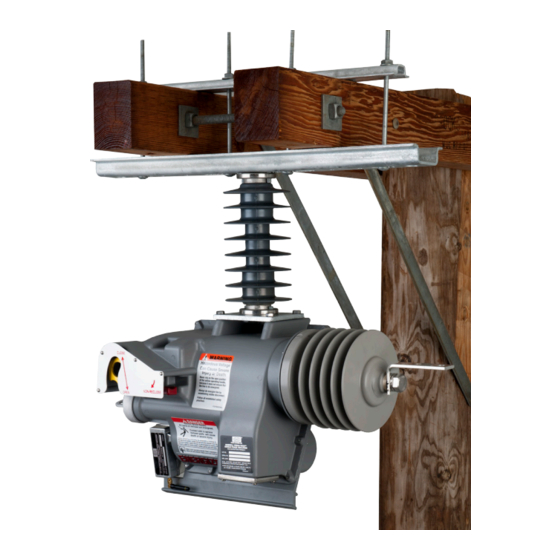
(Ex: 3 is 3 more for a total of 4) NOTE: For more information on the Versa-Tech II Single-Phase Recloser, please refer to Catalog 10EE on the Hubbell Power Systems website. Figure 1-2 Crossarm Mounting PSP8620311... -
Page 7: Dimensions - Pole/Structure Mount
1 — Overview Dimensions - Pole/Structure mounting MOUNTING HOLES FOR 5/8" (15mm) BOLTS 11" (27.9cm) CENTER TO CENTER NOMINAL. VACUUM INTERRUPTER Back View 11.0 17.1 12.4 29.5 Front View 2-HOLE NEMA PAD (STANDARD) TYPICAL 2-HOLE NEMA PAD (STANDARD) OPERATING LEVER TYPICAL NON-RECLOSE LEVER... -
Page 8: Dimensions - Crossarm Mount
1 — Overview Dimensions - Crossarm mounting 31.1 10.6 28.0 ADJUSTABLE 5-1/8" - 10-1/4" TYPICAL ADJUSTABLE 3" - 9-1/2" LEAKAGE DISTANCE - 39.4" 12.7 14.0 24.9 2-HOLE NEMA PAD (STANDARD) TYPICAL VACUUM INTERRUPTER LOCKOUT INDICATOR BEACON AND COUNTER NON-RECLOSE LEVER LOCKOUT INDICATOR BEACON AND COUNTER OPERATING LEVER... -
Page 9: Specifications
• Jumper Wire, 100/400 Amp minimum capacity (VTLT/VTI) • M3 Disconnect Switch (for appropriate Cat. No., see Catalog Section 14B) Hubbell Power Systems, Inc. Supplied Requirements All necessary components and hardware specific to the installation of the VERSA- TECH® recloser ordered are included. -
Page 10: Figure 3-1 Components
Inspection Unpacking Storage 1. Inspect the packaging for obvious 1. Locate the Hubbell USB Drive that is If the recloser is not going to be put into service shipping damage. enclosed with this manual. The USB immediately, re-pack all components in the... - Page 11 4 — Installation Installing the Optional Non- Reclose Hookstick Adapter The Non-Reclose (NR) Hookstick Adapter Kit is an adapter that can be attached to the NR handle on the Versa-Tech Recloser to allow for easier Clevis Pins operation with a hookstick. The addition of the adapter is not mandatory.
-
Page 12: Figure 4-7 Crossarm Mounting
Crossarm mounting, e.g., (PSC86)2X12XXX. Figure 4-8 Bypass Arrangement Hubbell Power Systems recommends the use of a by-pass switch in parallel with the recloser. This arrangement allows the unit to be easily taken out of the circuit for service, should the need arise. -
Page 13: Figure 4-9 Program/Installation Tag
Refer to sections 6 and 7 of this manual for control programming and operation. Installation Preparation Hubbell Versa-Tech Single Phase Recloser ® Complete this tag when unit is programmed and tie to the operating handle of the unit. 1. Program the unit with the desired... -
Page 14: Figure 4-10 Pole/Structure Mount Assembly Detail
4 — Installation Pole/Structure Surface Mounting 1. Refer to Figure 4-5 for assembly detail and Table 2-1 for torque specifications. • Assemble the insulator (1) to the rectangular steel adapter plate (2) using two 3/8" X 1" bolts and split lock washers (3) as shown. -
Page 15: Figure 4-13 Crossarm Assembly Detail
4 — Installation Crossarm Mounting This configuration is intended for application to a double crossarm structure. This is the preferred arrangement if three units are to be mounted. 1. Remove the four 3/8" X 5/8" bolts from top mounting flange (8) and use to fill the four holes on the cover (9). -
Page 16: Connections
4 — Installation Connections DANGER 1. Wire brush the jumper conductors and terminal pads. Electric Shock Hazard. All parts of recloser are energized. 2. Apply contact aid, such as CHANCE ZLN Contact with in service recloser will cause death or se- to the contact surfaces. -
Page 17: Overview
Refer to Figure 5-1 for the location of latching and holding force for the vacuum the Non-Reclosing Lever (red lever). The All Versa-Tech I and Versa-Tech LT interrupter in the closed position. A spring handle is shown in the normal or UP... -
Page 18: Figure 5-1 Feature Position
The lithium batteries provide the power for the flashing beacon. Versa-Tech I Reclosers with FW 3.xx and Versa-Tech LT Reclosers: The beacon will continue to flash every 3 seconds until the lineman closes the recloser or 1 hour has passed. After 1 hour, the flashing beacon will automatically shut OFF. -
Page 19: Figure 6-1 Connecting Local Radio
Versa-Tech I (FW 3.xx or 4.xx) desired, PC wireless card for connection through the WiFi and Versa-Tech LT through the internal wireless card on a PC and remote radio, local Digi/XBee radio with USB Type B serial the Versa-Tech Programmer software (UI version 4.50.15 or higher). -
Page 20: Psp8620311
6 — Control Programming Remote Radio Power When the VERSA-TECH Recloser is in service with a load current of 10 Amps or more, the attached remote radio is on and powered from ® the recloser's internal current transformers. If the recloser is not in service or the load current is less than 10 Amps, the radio is ON only for 10 minutes and must be powered from the recloser internal batteries. -
Page 21: Psp8620311
This time it is adding the USB port. 9. Repeat Steps 5 to 7 above. NOTE: Because Hubbell has a policy of continuous product improvement, we reserve the right to change design and specifications without notice. PSP8620311 Rev. E... -
Page 22: Psp8620311
“X” is the port number it is using. This number will be used during programming. NOTE: Refer to the "VTI Communication Troubleshooting Guide VT1-APR0013" which is available on the Hubbell Power Systems website for more detailed instructions on installing the local radio drivers. Before attempting to communicate with the recloser radios each time, be sure to: 1. -
Page 23: Psp8620311
6 — Control Programming Windows 7 Local Radio Drivers Installation Guide 1. Download the radio drivers from the Hubbell Power Systems website. Be sure to extract the files. 2. Connect the local radio to the computer with the provided USB cable. Windows will attempt to automatically install drivers using the found hardware wizard. -
Page 24: Psp8620311
6 — Control Programming Browse my computer for driver software 6. Select “ ” & select the Windows 7 64 bit drivers Next. location on the USB drive,. Click Cannot verify publisher Install anyway 7. Pop-up will say “ ,” choose “ ”;... -
Page 25: Psp8620311
NOTE: The installer must run twice. Once to install the radio driver itself and then again to install the USB Serial Port NOTE: Refer to the "VTI Communication Troubleshooting Guide VT1-APR0013" which is available on the Hubbell Power Systems website for more detailed instructions on installing the local radio drivers. PSP8620311... -
Page 26: Psp8620311
6 — Control Programming Windows 8 Local Radio Drivers Installation Guide To download and install the Digi/XBee 9XCite (USB, 232/485 module) local radio drivers for Windows 8, please visit the Digi International website. ® PSP8620311 Rev. E... -
Page 27: Psp8620311
6 — Control Programming Versa-Tech Programmer Settings Tab ® Figure 6-2 * For Versa-Tech I: Minimum trip is programmable from 30A-800A. ® For Versa-Tech LT: Minimum trip is programmable from 30A-200A. ® PSP8620311 Rev. E... -
Page 28: To Establish Communications
6 — Control Programming Connection Manual Connect Communications with the Versa-Tech Recloser can be established through the below two options. 1. Identify Device To establish communications through Manual Connect: 2. Manual Connect 1. Follow Step 1 - Step 3 from Identify Device section Identify device option scans for all possible reclosers available within the communication range with respect to the local device connected 2. -
Page 29: Psp8620311
6 — Control Programming Connecting to a Recloser with WiFi Radio 5. Once the WiFi Remote Radio is identified, the "Connect" button will be enabled. Click "Connect". In order to communicate with the WiFi radio, the Versa-Tech Single Phase Programmer v4.50.15 or higher will need to be used. To establish communication: 6. -
Page 30: Psp8620311
6 — Control Programming Settings Tab Programming Settings Operations to Lockout The Recloser Settings Tab appears when the Recloser The control can be set to 1, 2, 3, or 4 operations before the Programmer Software is loaded and opened. See Figure 6-2. At recloser goes to lockout. -
Page 31: Psp8620311
6 — Control Programming Time-Current Curve Selection The control can be set to utilize two different time current curves TCC1 and TCC2. TCC1 and TCC2 can be set separately to use one of 15 different time current curves. See Reference Bulletin TD10005E through TD100034E. Each of the 4 possible operations can be set to use either TCC1 or TCC2. -
Page 32: Psp8620311
6 — Control Programming Time Stamp The recloser has a built in time stamp circuit which records the time and date following each recloser operation. The time stamp on the recloser can be set in two ways. Every time the User Interface communicates with the unit, the Programmer generates a pop up question to auto sync the host computer's clock... -
Page 33: Psp8620311
6 — Control Programming Settings Tab To disconnect Click the “Disconnect” button. A “Rescan” for newly connected (within range) or different devices can now be performed by clicking the “Identify Device” button. Note the status indicators at the top of the form window. COM: Successful Communications RXD: Receive (data) NR: Non Reclose... -
Page 34: Psp8620311
6 — Control Programming Settings Tab Serial Number (S/N) Serial Number of the unit signifies the manufacturing date of the unit. It's based on the Julian date format that includes the last two digits of the year it was manufactured in, day of the year, the nth recloser manufactured on that day. -
Page 35: Psp8620311
6 — Control Programming Settings Tab Button Functions General Form Controls Read Settings From Recloser Extracts currently programmed settings values from the recloser control’s memory. Write Settings To Recloser Programs the recloser’s control with currently displayed settings values "Recloser Settings Profile". Recloser Settings Profile Load From Opens a window where previously stored settings can be retrieved from a known... -
Page 36: Psp8620311
6 — Control Programming Real Time Monitoring * For Versa-Tech I: RMS Current "Now" is 400A Max Figure 6-3 ® For Versa-Tech LT: RMS Current "Now" is 200A Max ® Instantaneous Current Monitoring The real time monitoring features are automatically updated following a successful connection. Now: It is the Root Mean Square current (RMS) calculated every one second. -
Page 37: Psp8620311
6 — Control Programming Events and Data Log Viewing Diagnostic Events and Data Log The recloser also has some built in diagnostic features, which can be read by selecting the Events and Data Log Tab as shown in Figure 6-4. This field will display the recloser operations count, the energy of interrupted faults, and the hourly log data field. Separately, the resettable operations counter can be reset and the data log erased by clicking the appropriate buttons. -
Page 38: Figure 6-5 Sequence Coordination Enabled On Four Operations And The Sc Lockout Option Checked
Figure 6-6: Sequence Coordination enabled on four operations and the SC Lockout option Unchecked (Versa-Tech I Reclosers with FW 4.xx). This would also be a representation for Versa-Tech I Reclosers with FW 3.xx and Versa-Tech LT Reclosers which do not have the option for SC Lockout. PSP8620311... -
Page 39: Figure 6-7 Time And Security Tab
Security Key to reset the password to the factory default password i.e., "password". For more information on your Security Key, please contact your local Hubbell representative or call customer service at (573) 682-5521. Figure 6-7 Time and Security Tab PSP8620311 Rev. -
Page 40: Figure 6-8 Scratchpad Tab
6 — Control Programming Scratchpad Viewing the Scratchpad The recloser has a convenient scratchpad built in to its non-volatile memory. The memory can store 256 characters of information in text form. The scratchpad is accessed by selecting the Scratchpad Tab as shown in Figure 6-6. The “Load From Recloser” button will show the current text stored in the recloser. -
Page 41: Psp8620311
- Allow the upgrade to continue to completion. - You should receive a “Successful, Device is operational. Press OK.” confirmation directly above the progress meter. NOTE: If upgrading to FW 4.xx, please refer to the Hubbell Power Systems website for the latest 4.xx Upgrade Instructions. -
Page 42: Figure 7-1 Recloser Attached To High Potential Test Set
7 — Testing High Potential Withstand WARNING Test Hazardous voltages are present during testing. Severe Applying AC 50/60 Hz voltage across the personal injury or death can occur from contact with open contacts of the recloser will test the recloser or high voltage transformer during tests. dielectric integrity of the vacuum interrupter. -
Page 43: Figure 7-2 Recloser Attached To High Current Test Set
7 — Testing Minimum Trip Current Test The minimum trip current test can be used to check programmed minimum trip settings as well as recloser control functionality. 1. Close the recloser contacts. 2. Connect a low voltage high current test set across the contacts by attaching one end of the test set to each of the 2-hole NEMA input pads (see Figure 7-2). -
Page 44: Figure 8-1 Battery Bayonet In The Recloser
The batteries are made of a very stable lithium chemistry, which is designed with a low self WARNING discharge with a shelf life of 10 years. Hubbell Power Systems is recommending that users High voltage electric contact hazard. replace the batteries on a maximum 8 year cycle Can cause severe injury or death. -
Page 45: Cleaning Instructions
8 — Maintenance Cleaning Instructions for Versa-Tech Recloser ® Battery Bayonet PSC8620068 1. Clean battery contact surfaces, recloser sleeve, and recloser battery contact surface with DeoxIT wipes per instructions on bag. Battery contact surfaces Recloser battery contact Recloser contact in base of tube sleeve 2. -
Page 46: Trouble Shooting
The following table presents possible symptoms, their possible cause(s) and likely corrective action(s). These do not cover all possible problems. For more detailed communication and troubleshooting guides, please visit the Hubbell Power Systems website. If you are unable to correct a problem using this trouble shooting guide, contact your local Hubbell representative or Customer Service at (573) 682-5521. -
Page 47: Return Kit Packaging Instructions
3. On the outer carton, apply the Class 9 label (provided in the return kit) on the same side of the carton imprinted with "LITHIUM BATTERIES PACKED WITH EQUIPMENT UN 3091". NOTE: Because Hubbell has a policy of continuous product improvement, we reserve the right to change design and specifications without notice. - Page 48 Notes PSP8620311 Rev. E...
- Page 49 Notes PSP8620311 Rev. E...
- Page 50 8100 Churchill Avenue Leeds, Alabama 35094 (205) 699-0840 www.hubbellpowersystems.com PSP8620311 PSP8620311 Rev. E Rev. E...
Need help?
Do you have a question about the VERSA-TECH LT and is the answer not in the manual?
Questions and answers