
Related Manuals for Omron MD-900


Summary of Contents for Omron MD-900
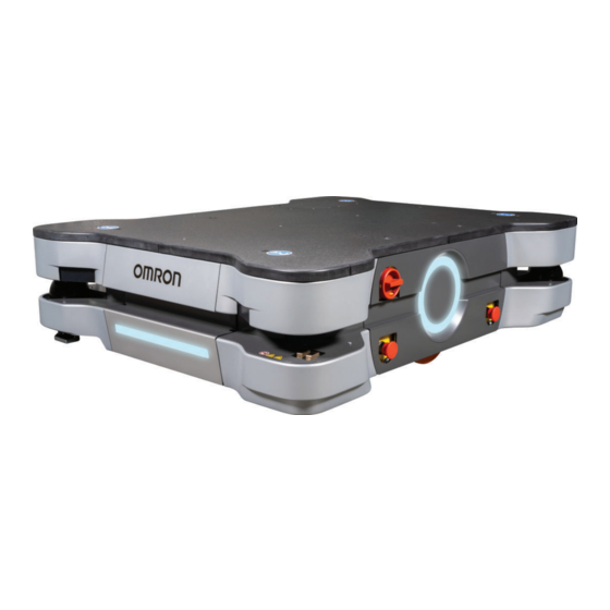
- Page 1 AMR (Autonomous Mobile Robot) MD-series Platform User's Manual MD-650 MD-900 I681-E-02...
- Page 2 Every precaution has been taken in the preparation of this manual. Nevertheless, OMRON assumes no responsibility for errors or omissions. Neither is any liability assumed for damages resulting from the use of the information contained in this publica- tion.
-
Page 3: Intended Audience
Thank you for purchasing the MD-series Autonomous Mobile Robot (referred to as AMR in this docu- ment). This manual is OMRON's original instructions describing the setup, operation, and user maintenance of the AMR. This manual does not describe all configuration steps that you perform using the software supplied with an AMR. -
Page 4: Manual Information
Manual Information Manual Information Page Structure The following page structure is used in this manual. 5 Installation Unpack This section provides details on how to unpack the Industrial Panel PC. 5-1-1 Unpack Procedure Check the package for damage. If there is any visible damage: •... - Page 5 Manual Information Precautions for Safe Use Precautions on what to do and what not to do to ensure safe usage of the product. Precautions for Correct Use Precautions on what to do and what not to do to ensure proper operation and performance. Additional Information Additional information to read as required.
- Page 6 Manual Information AMR (Autonomous Mobile Robot) MD-series Platform User's Manual (I681)
-
Page 7: Sections In This Manual
Sections in this Manual Sections in this Manual Overview Specifications Installation Operation Troubleshooting Maintenance Appendices Index AMR (Autonomous Mobile Robot) MD-series Platform User's Manual (I681) -
Page 8: Table Of Contents
CONTENTS CONTENTS Introduction ......................1 Intended Audience............................1 Units.................................1 Manual Information....................2 Page Structure..............................2 Special Information ............................2 Sections in this Manual ................... 5 Terms and Conditions Agreement................ 12 Warranty and Limitations of Liability ......................12 Application Considerations ..........................13 Disclaimers ..............................13 Safety Precautions....................15 Definition of Precautionary Information......................15 Symbols .................................15 Dangers .................................16... - Page 9 CONTENTS 1-2-13 Pendant .............................1-13 1-2-14 Speakers ...........................1-14 1-2-15 Charging Station ........................1-14 1-2-16 Input and Output Control ......................1-15 1-2-17 Wireless Antennas ........................1-15 1-2-18 Localization Sensors .........................1-15 Autonomous Navigation .....................1-17 Labels............................1-19 1-4-1 AMR Information Label ......................1-19 1-4-2 Docking Target Information Label .....................1-20 1-4-3 Power Supply Box Information Label ..................1-20 1-4-4...
- Page 10 CONTENTS 2-4-2 Battery Specifications........................2-15 2-4-3 HAPS Specifications .........................2-15 2-4-4 Charging Station Specifications ....................2-16 2-4-5 Operator Panel Screen ......................2-16 2-4-6 Onboard I/O ..........................2-16 2-4-7 USER PWR Connector ......................2-17 2-4-8 COMMS Connector ........................2-17 2-4-9 SCPU Connector........................2-17 2-4-10 AUX PLC Connector .........................2-18 2-4-11 LIGHTS Connector........................2-18 2-4-12 BUZZ Connector ........................2-18...
- Page 11 CONTENTS 3-13 Wireless Antenna Relocation Procedure................3-46 3-14 Operator Panel Relocation....................3-48 3-14-1 Relocation Considerations ......................3-48 3-14-2 Operator Panel Relocation Procedure ..................3-48 Section 4 Operation Payload Movement and Transfer..................4-3 AMR Start-up ..........................4-4 AMR Shut-down ........................4-5 AMR Controller LED Indicators ....................4-6 Workspace..........................4-7 4-5-1 Physical Barriers .........................4-9 4-5-2 Logical Barriers ...........................4-9...
- Page 12 CONTENTS 4-20 Overspeed Protection......................4-40 4-21 Light Discs and Optional Beacon States................4-41 4-21-1 Driving Straight..........................4-41 4-21-2 Turn Signal ..........................4-41 4-21-3 Emergency Stop........................4-41 4-21-4 Lost ............................4-41 4-21-5 Stopped .............................4-42 4-21-6 Stopped with Warning .......................4-42 4-21-7 Obstacle Detected / Protective Stop ..................4-42 4-21-8 Charging............................4-42 4-21-9 Booting ............................4-43...
- Page 13 CONTENTS Circuit Breakers and Fuses ....................5-13 5-9-1 Fuse Panel ..........................5-13 5-9-2 Circuit Breaker Panel ........................5-13 5-9-3 Battery Fuse ..........................5-14 5-10 Localization Problems......................5-15 5-11 Other AMR Problems......................5-16 Section 6 Maintenance Maintenance Introduction .....................6-2 AMR Lock-out Tag-out Procedure..................6-4 Inspection Intervals .......................6-5 Charging Station Lock-out Tag-out Procedure ..............6-6 Lifting the AMR ........................6-7 Mechanical Brake Inspection Procedure................6-9 Docking Target Charging Contacts Inspection..............6-10...
-
Page 14: Terms And Conditions Agreement
Omron’s exclusive warranty is that the Products will be free from defects in materials and work- manship for a period of twelve months from the date of sale by Omron (or such other period ex- pressed in writing by Omron). Omron disclaims all other warranties, expressed or implied. -
Page 15: Application Considerations
• Omron Companies shall not be responsible for the user’s programming of a programmable Product, or any consequence thereof. • Omron Companies shall not be responsible for the operation of the user accessible operating sys- tem (e.g. Windows, Linux), or any consequence thereof. - Page 16 Terms and Conditions Agreement Errors and Omissions Information presented by Omron Companies has been checked and is believed to be accurate; how- ever, no responsibility is assumed for clerical, typographical or proofreading errors or omissions. AMR (Autonomous Mobile Robot) MD-series Platform User's Manual (I681)
-
Page 17: Safety Precautions
Safety Precautions Safety Precautions Definition of Precautionary Information The following notation is used in this manual to provide precautions required to ensure safe usage of the AMR. The safety precautions that are provided are extremely important to safety. Always read and heed the information provided in all safety precautions. The following notation is used. -
Page 18: Dangers
Safety Precautions Dangers DANGER The AMR can cause serious injury to personnel or damage to itself or other equipment if it drives off of a ledge, such as a loading dock, or down stairs. Improper operation of the AMR on inclined floors that do not comply with the applicable operating specifications can result in the AMR tipping over, and consequently a serious personal injury. - Page 19 The assembly instructions shall then form part of the technical file for the final machine. Use only the specified tools, equipment, and OMRON-supplied spare parts to service and maintain the AMR according to the specified service intervals. Failure to do so could result in an unsafe operating state that might result in personal injury or damage to prop- erty.
- Page 20 AMR cannot stop reliably within the default zones. OMRON is not responsible for any risks in- curred by modifying safety zone sizes or other Safety Laser Scanner settings.
- Page 21 The AMR battery and the Charging Station outputs have high current. You must take ap- propriate precautions to avoid potential short circuit. Replace the battery only with an OMRON factory-supplied battery intended for use in the AMR. Do not use batteries intended for use in other OMRON AMR models.
- Page 22 If a payload or payload structure projects or overhangs the outer dimensions of the AMR, make the following considerations. • Contact your OMRON representative to change the size of the Safety Laser Scanners' zones. • Modify parameters to change the AMR's Width, LengthFront, LengthRear, and poten- tially its Radius.
- Page 23 Safety Precautions The AMR can cause serious injury to personnel or damage to itself if a dangerous area is not properly configured in the map and blocked with a physical barrier. An AMR can be unsafe if operated under environmental conditions other than those specified in this manual.
-
Page 24: Cautions
Safety Precautions Cybersecurity To maintain the security and reliability of the system, a robust cybersecurity defense pro- gram should be implemented, which may include some or all of the following: Anti-virus protection • Install the latest commercial-quality anti-virus software on the computer connected to the control system and keep the software and virus definitions up-to-date. - Page 25 Safety Precautions Any electrical charge that accumulates on the AMR skins does not have a path to ground, and therefore cannot discharge. This can be hazardous to electrostatic sensitive devices. Always keep electrostatic sensitive devices at least 30 cm away from the AMR skins.
-
Page 26: Precautions For Safe Use
It should be shipped and stored in the supplied packaging, which is designed to prevent damage from normal shock and vibration. • OMRON recommends storing and securing the Pendant when not in use to prevent an unauthorized person from operating the AMR. - Page 27 • In case of fire, use a type ABC or type BC dry chemical fire extinguisher. • Although the lasers used are Class 1/1M (eye-safe), OMRON recommends that you not look into the laser light. The maximum permissible exposure cannot be exceeded when viewing lasers with the naked eye.
- Page 28 • Never access the interior of the AMR while it is connected to the Docking Target. • Only use charging equipment and batteries supplied by OMRON. The charger shall only be used to charge an HD-1500 or MD-series AMR battery.
-
Page 29: Precautions For Correct Use
• Never expose the battery to water. • Rough or uneven floors can degrade the drive wheels, and shorten their life span. • Replacement of the differential drive train, casters, and wheels require an OMRON service engineer. Contact your local OMRON representative for more information. - Page 30 IP22 protection. • OMRON does not provide the protective coverings with the HAPS option. A protective covering needs to be installed when applying the magnetic tape to the floor to prevent damage from the AMR traffic.
- Page 31 • If the loaded AMR is too heavy to move manually, it is recommended that you seek additional help or remove the payload. • OMRON recommends that you train personnel on the safe use of the brake release operations and procedures for safely pushing an AMR.
-
Page 32: Regulations And Standards
Regulations and Standards Regulations and Standards Conformance to EU Directives The AMR complies with the following EU Directives. Directives • 2006/42/EC Machinery Directive • 2014/30/EU EMC Directive EN / IEC Standards The AMR system conforms to the following EN standards. •... -
Page 33: Conformance To Kc Certification
Regulations and Standards Conformance to KC Certification When you use this product in South Korea, observe the following precautions. This product meets the electromagnetic compatibility requirements for business use. AMR (Autonomous Mobile Robot) MD-series Platform User's Manual (I681) -
Page 34: Related Manuals
Related Manuals Related Manuals Use the following related manuals for reference. Manual Title Description Advanced Robotics Command Language Enterprise Describes how to use the Advanced Robotics Com- Manager Integration Guide (Cat. No. I618) mand Language (ARCL) a text-based, command line operating language Use ARCL to integrate a fleet of AMRs with an external automation system. -
Page 35: Glossary
Glossary Glossary Term / Abbreviation Description Ambient Operating Temperature The temperature range of the AMR's environment in which continued oper- ation is possible. This term is used to refer to the MD-series autonomous mobile robot. AMR Controller The AMR's main computing system that provides all navigational controls and application interfaces. - Page 36 Glossary Term / Abbreviation Description Fleet Two or more AMRs operating in the same workspace controlled by a single Fleet Manager. Fleet Manager The operational mode of the computing appliance (EM2100) that runs the FLOW Core software to control a fleet of AMRs. Fleet Operations Workspace A computing system that consists of software and hardware packages and (FLOW)
- Page 37 Glossary Term / Abbreviation Description Pendant A handheld, external input device for manually driving AMRs that is typical- ly used for map creation. Pickup A job segment where an AMR typically acquires a payload. PoE Network Switch Power over Ethernet technology allows network switches to transmit both power and data simultaneously through an Ethernet cable.
-
Page 38: Revision History
Revision History Revision History A manual revision code appears as a suffix to the catalog number on the front and back covers of the manual. I681-E-02 Cat. No. Revision code Revision code Date Revised content October 2023 Corrections and improvements. April 2023 Original production AMR (Autonomous Mobile Robot) MD-series Platform User's Manual (I681) -
Page 39: Overview
Overview This section provides general information about the AMR. Intended Use....................1-3 Features and Components ................1-6 1-2-1 Lasers......................1-6 1-2-2 Skins........................ 1-8 1-2-3 E-STOP Buttons ....................1-9 1-2-4 Operator Panel ....................1-9 1-2-5 Light Discs and Strips ................... 1-10 1-2-6 Charging Contacts.................. - Page 40 1 Overview 1-6-7 Mobile I/O Box....................1-29 1-6-8 High Accuracy Positioning System (HAPS) ..........1-29 1-6-9 Cell Alignment Positioning System..............1-29 1-6-10 Maintenance Port Extension Kit ..............1-30 1-6-11 Wireless Antenna Extension Kit ..............1-30 1-6-12 Operator Panel Relocation Kit............... 1-30 FLOW Core Software ...................
-
Page 41: Intended Use
OMRON does not provide the method of loading the payload on or off the AMR. It is the end user's responsibility to perform a complete task-based risk assessment in accordance with EN ISO 12100, and ensure safe transfer of the payload. - Page 42 1 Overview WARNING Dust, dirt, grease, and water (or other liquids) can affect wheel traction, as well as op- eration of the drive wheels. If the drive wheels slip, it can potentially affect operating duration, stopping distance, and navigation accuracy. The following actions are strictly prohibited and could result in injury or damage to the equipment.
- Page 43 1 Overview Precautions for Safe Use The following actions are required for safe use of the AMR. • Review and understand the safety protections associated with your specific application and environment. • Make sure that the environment is suitable for safe operation of the AMR. •...
-
Page 44: Features And Components
1 Overview Features and Components This section provides an overview of the basic features and components of the AMR. Item Description Item Description Safety Laser Scanner Light Disc Low Laser Charging Contacts Front / Rear Skin User Connections area / Cover Side Skin Payload Mounting Surface / Top Plate... - Page 45 Precautions for Safe Use • Although the lasers used are Class 1/1M (eye-safe), OMRON recommends that you not look into the laser light. The maximum permissible exposure cannot be exceeded when viewing lasers with the naked eye.
-
Page 46: Skins
1 Overview Low Lasers Two Low Lasers detect obstacles below the scanning plane of the Safety Laser Scanner, such as an empty pallet or fork truck blades, which are too low for the Safety Laser Scanner's detection plane. The Low Lasers are positioned near the floor and can detect objects that are at least 60.5 mm tall. The Low Lasers also detect obstacles that might be significantly wider near the floor, such as a col- umn base, while the Safety Laser Scanners might detect only the upper, narrow portion of the column. -
Page 47: E-Stop Buttons
1 Overview 1-2-3 E-STOP Buttons There are five E-STOP buttons located on the AMR. One button is located on the Operator panel and there are two buttons located on each side of the AMR. The Pendant also has an integrated E-STOP button. Additional Information Additional E-STOP buttons can be added to the system when required. -
Page 48: Light Discs And Strips
1 Overview Brake Release Button A brake release button is provided in the event of an emergency or abnormal situation where the AMR needs to be manually moved. Emergency Stop Button The emergency stop button is connected to the safety circuit and has the same function as all other emergency stop buttons on the AMR. -
Page 49: User Connections Area
1 Overview A red LED charge light illuminates when power is present at the charging contacts. Charging Contacts 1-2-7 User Connections Area Connections for power, communications, safety devices, inputs, outputs, and other optional items are provided in the User Connections area. These connections are typically used for powering and con- trolling a payload structure. -
Page 50: Payload Mounting Surface
This arrangement allows the AMR to maintain contact with the floor over uneven areas or bumps. Precautions for Correct Use Replacement of the differential drive train, casters, and wheels require an OMRON service en- gineer. Contact your local OMRON representative for more information. -
Page 51: Battery
1 Overview 1-2-12 Battery A rechargeable lithium ion battery provides power to the entire AMR and any accessories. The battery can be automatically recharged while in the AMR, or it can be removed and charged sepa- rately. 1-2-13 Pendant Connect a Pendant to manually drive the AMR. A pendant is typically used when generating a map of the workspace. -
Page 52: Speakers
1 Overview 1-2-14 Speakers Two speakers can be used as a means to audibly notify personnel of an approaching AMR. Speech and sound tasks control the speakers' audio as the AMR navigates the workspace. Refer to Fleet Operations Workspace Core User's Manual (Cat. No. I635) for more information. The locations of the speakers are provided below. -
Page 53: Input And Output Control
1 Overview Additional Information • The automated Charging Station can either manually or automatically charge the AMR bat- tery according to the charging parameters set in MobilePlanner. • If you have more than one AMR that use a single Docking Target, make sure that your map contains features such as parking spaces or queuing lanes to accommodate AMRs that are approaching and leaving the charging area. - Page 54 1 Overview rotation. There are also sensors on each motor that are used by the safety system to collect redundant speed information. 1-16 AMR (Autonomous Mobile Robot) MD-series Platform User's Manual (I681)
-
Page 55: Autonomous Navigation
1 Overview Autonomous Navigation The AMR combines hardware and mobile-robotics software to provide an adaptive, mobile platform to transport a payload. It is equipped with a Natural Feature Navigation system which enables the AMR to navigate and perform its basic functions independently and without the need for facility modification. After it scans physical features in its environment, the AMR navigates safely and autonomously to any accessible destination. - Page 56 Additional Information The AMR is capable of navigating autonomously while traveling in reverse, but special applica- tion-specific considerations and adjustments must be made. Contact your local OMRON repre- sentative for more information. 1-18 AMR (Autonomous Mobile Robot) MD-series Platform User's Manual (I681)
-
Page 57: Labels
(LiFePO4) Batteries Caution: Risk of Fire or Explosion. www.ia.omron.com Only replace with identical battery. Designed in California 4225 Hacienda Drive, Pleasanton, CA 94588 USA Omron Robo cs & Safety Technologies, Inc. Assembled in California Item Name Description Part Number The AMR part number is provided. -
Page 58: Docking Target Information Label
1 Overview 1-4-2 Docking Target Information Label The Docking Target information label is described below. The following example may differ slightly from your product's label. Item Name Description Part Number The Docking Target part number is provided. Product Type The product type is provided. Docking Target Information General information about the Docking Target is provided. -
Page 59: Battery Information Label
Caution: Use only to char ge MD or HD Series Battery Use only with MD or HD Robot www.ia.omron.com 4225 Hacienda Drive, Pleasanton, CA 94588 USA Omron Robotics & Safety Techno logies, Inc. COO: US Item Name Description Part Number The Power Supply Box part number is provided. -
Page 60: Amr Safety And Warning Label Locations
1 Overview Item Name Description Product Origin Information Product origin information is provided. Alerts, Compliance, and Desig- General alerts, compliance, and battery designation informa- nation tion is provided. Serial Number 1-4-5 AMR Safety and Warning Label Locations Use the following information to understand all safety and warning label locations on the AMR. CAUTION WARNING Risk of Fire or Explosion. -
Page 61: Power Supply Box Safety And Warning Label Locations
1 Overview 1-4-6 Power Supply Box Safety and Warning Label Locations Use the following information to understand all safety and warning label locations on the Power Supply Box. 1-4-7 Docking Target Safety and Warning Label Locations Use the following information to understand all safety and warning label locations on the Docking Tar- get. - Page 62 1 Overview Symbol Meaning Do not step or stand on this surface Electric shock hazard Heat hazard 1-24 AMR (Autonomous Mobile Robot) MD-series Platform User's Manual (I681)
-
Page 63: Part Numbers
AMR and charging component part numbers are provided in the table below. Refer to A-1 Parts List on page A-2 for other replacement and spare components. Item Part Number MD-650 AMR 73000-060 MD-900 AMR 73000-090 Power Supply Box 73990-000 Docking Target 68910-000... -
Page 64: Optional Items
1 Overview Optional Items Information about optional items is provided in this section. 1-6-1 Fleet Manager To manage and administer multiple AMRs in the same workspace, you must use a Fleet Manager run- ning the Fleet Operations Workspace (FLOW) software. The Fleet Manager is a computing device with a processor capable of running the Fleet Operations Workspace Core suite. -
Page 65: Additional E-Stop Buttons
1 Overview Precautions for Correct Use • Using the Fleet Manager or map features is not a substitute for physical methods of prevent- ing collisions, such as interlocked gateways or barriers. It is the user's responsibility to pro- vide a physical method of preventing collisions where necessary. •... -
Page 66: Additional Warning Buzzers
Connections Area on page 3-19 for more information. Additional Information You can optionally supply an LED signal tower which includes a built-in warning buzzer, or a dedicated warning buzzer. Contact your OMRON representative for more information on the available options. 1-6-5... -
Page 67: Spare Battery
• If it is not possible to prevent some interference between the payload and the Side Lasers' sensing plane, contact your local OMRON representative for advanced configuration settings. • Laser lenses can easily get scratched and damaged. Care must be taken to prevent scratch- ing the laser lens during any maintenance or installation procedures. -
Page 68: Maintenance Port Extension Kit
This feature also enables smoother and quicker loading and unloading of material, contributing to a shorter cycle time. The CAPS license part number is 20271-805. Contact your local OMRON representative for more in- formation. Additional Information Refer to the Fleet Operations Workspace Core User's Manual (Cat. -
Page 69: Flow Core Software
1 Overview FLOW Core Software The FLOW (Fleet Operations Workspace) Core software package consists of different software com- ponents that provide specific functionality during AMR configuration and operation. The information in this section provides an overview of the different FLOW Core software components, their functions, and interactions within the AMR system. -
Page 70: Fleet Management Software
• View alerts from AMRs. 1-7-2 Fleet Management Software Fleet Management software runs on the Fleet Manager hardware. It provides the following general functionality for a fleet of OMRON AMRs. 1-32 AMR (Autonomous Mobile Robot) MD-series Platform User's Manual (I681) -
Page 71: Setnetgo Software
Refer to the Mobile I/O Box User's Manual (Cat. No. I677) for more information. Integration Toolkit (ITK) Package The Integration Toolkit is OMRON’s interface application that enables integration between the Fleet Manager and the end user’s client application, manufacturing execution system (MES), or warehouse management system (WMS). -
Page 72: Mobilefirmware
1 Overview This integration layer facilitates autonomous control for a fleet of AMRs using standard communication methods including REST and SQL. The Integration Toolkit facilitates queuing and monitoring of all AMR job types such as pickup, drop-off, and multi-segment. Additional Information Refer to the Fleet Operation Workspace Core Integration Toolkit User’s Manual (Cat. -
Page 73: Fleet Simulator Software
Fleet Simulator Software Fleet Simulator software runs on the Fleet Manager hardware. It provides the following general func- tionality for a simulated Fleet of OMRON AMRs. • Assess impact of map changes, scaling, route changes, and new software features. • Simulate up to 10 AMRs in up to three separate Fleets. -
Page 74: Payload Considerations
1 Overview Payload Considerations This section describes considerations and requirements for AMR payloads. A payload is considered as any item(s) that are placed on the AMR for the purposes of securing, transporting, and transferring some object. A payload structure is typically required to secure an object during transport. -
Page 75: Payload Structures
If a payload or payload structure projects or overhangs the outer dimensions of the AMR, make the following considerations. • Contact your OMRON representative to change the size of the Safety Laser Scan- ners' safety zones. • Modify parameters to change the AMR's Width, LengthFront, LengthRear, and po- tentially its Radius. -
Page 76: Power Consumption
1 Overview Light Discs and Light Strips You must ensure that the payload does not block the light discs, or front or back light strips as they provide visual indication of the AMR movement. Access to User Connections Area Connectors such as the MAINT port may need to be readily accessible without removing the pay- load structure. -
Page 77: Coordinate System
1 Overview Coordinate System AMRs use the X, Y, Z, and Theta coordinate system displayed in the figure below. This information is relevant for some of the procedures used in this manual, such as identifying which are the left or right sides of the AMR. - Page 78 1 Overview 1-40 AMR (Autonomous Mobile Robot) MD-series Platform User's Manual (I681)
-
Page 79: Specifications
Specifications This section provides specifications of the AMR and other associated items. Performance Specifications ................2-2 Physical Specifications ................. 2-3 2-2-1 Dimensions...................... 2-3 2-2-2 Center of Rotation ................... 2-6 2-2-3 AMR Center of Gravity ..................2-7 2-2-4 Payload Center of Gravity ................2-7 2-2-5 Weights ...................... -
Page 80: Performance Specifications
2 Specifications Performance Specifications Performance specifications for the AMR are provided below. Item Specification AMR Model MD-650 MD-900 Maximum payload capacity 650 kg 900 kg Run time Full payload: approximately 8 hours No payload: approximately 10 hours Swing radius 729 mm... -
Page 81: Physical Specifications
2 Specifications Physical Specifications Physical specification of the AMR and other items are provided below. 2-2-1 Dimensions Dimensional specifications are provided in the following sections. Overall Dimensions The overall dimensions of the AMR are provided below. 1194 Power Supply Box Dimensions Physical dimensions of the Power Supply Box are provided below. - Page 82 2 Specifications Docking Target Dimensions Physical dimensions of the Docking Target are provided below. 1315 255 100 1256 1306 325 297 Battery Dimensions Physical dimensions of the battery are provided below. Operator Panel Dimensions Physical Dimensions of the Operator Panel are provided below. AMR (Autonomous Mobile Robot) MD-series Platform User's Manual (I681)
- Page 83 2 Specifications 40° 110 96 10° 4 X Countersink M5 Flat Head Screws 137.5 137.5 11.4 2 X Countersink M5 Flat Head Screws 4 X Threaded Stud M4 X 0.7 X 10 Tall 17.5 20.3 Side Laser Dimensions Physical dimensions of the Side Laser are provided below. 2X M5 Screws 37.5 91.5...
-
Page 84: Center Of Rotation
2 Specifications Payload Structure Mounting Point Dimensions Payload structure mounting point dimensions are provided below. Refer to 3-6-1 Payload Structure Mounting Points on page 3-27 for more information. 12X M6 x 1.0 8X M16 x 2.0 AMR Charging Position Dimensions The AMR charging position dimensions are provided below. -
Page 85: Amr Center Of Gravity
AMR traverses irregularities in the floor. MD-650 has a maximum payload of 650 kg, while MD-900 has a maximum payload of 900 kg. This includes the payload structure and any load carried by that structure. The center of gravity of the com- bined mass of the payload structure, including all onboard tooling and loads being transported, must be within the specified limits. - Page 86 2 Specifications the end user's responsibility to ensure that the AMR is configured for safe operation under these op- erating conditions. • If the payload is tall and also has substantial weight, consider the effect on the AMR's center of gravity.
- Page 87 2 Specifications MD-650 Front View 2.50 2.00 1.50 1.00 0.50 0.00 -0.40 -0.20 0.00 0.40 0.20 130 Kg Side View 130 Kg Front View (slice) 390 Kg 390/650 Kg Front View (slice) 650 Kg AMR (Autonomous Mobile Robot) MD-series Platform User's Manual (I681)
- Page 88 -0.60 -0.40 -0.20 0.00 0.40 0.20 0.60 130 Kg Side View 390 Kg 130 Kg Front View (slice) 390/650 Kg Front View (slice) 650 Kg MD-900 Top View 0.40 0.20 0.00 -0.20 -0.40 -0.60 0.60 -0.40 -0.20 0.20 0.40 0.00...
- Page 89 2 Specifications MD-900 Front View 1.60 1.40 1.20 1.00 0.80 0.60 0.40 0.20 0.00 -0.40 -0.20 0.20 0.40 0.00 180 Kg 540 Kg 900 Kg 2-11 AMR (Autonomous Mobile Robot) MD-series Platform User's Manual (I681)
-
Page 90: Weights
2 Specifications MD-900 Side View 1.60 1.40 1.20 1.00 0.80 0.60 0.40 0.20 0.00 -0.40 -0.20 0.00 0.20 0.40 0.60 -0.60 180 Kg Side View 540 Kg 180/540/900 Kg Front View (slice) 900 Kg 2-2-5 Weights Weights are provided in the table below. -
Page 91: Environmental Specifications
20 mm gaps may be traversed at any speed. Traversing a 30 mm gap must occur at speeds below 2000 mm/s for MD-650 and below 1500 mm/s for MD-900. 2-13 AMR (Autonomous Mobile Robot) MD-series Platform User's Manual (I681) -
Page 92: Charging Station Environmental Specifications
2 Specifications The AMR is supplied with open holes in the Top Plate for payload mounting. Ensure these holes are either covered or plugged using the provided Top Plate Seal Kit (part number 24861-000) to maintain IP22 protection. 2-3-2 Charging Station Environmental Specifications Environmental specifications for the Power Supply Box and Docking Target are provided below. -
Page 93: Other Specifications
2 Specifications Other Specifications Other specifications are provided in the following sections. 2-4-1 Laser Specifications Specifications for the lasers are provided below. Item Specification Safety Laser Scanner Sensing Horizontal plane 175 mm from floor surface to a range of 40 m. Plane Safety Laser Scanning Class Class 1M in accordance with the following standards:... -
Page 94: Charging Station Specifications
2 Specifications Item Specification Magnetic tape width x length 25 mm x 300 mm Magnetic tape orientation South up (markers north up) Separation from tape 20 to 30 mm Protective covering tape (recommended) Mighty Line Safety Floor Tape, Solid (102 mm width) 2-4-4 Charging Station Specifications Specifications for the Charging Station are provided below. -
Page 95: User Pwr Connector
2 Specifications 2-4-7 USER PWR Connector Electrical and other specifications for the USER PWR connector are provided below. Item Specification AMR connector Anderson Power Pole SBS-50BLU User-supplied mating connector User-supplied connector pins Anderson Power Pole: • 16 mm wire size: 1339G2 •... -
Page 96: Aux Plc Connector
2 Specifications Item Specification Safety output current 500 mA Recommended user-supplied Molex components are provided. Other compatible options are available. Re- fer to Molex for more information. 2-4-10 AUX PLC Connector Electrical and other specifications for the AUX PLC connector are provided below. Item Specification AMR Connector... -
Page 97: Reg Pwr Connector
Specification Drive wheels Steel wheels with ESD tread Drive wheel dimensions 200 mm diameter x 65 mm width (MD-650); 160 mm diameter x 65 mm width (MD-900) Drive wheel motor 1000 W PMS servo motor Casters Cast iron wheels with polyurethane tread... -
Page 98: Safety Function Performance Levels
2 Specifications Description Specification Brakes 125 N⋅m holding torque Steering Differential 2-4-16 Safety Function Performance Levels The Performance Level (PL) calculation for safety functions of the AMR is based on the ISO 13849 standard. PL evaluation has been performed for the AMR including the pendant. The PL achieved and the Probability of Dangerous Failure per Hour (PFHd) are calculated using SIS- TEMA as per ISO 13849-1 for the following safety functions. - Page 99 2 Specifications Safety Reset Safety Function Description Category PFHd Stop Type Type Emergency stop Emergency Manual User-supplied E-STOP To be 5.79 x 10 Stop Reset button(s) can be attached deter- connection(s) to the SCPU connection mined located in the User Con- by the nections area.
-
Page 100: Stopping Distance And Time
Reset overspeed and speed in- consistency. The AMR lin- ear speed is limited to 2200 (MD-650) and 1800 (MD-900) mm/s (both for- ward and backward). If the calculated speed ex- ceeds this speed limit, the AMR protective stop is triggered. - Page 101 Test Assumptions: • Robot payload: 650 kg (MD-650), 900 kg (MD-900) • Velocities tested (AMR maximum): 100 to 2200 mm/s (MD-650), 100 to 1800 mm/s (MD-900) • Floor friction: 0.63 dynamic and 0.76 static coefficient of friction • Specified Overall Floor Flatness (SOFF): 25 (Moderately Flat) •...
-
Page 102: Wireless Specifications
2 Specifications MD-900 Stopping Distance 1000 Velocity (mm/s) MD-900 Stopping Time 1.75 1.50 1.25 1.00 0.75 0.50 0.25 0.00 Velocity (mm/s) 2-4-18 Wireless Specifications Wireless network specifications for the AMR are provided below. Item Description Signal Strength The minimum required signal strength is -60 dBm. - Page 103 2 Specifications Item Specification Maximum obstacle height above ground for detection 175 mm Minimum obstacle width for detection at maximum range 70 mm Minimum obstacle avoidance reaction time 250 ms Optional side lasers can be used to change the detection height of the robot. Refer to 1-6-5 Side Lasers on page 1-28 for more information.
- Page 104 2 Specifications 2-26 AMR (Autonomous Mobile Robot) MD-series Platform User's Manual (I681)
- Page 105 Installation This section describes how to install and configure the AMR for operation. Installation Introduction ................3-3 Charging Station Installation ................ 3-4 3-2-1 Repositioning the Docking Target Power Connector........3-5 3-2-2 Mechanical Connections ................. 3-5 3-2-3 Charging Paddle Adjustments................. 3-6 3-2-4 Electrical Connections..................
- Page 106 3 Installation 3-12 Maintenance Port Extension Procedure ............ 3-44 3-13 Wireless Antenna Relocation Procedure ........... 3-46 3-14 Operator Panel Relocation ................3-48 3-14-1 Relocation Considerations ................3-48 3-14-2 Operator Panel Relocation Procedure ............3-48 AMR (Autonomous Mobile Robot) MD-series Platform User's Manual (I681)
-
Page 107: Installation Introduction
3 Installation Installation Introduction The general AMR installation steps are provided below. WARNING • Use safe lifting practices when moving the heavy objects such as the Power Supply Box, Battery, Docking Target, and AMR. • The Charging Station, battery, and AMR transfer high electric power and contain hazardous voltages. -
Page 108: Charging Station Installation
3 Installation Charging Station Installation Make the following considerations before installing the Charging Station. • Install the Charging Station on a flat and level floor, in a location that is kept clear and is easily ac- cessible to AMRs. • Install the Docking Target away from forklift traffic or high traffic areas. This will prevent collisions between the docked AMRs and other operating vehicles in the area. -
Page 109: Repositioning The Docking Target Power Connector
3 Installation Precautions for Correct Use Vertical orientation of the Power Supply Box allows for heat dissipation, which prevents over- heating and possible fire danger. Horizontal installation of the Power Supply Box is not allowed. 3-2-1 Repositioning the Docking Target Power Connector The Docking Target power connector allows for horizontal and vertical connection of the power cord to suit your mounting location requirements. -
Page 110: Charging Paddle Adjustments
If the screw is turned beyond seven full rotations, correct charging paddle adjustment may not be possible and OMRON support may be necessary. • After making adjustments to the charging paddle, carefully observe the AMR as it approaches the Docking Target and be prepared to press an E-STOP button if alignment is not correct. -
Page 111: Electrical Connections
3 Installation Angle Vertical Adjustment Height Adjustment Use a 6 mm hex key to adjust the charging paddle in the following manner. • Turn the vertical height adjustment screw clockwise to increase the height of the charging paddle and counterclockwise to decrease the height of the charging paddle. •... - Page 112 3 Installation WARNING Improper installation or wiring misconfiguration of the Power Supply Box could result in electrical shock hazard. You must ensure the safe and proper installation of the Power Supply box in accordance with the applicable rules and regulations, and by qualified personnel.
- Page 113 3 Installation Wye Configuration User-supplied Connections Jumper Arrangement To Door Ground Point (A) Disconnect Switch (B) Terminal Strip (C) Circuit Breakers (D) Ground Bar AMR (Autonomous Mobile Robot) MD-series Platform User's Manual (I681)
-
Page 114: Commissioning Procedure
3 Installation Delta Configuration User-supplied Connections Delta Jumper Arrangement To Door Ground Point (A) Disconnect Switch (B) Terminal Strip (C) Circuit Breakers (D) Ground Bar 3-2-5 Commissioning Procedure Use the following procedure to commission the Power Supply Box. Prepare the facility AC supply and its disconnect switch. Make sure that the facility power is in the OFF state. - Page 115 3 Installation Turn the Power Supply Box Main Disconnect Switch located on the electrical access panel to ON position (vertical). This will allow the facility AC power to energize the Power Supply Box. Confirm that the blue LED on the Power Supply Box turns ON to complete this procedure. 3-11 AMR (Autonomous Mobile Robot) MD-series Platform User's Manual (I681)
-
Page 116: Battery Removal And Installation
3 Installation Battery Removal and Installation Removal or installation of the battery must be performed by persons who have read and understood this manual. Before you begin, press an E-STOP button, turn the AMR OFF, and then place the Main Disconnect Switch in the OFF position. -
Page 117: Battery Removal Procedure
3 Installation 3-3-1 Battery Removal Procedure Use the following procedure to remove the battery from the AMR. The following tools are required for this procedure. • T30 star bit • Torque wrench Turn the AMR OFF. Place the Main Disconnect Switch in the OFF position. Remove the Front Skin and then disconnect all cables. -
Page 118: Battery Installation Procedure
3 Installation Use the handle to pull the battery out of the battery compartment. Do not drop the battery while removing it. Align the battery compartment cover over the screws and slide it down to fit it in place. Tighten the four M6 screws to a torque of 9 N-m. Replace the Front Skin to complete this procedure. - Page 119 3 Installation Slide up the battery compartment cover and remove it from the AMR. Align the battery in the battery compartment and then slide it towards the rear of the AMR. Push the battery back until it stops. Alignment tabs keep the battery in position as it mates with the internal power connector.
-
Page 120: Network Connections
3 Installation Network Connections Wireless and wired networks are available on the AMR. The wired network is typically used for initial configuration and troubleshooting. The wireless network is typically used during normal operation and can also be used for maintenance and troubleshooting. Use the information in this section to configure the network settings of the AMR. -
Page 121: Wireless Connection
3 Installation DHCP is used by default. If a static IP is preferred, set the range between 172.16.0.100 to 172.16.0.149. Verify the settings by opening a browser window and accessing https://172.16.0.215. If the set- tings are correct, this will display the SetNetGo web interface and complete this procedure. 3-4-3 Wireless Connection A wireless connection is required when the AMR is operating in a workspace with other AMRs. - Page 122 3 Installation Item Details Authentication OPEN (not recom- Method mended) WPA2-PSK Key is either: Passphrase (8-63 ASCII only) Raw Hex (64 Hex-on- WPA-PSK Key is either: Passphrase (8-63 ASCII only) Raw Hex (64 Hex-on- • PEAP-MSCHAPv2 Username: • Password: • Private key: •...
-
Page 123: Electrical Connections
3 Installation Electrical Connections Use the following information to understand the AMR's electrical connections. 3-5-1 User Connections Area The following information describes items in the User Connections Area. These items are typically used when integrating a payload system with the AMR. Precautions for Correct Use Do not place additional components in the User Connections area. - Page 124 3 Installation MAINT The MAINT Ethernet port is available for configuration and troubleshooting with a PC that is directly connected with a pass-through or cross-over CAT5 (or better) Ethernet cable. The permanent Maintenance Ethernet Port IP address is 172.16.0.215. Refer to 3-4 Network Con- nections on page 3-16 and 4-14 Maintenance Ethernet Port on page 4-31 for more information.
- Page 125 3 Installation Precautions for Correct Use You must attach either a jumper or some other safety-rated devices (typically E-STOP buttons) to the SCPU connector in order for the AMR to function. The following figure shows the pin arrangements for the SCPU connector on the AMR. PIN 1 PIN 9 PIN 10...
- Page 126 3 Installation Pin Number Item Description Protective stop channel 2 input Dual-channel protective stop circuit input. Monitored for simultaneous switching within 500 Refer to 4-19 Protective Stops on page 4-38 for more information. Ground 24 VDC For use with alternative safety zone / protective stop circuits.
- Page 127 3 Installation SCPU Connector PIN 10 PIN 11 User-supplied Emergency Stop PIN 2 Devices PIN 1 PIN 6 PIN 7 User-supplied + 24 VDC Protective Stop Devices PIN 4 PIN 13 PIN 15 PIN 16 + 24 VDC Alternate Safety Zone PIN 8 PIN 17 PIN 9...
- Page 128 3 Installation 24 VDC Ground LIGHTS The LIGHTS connector in the User Connections area provides outputs for user-supplied signaling devices such as signal beacons or buzzers. Use the information below to understand all LIGHTS connections. The following figure shows the pin arrangements for the LIGHTS connector on the AMR. PIN 4 PIN 6 PIN 3...
- Page 129 3 Installation REG PWR The REG PWR connector in the User Connections area provides regulated 24 VDC power and is typically used for payload structure control devices. Use the information below to understand all REG PWR connections. Ground 24 VDC Ground 24 VDC ...
- Page 130 3 Installation Additional Information • Refer to AUX PLC on page 3-23 for more information. • Refer to the NX-series NX102 CPU Unit Hardware User's Manual (Cat. No. W593) • Refer to the NX-series Digital I/O Unit User's Manual (Cat. No. W521) 3-26 AMR (Autonomous Mobile Robot) MD-series Platform User's Manual (I681)
-
Page 131: Attaching The Payload
3 Installation Attaching the Payload Use the information in this section to understand design considerations and other factors for attaching a payload to the AMR. Precautions for Safe Use You must perform a complete risk assessment for your payload design and the intended use of the AMR prior to its operation. -
Page 132: Overhanging Payloads
Overhanging Payloads Increasing the AMR's physical length or width by adding an overhanging payload requires that you in- crease the dimension of the AMR's safety zones. Contact your OMRON representative for more infor- mation on modifying the safety zones. Refer to 4-25-2 Alternate Safety Laser Scanner Zones on page 4-73 for more information. -
Page 133: Haps Installation And Configuration
3 Installation HAPS Installation and Configuration The following sections provide information about HAPS sensor installation and other configuration de- tails. 3-7-1 Front HAPS Sensor Installation Use the following procedure to install a HAPS sensor on the front of the AMR. Make the following considerations before attempting this procedure. -
Page 134: Rear Haps Sensor Installation
3 Installation Place the HAPS sensor in the following position and then insert two M3 x 8 screws using a T10 star bit. Apply a torque of 1 N-m. Plug the M12 connector on the cable into the HAPS sensor. Replace the front and right skins to complete this procedure. - Page 135 3 Installation • The AMR must be turned OFF and the disconnect switch must be in the OFF position. The following components are required for this procedure (included with double sensor HAPS kit 73925-020). • Rear HAPS sensor. • M12 to Mini FIt Jr. cable (2 m). •...
-
Page 136: Tape And Marker Application
Markers (short sections of the tape) are used to signal the AMR where to stop. Precautions for Correct Use • OMRON does not provide the protective coverings with the HAPS option. A protective cover- ing needs to be installed when applying the magnetic tape to the floor to prevent damage from the AMR traffic. -
Page 137: Software Configuration
3 Installation The AMR will stop with the front sensor at the front end of the marker. Note the model-dependent loca- tions of the sensors to calculate where you should place the markers in relation to the location where you want the AMR to stop. Additional Information If you drive backward to reach a marker, the AMR will intentionally overshoot, and then drive forward to align its front sensor with the front of the marker. -
Page 138: Goals And Tasks
3 Installation • ApproachSpeed: The speed, in mm/s, to drive when approaching the tape from the goal. • FollowingSpeed: The speed, in mm/s, to drive while following the tape. • ReverseFollowingSpeed: The speed, in mm/s, while following the tape in reverse. Maximum is 300 mm/s. - Page 139 3 Installation Engage Task The Engage task calls a macro when the AMR arrives at the goal, so the AMR can be sent on a series of tasks such as a FollowGuide task to go to a marker. If successive goals are at the same location and each has the Engage task on it, the AMR can be sent on multiple tasks without returning to the goal location.
-
Page 140: Attaching Warning Labels
3 Installation Attaching Warning Labels Two warning labels are provided with the AMR. These must be placed in a prominent location on a flat, horizontal surface on the payload structure or AMR itself, where a person could sit or stand. The labels should be placed where the operators will see them and must be visible from at least two op- posing sides of the AMR. -
Page 141: Commissioning
3 Installation Commissioning The commissioning procedure is executed within MobilePlanner. Refer to Fleet Operations Workspace Core User's Manual (Cat. No. I635) for more information. It is used to confirm the correct operation of the following equipment and functions: • Self Health system check •... -
Page 142: Map Creation Overview
3 Installation 3-10 Map Creation Overview A map is a scanned representation of the floor plan in the AMR's operating space. Maps contain the static features in the AMR's environment, such as walls, doors, permanent shelving, etc. They also contain user-definable sectors, lines, and areas that help the AMR perform its job. Maps also contain a variety of goals, routes, and tasks that comprise the destinations and activities of the AMR in the work- space. -
Page 143: Basic Mapping Tasks
3 Installation Object • Minimal or no payload. • Drive at low rotational speed and acceleration. Use the MobilePlanner software to create and then edit your workspace map. You can add virtual ele- ments to the map that modify the behavior of an AMR. Examples of virtual elements include the follow- ing items. -
Page 144: Side Laser Installation
3 Installation 3-11 Side Laser Installation The following sections describe the mounting, wiring, and configuration of the Side Lasers. Make location considerations and mount the Side lasers. Refer to 3-11-1 Mounting Considerations on page 3-40 for more information. Complete Side Laser wiring procedure. Refer to 3-11-2 Side Laser Wiring Procedure on page 3-40 for more information. - Page 145 3 Installation Turn the AMR OFF. Place the Main Disconnect Switch in the OFF position. Remove the User Connections area cover, the Right and the Left Skins. Refer to 6-11-1 Re- moving and Replacing Skins on page 6-17 for more information. Prepare the M12 A coded power cable by trimming excess length and then stripping insulation to prepare it for ferrule attachment.
- Page 146 3 Installation Side Laser (Rear) Power Connector Network Connector A Coded D Coded Connect the M12 D coded network cable to D coded M12 network connector on the rear of the Side Laser. Route the M12 D coded network cable to the Network Switch on the rear left of the AMR. Avoid chafing, straining, or binding the cable.
-
Page 147: Side Laser Configuration
RON representative for more information. • IgnoreOutsideOf This indicates the method by which unused external segments of the Side Laser scanning field can be ignored. The possible options are None, Polygon and Range. Contact your local OMRON repre- sentative for more information. • HeightIgnoreMode This indicates the method by which the range of Z values below IgnoreBelowHeight and a range of Z values above IgnoreAboveHeight can be ignored. -
Page 148: Maintenance Port Extension Procedure
3 Installation 3-12 Maintenance Port Extension Proce- dure Use the following procedure to extend access to the Maintenance Port. A Maintenance Port Extension kit (73955-000) is required for this procedure. The kit contains the fol- lowing items: • Ethernet Passthrough connector •... - Page 149 3 Installation Connect one end of the Ethernet patch cable to the Maintenance Port on the Connector Panel. Connect the other end of the Ethernet patch cable to the rear port of the passthrough connec- tor. Replace the User Connections area cover. Replace the Right Skin to complete this procedure.
-
Page 150: Wireless Antenna Relocation Procedure
3 Installation 3-13 Wireless Antenna Relocation Proce- dure Use the following procedure to relocate the wireless antennas. A Wireless Antenna Extension Kit (part number 68955-000) is required for this procedure. The kit in- cludes the following items: • Two Dipole antennas with RP-SMA connectors •... - Page 151 3 Installation Screw the antenna into the thread and tighten with your fingers. Route the other end of the coaxial cable through the User Connections Area and under the AMR Controller. Avoid chafing, straining, or binding the cable. Connect the coaxial cable to the antenna connector on the AMR Controller. Replace the User Connections area cover.
-
Page 152: Operator Panel Relocation
3 Installation 3-14 Operator Panel Relocation Use the information in the following sections to relocate the Operator Panel. 3-14-1 Relocation Considerations Make the following considerations when preparing to relocate the Operator Panel. • The Operator Panel includes an E-STOP button. •... - Page 153 3 Installation Place the Main Disconnect Switch in the OFF position. Remove the Rear Skin. Refer to 6-11-1 Removing and Replacing Skins on page 6-17 for more information. Disconnect the ribbon cable and the Ethernet cable from the rear of the Operator Panel. Remove the five M5 screws using the T25 star bit from the following locations on the Rear Skin.
- Page 154 3 Installation Rear Port Front Port Reconnect the Ethernet cable on the AMR to the rear port of the Passthrough connector. Route the ribbon cable on the AMR through the oval hole on the blanking plate and pull out the ribbon cable.
-
Page 155: Operation
Operation This section provides information about the operation of the AMR. Payload Movement and Transfer ..............4-3 AMR Start-up ....................4-4 AMR Shut-down....................4-5 AMR Controller LED Indicators..............4-6 Workspace ...................... 4-7 4-5-1 Physical Barriers ..................... 4-9 4-5-2 Logical Barriers ....................4-9 4-5-3 Obstacles ...................... - Page 156 4 Operation 4-13-6 Mode Selection Switch .................. 4-29 4-13-7 Pendant Port ....................4-30 4-14 Maintenance Ethernet Port................4-31 4-15 Main Disconnect Switch ................4-32 4-16 Releasing the Brakes ................... 4-33 4-16-1 Electronic Brake Release ................4-33 4-16-2 Mechanical Brake Release................4-33 4-17 Manually Pushing the AMR .................
-
Page 157: Payload Movement And Transfer
4 Operation Payload Movement and Transfer A typical AMR application uses a payload structure to transport objects within a facility. For example, the AMR might pick up and carry a crate of parts from one conveyor belt then deliver it to another con- veyor belt. -
Page 158: Amr Start-Up
4 Operation AMR Start-up Ensure the following conditions are present before attempting to start-up the AMR. • The battery is sufficiently charged. • The battery pushbutton is in the retracted (depressed) position. • The Main Disconnect Switch is in the ON position. Press and hold the power ON button for half a second, then release. -
Page 159: Amr Shut-Down
4 Operation AMR Shut-down Pressing the OFF button will shut down the AMR in a controlled manner. The system will save the AMR's last known location so it can automatically localize when it is powered ON later. An LED ring around the button flashes red during the shut-down procedure. When the AMR is shut down using the OFF button, it enters a standby state. -
Page 160: Amr Controller Led Indicators
4 Operation AMR Controller LED Indicators The AMR Controller has 12 indicator LEDs that give a visual overview about its status. The following figure displays the AMR Controller LED indicator lights. Refer to the AMR Controller User's Guide (Cat. No. I650) for more information. AMR (Autonomous Mobile Robot) MD-series Platform User's Manual (I681) -
Page 161: Workspace
4 Operation Workspace The workspace must be flat, free of clutter and debris, and have adequately wide doorways and corri- dors to allow navigation by an AMR. Floors must provide good traction, typical of good walking conditions. Rough or uneven floors can af- fect safety of the AMR's operation as the lasers' sensing plane is not always parallel to the floor. - Page 162 4 Operation WARNING • The AMR can cause serious injury to personnel or damage to itself if a dangerous area is not properly configured in the map and blocked with a physical barrier. • Abrupt appearance of objects or persons in the path of the AMR could result in per- sonal injury or property damage.
-
Page 163: Physical Barriers
4 Operation 4-5-1 Physical Barriers Use physical barriers together with logical barriers (map restrictions) to prevent the AMR from ap- proaching any fall hazards or other critical locations that are within its operating area. CAUTION Although the AMR's software provides the option of using the map features to keep the AMR within its designated workspace, poor or improper localization may result in incorrect path planning. -
Page 164: Obstacles
4 Operation 4-5-3 Obstacles If the AMR will be entering high-traffic areas, take appropriate precautions to alert people in those areas that an AMR might enter. If the traffic consists of other machines, adjust the AMR and the other machines’ parameters to reduce the risk of a collision. 4-5-4 Restricted Zones Restricted zones are areas of inadequate clearance which cannot be protected by the AMR detection... -
Page 165: Ramps
AMR down the ramp. Powering OFF the AMR on a ramp should be avoided if possible to minimize the use of brake release on a ramp. Additional Information Contact your local OMRON representative for advanced ramp traversal optimization techni- ques. General considerations: •... - Page 166 4 Operation • An IgnoreSensorSector may need to be created near an incline to avoid errant obstacle detection as the AMR approaches a transition between the ramp and the ground. • Prevent the AMR from path planning while operating on a ramp by using Move:Path in AGV mode or the gotostraight task.
-
Page 167: Clearances
4 Operation Clearances The AMR must operate in an environment that is generally flat, with no doors or other restricted areas that are too narrow for the AMR to pass through. The AMR is designed to operate in environments that contain doors, passageways, or other constrained areas that are wide enough for it to traverse. You must ensure that adequate clearance is maintained on each side of the AMR, so that a person cannot get trapped between the AMR and a wall or other fixed object. - Page 168 4 Operation the Docking Target during the docking operation. This distance is measured from the Docking Target to the center of the AMR. 1900 Dock Goal Docking Target 1900 1300 When docked, the distance between the AMR and the Docking Target is less than 500 mm. Refer to Operate inside a designated MutePersonnelDetectionSector Area on page 4-71 for more information.
-
Page 169: Narrow Passageway Behavior (Linear)
4 Operation Narrow Passageway Behavior (Line- The AMR can operate at its maximum speed through a 1600 mm wide passageway, but speed is limit- ed due to compliance to ISO-3691-4 requirements. It will travel at a slower speed when traversing through a passageway less than 1600 mm wide. -
Page 170: Narrow Passageway Behavior (Non-Linear)
4 Operation Narrow Passageway Behavior (Non- linear) This section provides information about AMR behavior and other considerations when it travels through narrow passageways and doorways during non-linear motions. For all the cases presented in this section, the passageway widths are practical for average AMR speeds of 300 to 500 mm/s. - Page 171 4 Operation End Goal 6000 3000 2000 9000 Start Goal 1500 Doorway 3000 U-Turn Clearance 4-17 AMR (Autonomous Mobile Robot) MD-series Platform User's Manual (I681)
-
Page 172: Minimum Lane Width
4 Operation 4-10 Minimum Lane Width When an MD-series AMR operates in a corridor with other moving objects, it must have a minimum lane width of 2250 mm in order to travel at its maximum speed. These limitations are different from those described for narrow passageway behavior because the AMR needs more clearance when detecting another moving object. -
Page 173: Immobilization
4 Operation 4-11 Immobilization In rare circumstances, it is possible for the AMR to become physically immobilized in a position from which it cannot move without operator assistance. Immobilization may also occur from a low battery or AMR error. Precautions for Safe Use Physical immobilization might cause motors in the AMR to overheat. -
Page 174: Battery And Charging
Safely dispose of the battery through a designated facility according to all local and national environmental regulations regarding lithium battery disposal. • Only use charging equipment and batteries supplied by OMRON. The charger shall only be used to charge an HD-1500 or MD-series AMR battery. -
Page 175: Battery Indicators And Controls
4 Operation 4-12-1 Battery Indicators and Controls The battery has four LED indicators that display the charge level and one button to control the ON / OFF state. Indicators Button Battery LED Indicators The LED indicators provide information about the charge level when the battery is ON. Use the infor- mation below to understand LED indicator charge levels. -
Page 176: Charging Station
4 Operation Precautions for Correct Use When the battery is turned OFF, all internal calibration data about the charge level is lost. Turn- ing the battery ON will activate the battery LED indicators, but the charge level may not be rep- resented accurately. - Page 177 • Do not press the Service button on the Power Supply Box if the yellow DC POWER LED indi- cator is flashing when there is no battery connected. Contact your OMRON representative if this condition is present.
-
Page 178: Charging The Battery
4 Operation State Description OPERATION Green ON No load battery detected. Normal operation and ready to charge Green OFF Charging not possible. Green flashing Service mode active. DC POWER Yellow ON Charging. Yellow OFF Not charging. Yellow flashing A completely depleted battery has been detected. - Page 179 4 Operation Precautions for Correct Use IATA regulations (UN 3480, PI 965) require that air freight shipped lithium ion batteries not in- stalled in the AMR must be transported at a state of charge not exceeding 30%. To avoid total discharge, fully charge the battery immediately upon receipt.
-
Page 180: Balancing The Battery
Simultaneous charging configurations are not possible. • Do not press the Service button on the Power Supply Box if the yellow DC POWER LED indi- cator is flashing when there is no battery connected. Contact your local OMRON representa- tive if this condition is present. -
Page 181: Storing Batteries
4 Operation Additional Information If the AMR's DockUntilDoneCharging parameter is set to False while the StateOfChargeTo- ChargeTo and MinutesToChargeFor parameters are both set to a default value of 0, the AMR will never leave the Docking Target. Do not use this combination of parameter settings. 4-12-5 Storing Batteries If the AMR is not used for 15 days or more, the battery should be removed and stored. -
Page 182: Operator Panel
4 Operation 4-13 Operator Panel The information below describes the operator panel components and functions. Precautions for Correct Use Do not tamper with any AMR control devices. 4-13-1 Brake Release Button The brake release button is used when the AMR needs to be moved manually. To release the brakes using this button, you must first press the E-STOP button on the Operator Panel and then press and hold the brake release button. -
Page 183: On Button
4 Operation Boot-up Screen The following image shows the first screen that appears during boot-up when the AMR is turned ON. 4-13-4 ON Button The ON button has the following functions. • Turns the AMR ON. If the AMR is in the process of shutting down, the ON button is ignored until shut down is completed. -
Page 184: Pendant Port
4 Operation Automatic mode is used for typical operation under normal circumstances. Manual mode must be selected to drive the AMR manually with a Pendant. The AMR will enter an emergency stop state when the mode is changed. Pressing the ON button will return the AMR to a normal state. -
Page 185: Maintenance Ethernet Port
4 Operation 4-14 Maintenance Ethernet Port Use the maintenance Ethernet port to connect a PC directly to the AMR when using software for con- figuration or troubleshooting. This port should only be used as a single connection point. Do not con- nect the maintenance port directly to your LAN. -
Page 186: Main Disconnect Switch
4 Operation 4-15 Main Disconnect Switch When the Main Disconnect Switch is in OFF (vertical) position, power is completely disconnected from the internal battery. All systems in the AMR will not be energized in this position. Rotating the Main Disconnect Switch to the ON (horizontal) position will establish a connection between the internal bat- tery and all AMR systems. -
Page 187: Releasing The Brakes
4 Operation 4-16 Releasing the Brakes The brakes on the drive wheels can be released in case of an emergency or abnormal situation. This may be required to manually move the AMR. Refer to 4-17 Manually Pushing the AMR on page 4-35 for more information. - Page 188 4 Operation The mechanical brake release lever is located behind the rear skin. Squeezing the lever shown below will mechanically release the brakes. Ensure brake lever returns to original position after releasing. 4-34 AMR (Autonomous Mobile Robot) MD-series Platform User's Manual (I681)
-
Page 189: Manually Pushing The Amr
Mobile Robot (AMR) MD-series Platform Safety and Unpacking Guide (Cat. No. I682) should manually move the AMR. • OMRON recommends that you train personnel on the safe use of the brake release opera- tions and procedures for safely pushing an AMR. -
Page 190: Emergency Stop
4 Operation 4-18 Emergency Stop When an emergency stop is triggered, the AMR decelerates to a controlled stop, de-energizes the safety outputs, and then disables its motors and engages the brakes. The emergency stop circuit is classified as a Category 1 stop according to IEC 60204-1 (NFPA79). There are two typical reasons to activate an emergency stop during normal operation. - Page 191 4 Operation This could be an E-STOP button, the enabling device on the pendant, or additional safety devi- ces that may be connected to the emergency stop circuit. Make sure that all surrounding areas are clear so the AMR has room to maneuver. Press the ON button on the Operator Panel.
-
Page 192: Protective Stops
4 Operation 4-19 Protective Stops When a protective stop is triggered, the AMR decelerates to a stop at the maximum allowed rate. It then removes power to its motors and engages the brakes. After the AMR comes to a complete stop, it waits a minimum of 2.5 seconds before it resumes operation. - Page 193 4 Operation AMR State Protective Stop Inputs AMR Response Safety Outputs Stopped HIGH No change HIGH For user-supplied protective stop, the safety output is high only when safety zone pair 37 is clear. Refer to Creating an Exclusion Zone on page 4-72 for more information. 4-39 AMR (Autonomous Mobile Robot) MD-series Platform User's Manual (I681)
-
Page 194: Overspeed Protection
If this fault occurs frequently, the operating conditions leading up to this event should be investigated. Contact your OMRON representative for support. If the problem is not resolved, the AMR may stop operating in order to prevent the use of the potentially degraded brakes. Generally, the degradation of the motor brakes requires hundreds of these occurrences. -
Page 195: Light Discs And Optional Beacon States
4 Operation 4-21 Light Discs and Optional Beacon States Light Discs located on the sides of the AMR provide a visual indication of its operational state. Light Discs supplement the Light Strips on the front and rear of the AMR for high visibility on all sides during operation. -
Page 196: Stopped
4 Operation 4-21-5 Stopped When the AMR is stopped, the entire light disc on each side pulses blue slowly (0.25 Hz). An optional beacon will illuminate green during this operation. 4-21-6 Stopped with Warning When the AMR is stopped with a warning, the light discs pulse orange instead. An optional beacon will illuminate green during this operation. -
Page 197: Booting
4 Operation Left Right State of Charge Side Light Disc Side Light Disc 0 to 90 cw 0 to 270 ccw 0 to 180 cw 0 to 180 ccw 0 to 270 cw 0 to 90 ccw full circle full circle 100% Additional Information The state of charge displayed is continuous and not limited to 25% increments. -
Page 198: Light Strips And Optional Beacon States
4 Operation 4-22 Light Strips and Optional Beacon States Light Strips located on the front and rear of the AMR provide a visual indication of its operational state. Light Strips supplement the Light Discs on the sides of the AMR for high visibility on all sides during operation. -
Page 199: Lost
4 Operation 4-22-4 Lost When the AMR is lost, both front and rear light strips repeatedly display two orange segments travel- ing from one edge to the middle in opposite directions. 4-22-5 Stopped While the AMR is stopped, both front and rear light strips repeatedly display two blue segments travel- ing from one edge to the middle in opposite directions.It then pulses at a frequency of 0.25 Hz as it fades ON and OFF. -
Page 200: Charging
4 Operation 4-22-8 Charging When the AMR is engaged with a Docking Target, the front and rear light strips indicate the current state of charge as described in the table below. An optional beacon will illuminate green during this operation. ≤... - Page 201 4 Operation Refer to Operate inside a designated MutePersonnelDetectionSector Area on page 4-71 for more in- formation. 4-47 AMR (Autonomous Mobile Robot) MD-series Platform User's Manual (I681)
-
Page 202: Pendant Operation
• It is the end user's responsibility to make sure that the speed is appropriate for the payload that the AMR carries, and that the speed does not cause the AMR to move uncontrollably. • OMRON recommends storing and securing the pendant when not in use to prevent an unau- thorized person from operating the AMR. -
Page 203: Driving With The Pendant
4 Operation 4-23-1 Driving with the Pendant Use the following procedure to drive the AMR with the Pendant. Press one of the E-STOP buttons on the AMR. Place the AMR in manual mode using the mode selection switch on the Operator Panel. Connect the pendant to the Operator Panel Pendant port. -
Page 204: Warning Buzzer
4 Operation 4-24 Warning Buzzer The AMR has a warning buzzer that provides an audible alert during certain operating conditions. CAUTION Changing warning buzzer parameter values might make the AMR unsafe and affect its compliance to safety standards. Refer to the applicable safety standards for your locale before you change any parameter values. -
Page 205: Safety Laser Scanner Zones
AMR cannot stop reliably within the default zones. OMRON is not responsible for any risks incurred by modifying safety zone sizes or other Safety Laser Scanner set- tings. - Page 206 301 to 700 701 to 900 901 to 1200 1201 to 1600 1601 to 1900 (for MD-650) 1601 to 1800 (for MD-900) 1901 to 2200 (for MD-650) Not applicable for MD-900 4-52 AMR (Autonomous Mobile Robot) MD-series Platform User's Manual (I681)
- Page 207 4 Operation Safety Zone Pair 1 1500 Front Zone Rear Zone 1000 Safety Laser Scanners -500 -1000 -1500 -1000 -500 1000 2000 3000 1500 2500 AMR X-axis Safety Zone Pair 2 1500 Front Zone Rear Zone 1000 Safety Laser Scanners -500 -1000 -1500...
- Page 208 4 Operation Safety Zone Pair 3 1500 Front Zone Rear Zone 1000 Safety Laser Scanners -500 -1000 -1500 -1000 -500 1000 2000 3000 1500 2500 AMR X-axis Safety Zone Pair 4 1500 Front Zone Rear Zone 1000 Safety Laser Scanners -500 -1000 -1500...
- Page 209 4 Operation Safety Zone Pair 5 1500 Front Zone Rear Zone 1000 Safety Laser Scanners -500 -1000 -1500 -1000 -500 1000 2000 3000 1500 2500 AMR X-axis Safety Zone Pair 6 1500 Front Zone Rear Zone 1000 Safety Laser Scanners -500 -1000 -1500...
- Page 210 4 Operation Safety Zone Pair 7 1500 Front Zone Rear Zone 1000 Safety Laser Scanners -500 -1000 -1500 -1000 -500 1000 2000 3000 1500 2500 AMR X-axis Rotating While Driving Slowly Safety zone pairs 8 to 10 are used when the AMR is rotating while driving slowly with the following speeds.
- Page 211 4 Operation Safety Zone Pair 8 1500 Front Zone Rear Zone 1000 Safety Laser Scanners -500 -1000 -1500 -1000 -500 1000 2000 3000 1500 2500 AMR X-axis Safety Zone Pair 9 1500 Front Zone Rear Zone 1000 Safety Laser Scanners -500 -1000 -1500...
- Page 212 21 to 32 counterclockwise 1201 to 1600 11 to 24 counterclockwise 1601 to 1900 (for MD-650) 11 to 20 counterclockwise 1601 to 1800 (for MD-900) 1901 to 2200 (for MD-650) Not applicable for MD-900 101 to 300 11 to 30 clockwise...
- Page 213 Applicable Speeds Safety Zone Pair Linear (mm/s) Rotational (degrees/s) 1601 to 1900 (for MD-650) 11 to 20 clockwise 1601 to 1800 (for MD-900) 1901 to 2200 (for MD-650) Not applicable for MD-900 Safety Zone Pair 11 1500 Front Zone Rear Zone...
- Page 214 4 Operation Safety Zone Pair 13 1500 Front Zone Rear Zone 1000 Safety Laser Scanners -500 -1000 -1500 -1000 -500 1000 2000 3000 1500 2500 AMR X-axis Safety Zone Pair 14 1500 Front Zone Rear Zone 1000 Safety Laser Scanners -500 -1000 -1500...
- Page 215 4 Operation Safety Zone Pair 15 1500 Front Zone Rear Zone 1000 Safety Laser Scanners -500 -1000 -1500 -1000 -500 1000 2000 3000 1500 2500 AMR X-axis Safety Zone Pair 16 1500 1000 -500 Front Zone -1000 Rear Zone Safety Laser Scanners -1500 -1000 -500...
- Page 216 4 Operation Safety Zone Pair 17 1500 1000 -500 Front Zone -1000 Rear Zone Safety Laser Scanners -1500 -1000 -500 1000 2000 3000 1500 2500 AMR X-axis Safety Zone Pair 18 1500 1000 -500 Front Zone -1000 Rear Zone Safety Laser Scanners -1500 -1000 -500...
- Page 217 4 Operation Safety Zone Pair 19 1500 1000 -500 Front Zone -1000 Rear Zone Safety Laser Scanners -1500 -1000 -500 1000 2000 3000 1500 2500 AMR X-axis Safety Zone Pair 20 1500 1000 -500 Front Zone -1000 Rear Zone Safety Laser Scanners -1500 -1000 -500...
- Page 218 4 Operation Safety Zone Pair 21 1500 1000 -500 Front Zone -1000 Rear Zone Safety Laser Scanners -1500 -1000 -500 1000 2000 3000 1500 2500 AMR X-axis Safety Zone Pair 22 1500 Front Zone Rear Zone 1000 Safety Laser Scanners -500 -1000 -1500...
- Page 219 4 Operation Safety Zone Pair 23 1500 Front Zone Rear Zone 1000 Safety Laser Scanners -500 -1000 -1500 -1000 -500 1000 2000 3000 1500 2500 AMR X-axis Safety Zone Pair 24 1500 Front Zone Rear Zone 1000 Safety Laser Scanners -500 -1000 -1500...
- Page 220 4 Operation Safety Zone Pair 25 1500 Front Zone Rear Zone 1000 Safety Laser Scanners -500 -1000 -1500 -1000 -500 1000 2000 3000 1500 2500 AMR X-axis Safety Zone Pair 26 1500 Front Zone Rear Zone 1000 Safety Laser Scanners -500 -1000 -1500...
- Page 221 4 Operation Safety Zone Pair 27 1500 Front Zone Rear Zone 1000 Safety Laser Scanners -500 -1000 -1500 -1000 -500 1000 2000 3000 1500 2500 AMR X-axis Safety Zone Pair 28 1500 Front Zone Rear Zone 1000 Safety Laser Scanners -500 -1000 -1500...
- Page 222 4 Operation Safety Zone Pair 29 1500 Front Zone Rear Zone 1000 Safety Laser Scanners -500 -1000 -1500 -1000 -500 1000 2000 3000 1500 2500 AMR X-axis Safety Zone Pair 30 1500 Front Zone Rear Zone 1000 Safety Laser Scanners -500 -1000 -1500...
- Page 223 4 Operation Safety Zone Pair 31 1500 Front Zone Rear Zone 1000 Safety Laser Scanners -500 -1000 -1500 -1000 -500 1000 2000 3000 1500 2500 AMR X-axis Safety Zone Pair 32 1500 Front Zone Rear Zone 1000 Safety Laser Scanners -500 -1000 -1500...
- Page 224 4 Operation Safety Zone Pair 33 1500 Front Zone Rear Zone 1000 Safety Laser Scanners -500 -1000 -1500 -1000 -500 1000 2000 3000 1500 2500 AMR X-axis Moving at Very Slow Speeds with the Pendant Disconnected Safety zone pair 34 is used when the AMR is moving at the following speeds with the Pendant dis- connected.
- Page 225 4 Operation Moving at Very Slow Speeds with the Pendant Connected Safety zone pair 35 is a nulled zone pair. It is used when the AMR is moving at the following speeds with the Pendant connected. • Linear Speed: 0 to 20 mm/s •...
- Page 226 4 Operation Safety Zone Pair 36 1500 Front Zone Rear Zone 1000 Safety Laser Scanners -500 -1000 -1500 -1000 -500 1000 2000 3000 1500 2500 AMR X-axis WARNING If the AMR is in an operational hazard or restricted zone, these areas must be properly marked or restricted according to applicable standards.
-
Page 227: Alternate Safety Laser Scanner Zones
The alternate Safety Laser Scanner zones are identical to the default zones when the default configu- ration is present. Activating the alternate zones has no effect until new zones are created. Contact your local OMRON representative for a Safety Laser Scanner zone generation tool. Precautions for Correct Use If alternate Safety Laser Scanner Zones are used for varying payload sizes, an alternate AMR footprint should also toggle for navigation purposes. -
Page 228: Wireless Considerations
4 Operation 4-26 Wireless Considerations It is recommended to use wireless network industry best practices to conduct a comprehensive work- space survey and test your wireless service before AMR configuration and operation begins. Make the following considerations when an AMR is communicating with a wireless network. Refer to 2-4-18 Wireless Specifications on page 2-24 for more information. -
Page 229: Port Forwarding
Port forwarding can be configured between the USER LAN network and the wireless network. This al- lows the onboard NX102 controller to send and receive messages via the wireless network. Contact your local OMRON representative for more information. 4-75 AMR (Autonomous Mobile Robot) MD-series Platform User's Manual (I681) -
Page 230: Motion Limits
Precautions for Safe Use For payload applications where you cannot easily reduce the size and weight of the payload, or if the AMR’s center of gravity is not within the recommended limits, contact your local OMRON representative for support. Additional Information Use the configuration area in MobilePlanner to make parameter changes. -
Page 231: Emergency Situations
4 Operation 4-28 Emergency Situations In case of an emergency such as a fire or collision, you should stop the AMR quickly and safely. If the emergency situation is near the Charging Station, you must turn OFF the Power Supply Box's power using the Main Disconnect Switch. -
Page 232: Tilt Detection
Additional Information If the AMR has toppled, inspect it thoroughly for damage. If damage has occurred to items that are not user-replaceable, contact your local OMRON representative for support. Move the AMR back to the level position. Acknowledge the error message in MobilePlanner. -
Page 233: No Motion Signals
4 Operation 4-30 No Motion Signals A pair of safety-rated no motion outputs turn ON when the AMR has traveled less than 4 mm in a 1.5 second time frame. These outputs can be used to safely detect when the AMR stops moving. These outputs are located on the SCPU connector in the User Connections area. - Page 234 4 Operation 4-80 AMR (Autonomous Mobile Robot) MD-series Platform User's Manual (I681)
- Page 235 Troubleshooting This section provides troubleshooting information. Collecting Troubleshooting Information ............5-2 Restoring the Default Configuration ............5-3 Power Supply Box Problems ................ 5-4 Battery Problems ................... 5-6 5-4-1 Low Battery Recovery ..................5-6 5-4-2 Battery Charging Problems ................5-6 5-4-3 Leaking Batteries.....................
-
Page 236: Collecting Troubleshooting Information
5 Troubleshooting Collecting Troubleshooting Informa- tion Troubleshooting information can be collected from the AMR by downloading a Debug Info File using SetNetGo. This is a collection of configuration, log, and system status files that support personnel can use for debugging and troubleshooting. Use the following procedure to download a Debug Info File for troubleshooting or diagnostic purposes. -
Page 237: Restoring The Default Configuration
SetNetGo restore function. Contact your local OMRON representative for restoring laser default con- figuration. Additional Information You can obtain the default Config File from your OMRON representative if you accidentally lose or overwrite it.Contact your local OMRON representative for more information. AMR (Autonomous Mobile Robot) MD-series Platform User's Manual (I681) -
Page 238: Power Supply Box Problems
5 Troubleshooting Power Supply Box Problems Use the information in the following table to troubleshoot Power Supply Box problems. Upon initial power-up, all LEDs will turn ON briefly to confirm they are not faulty. Condition Assumed Cause Remedy Additional Information All indicators OFF. - Page 239 ERROR LED turns POWER LED battery. ON, a problem with the battery flashing. was detected. Contact your local OMRON representative for more information. AMR (Autonomous Mobile Robot) MD-series Platform User's Manual (I681)
-
Page 240: Battery Problems
5 Troubleshooting Battery Problems If a problem is detected with the battery while it is in an operating AMR, a message will be displayed on the Operator Panel with information about the cause. Use the following sections to troubleshoot and resolve other battery problems. WARNING Risk of Fire - No User Serviceable Parts AVERTISSEMENT: Risque d’incendie - Aucune des pièces ne peut être. -
Page 241: Leaking Batteries
POWER LED OFF. • Red ERROR LED flashing A battery problem Contact your local OMRON representative for more information if necessary. message is dis- played on the Op- erator Panel screen. The LED charge Check the CHARGE LIGHT fuse located at the... - Page 242 5 Troubleshooting clean the affected area. Place the leaking battery in a bag or drum and dispose of the materials prop- erly in accordance with national, regional, and local environmental control regulations. WARNING You must wear proper Personal Protective Equipment (PPE) for removing, installing, and lifting the battery or when working around a leaking battery.
-
Page 243: Exposure To Liquids
If you suspect that liquid has penetrated the skins or contaminated the AMR's interior, do not attempt to power ON the system and contact your OMRON representative. Power OFF the AMR immediately and then turn the Main Disconnect Switch to the OFF posi- tion. -
Page 244: Amr Start-Up Problems
• Check the battery's state of charge to ensure sufficient power is available. Refer to 4-12-1 Battery Indicators and Controls on page 4-21 for more information. If the AMR does not start-up after the actions above, contact your local OMRON representative. 5-10... -
Page 245: Amr Controller Errors
The AMR Controller's internal bat- This battery is not user-replacea- tery is low. ble. The battery lifespan is 10 years. Contact your local OMRON repre- sentative for more information. Solid red A thermal shut-down has occurred Reduce the environment's ambient from excessive heat. -
Page 246: Operator Panel Information
Text Messages Several text messages may be displayed on the Operator Panel screen to indicate operational status, required actions, errors messages, or faults. To troubleshoot specific error messages or faults, contact your local OMRON representative for more information. 5-12 AMR (Autonomous Mobile Robot) MD-series Platform User's Manual (I681) -
Page 247: Circuit Breakers And Fuses
5 Troubleshooting Circuit Breakers and Fuses Use the following information to understand circuit breaker and fuse location and functionality. Circuit breakers and fuses are found in the following locations. Circuit Breaker Panel Battery Fuse Fuse Panel 5-9-1 Fuse Panel The following information describes fuses located in the Fuse Panel. Fuse Label Protection Type... -
Page 248: Battery Fuse
5 Troubleshooting 5-9-3 Battery Fuse The battery fuse is a 3AG type with a rating of 250 VDC, 7 A. 5-14 AMR (Autonomous Mobile Robot) MD-series Platform User's Manual (I681) -
Page 249: Localization Problems
5 Troubleshooting 5-10 Localization Problems Localization problems may occur that affect navigation, accuracy, or repeatability during AMR opera- tion. Take the following actions to improve or correct localization: • If the AMR becomes lost frequently, use the localization feature in MobilePlanner to relocalize the AMR. -
Page 250: Other Amr Problems
Battery problem. Remove the battery and connect it directly to the Power Supply Box. If battery will not charge, contact your local OMRON representative. Operator Panel displays "Unknown A motor circuit breaker was tripped. Reset the motor circuit breaker, Driving Fault"... - Page 251 Maintenance This section covers periodic maintenance and user-serviceable parts replacement for the AMR and the Charging Station. Maintenance Introduction................6-2 AMR Lock-out Tag-out Procedure ..............6-4 Inspection Intervals ..................6-5 Charging Station Lock-out Tag-out Procedure ........... 6-6 Lifting the AMR....................6-7 Mechanical Brake Inspection Procedure .............
-
Page 252: Maintenance Introduction
Follow appropriate Lock-Out, Tag-Out (LOTO) instructions prior to any installation and maintenance work performed on or near these items. • Use only the specified tools, equipment, and OMRON-supplied spare parts to serv- ice and maintain the AMR according to the specified service intervals. Failure to do so could result in an unsafe operating state that might result in personal injury or damage to property. - Page 253 6 Maintenance Precautions for Correct Use Maintenance of the payload structure is not covered in this document and is the responsibility of the end-user. AMR (Autonomous Mobile Robot) MD-series Platform User's Manual (I681)
-
Page 254: Amr Lock-Out Tag-Out Procedure
6 Maintenance AMR Lock-out Tag-out Procedure Use the following procedure to execute Lock-out Tag-out before performing any maintenance or instal- lation work on the AMR. Shut down the AMR by pressing the OFF button on the Operator Panel. Turn the AMR Main Disconnect Switch to the OFF position (vertical). Lock and tag the Main Disconnect Switch according to your facility requirement and regula- tions. -
Page 255: Inspection Intervals
3 months Check the fan for air flow while the AMR is powered ON. area Cooling Fan Contact your OMRON representative for replacement details. Batteries (in-use and 3 months Check the battery for charge state, leaks, or damage. Refer to stored) 4-12-5 Storing Batteries on page 4-27 for more information. -
Page 256: Charging Station Lock-Out Tag-Out Procedure
6 Maintenance Charging Station Lock-out Tag-out Procedure Use the following procedure to execute Lock-out Tag-out before performing any maintenance or instal- lation work on the Charging Station. Disconnect the Power Supply Box from the battery or Docking Target and then lock and tag the Power Supply Box output power cord connector. -
Page 257: Lifting The Amr
• Overhead hoist or forklift rated for a minimum of 600 kg. Perform the appropriate Lock-out Tag-out procedures. Attach the OMRON-supplied lifting rings using to the locations shown in the figure below. AMR (Autonomous Mobile Robot) MD-series Platform User's Manual (I681) - Page 258 6 Maintenance Using an overhead hoist or a forklift, lift the AMR. After the AMR is no longer lifted, remove the lifting rings and straps from the AMR to complete this procedure. AMR (Autonomous Mobile Robot) MD-series Platform User's Manual (I681)
-
Page 259: Mechanical Brake Inspection Procedure
You will hear a click sound when the brake release button is pressed and then the AMR should roll smoothly. Contact your OMRON representative if the AMR does not move. Refer to 4-17 Manually Pushing the AMR on page 4-35 for more information. -
Page 260: Docking Target Charging Contacts Inspection
6 Maintenance Docking Target Charging Contacts In- spection The Docking Target charging contacts and assembly should be inspected every 3 months with the fol- lowing actions. • Inspect the contacts to ensure they are securely attached and that there are no signs of pitting. •... -
Page 261: Amr Charging Contact Inspection
6 Maintenance AMR Charging Contact Inspection The AMR charging contacts wear during normal operation and should be inspected every 3 months to determine if they need to be replaced. Measure the overall height of each charging contact. If the height is less than 7.0 mm, the charging contacts must be replaced. 7.0 min. -
Page 262: Safety And Warning Labels
6 Maintenance Safety and Warning Labels Perform periodic checks to ensure safety and warning labels are not damaged or removed. Yellow backings for emergency stop buttons must also remain in place. Refer to 1-4 Labels on page 1-19 for more information about label locations. 6-12 AMR (Autonomous Mobile Robot) MD-series Platform User's Manual (I681) -
Page 263: Cleaning
6 Maintenance 6-10 Cleaning Use the following information to understand how to clean the AMR and its associated components. WARNING Do not use organic solvents to clean any part of the AMR unless directed in the clean- ing instructions. Organic solvents might damage electronics resulting in an unsafe op- erating state that could cause injury or damage to equipment. -
Page 264: Cleaning The Power Supply Box Cooling Ducts
6 Maintenance WARNING The Power Supply Box, charging contacts on both the Docking Target and the AMR, and the drive wheel motors can get hot during operation. Allow these items to cool down prior to servicing. Precautions for Correct Use •... -
Page 265: Cleaning Lasers Lenses
6 Maintenance 6-10-4 Cleaning Lasers Lenses Clean the lenses of all lasers. Use only a soft cloth with alcohol-based, non-abrasive cleaners. Wipe the lens thoroughly and take care not to scratch or damage the lens during the cleaning process. Precautions for Correct Use The operation of the lasers may be affected by substances in the AMR operating environment, such as fog, smoke, steam, and other small particulate. - Page 266 6 Maintenance Drive Wheel Cleaning Procedure Use the following procedure to clean the drive wheels. The following items are required for this procedure. • Gloves. • Disposable lint-free cloth(s). • Wire hook, tweezers, and sharp blade to remove any fibrous material wound around the wheel hubs.
-
Page 267: Replacing Items
AMRs. WARNING • Use only the specified tools, equipment, and OMRON-supplied spare parts to serv- ice and maintain the AMR according to the specified service intervals. Failure to do so could result in an unsafe operating state that might result in personal injury or damage to property. -
Page 268: Removing And Replacing Operator Panel
6 Maintenance Make the following considerations when removing or replacing skins. • No tools are required for skin removal. Skins are fastened to the AMR chassis with magnets. • Right-side and left-side skins are not symmetrical. • All skins have cables that need to be disconnected when removing. Preserve cable routing and con- nections replacing skins. - Page 269 6 Maintenance Remove the Rear Skin. Refer to 6-11-1 Removing and Replacing Skins on page 6-17 for more information. Disconnect the ribbon cable and the Ethernet cable from the rear of the Operator Panel. Remove 5 screws using T25 star bit from the following locations on the Rear Skin and retain for reuse.
- Page 270 6 Maintenance 6-20 AMR (Autonomous Mobile Robot) MD-series Platform User's Manual (I681)
- Page 271 Appendices Parts List ......................A-2 Network Port Allocation................A-4 Input and Output Control................A-6 Shipping the AMR ..................A-7 AMR (Autonomous Mobile Robot) MD-series Platform User's Manual (I681)
-
Page 272: Parts List
Appendices A-1 Parts List AMR spare parts and accessories are provided in the following table. Item Part Number Details Included Top Plate Seal Kit 24861-000 Kit includes eight M16 screws, PTFE seal tape, and tape application instructions. Left Skin 73121-000F Exterior left removable panel of the AMR. - Page 273 Appendices Item Part Number Details Included 14925-000 25 mm wide magnetic tape (south top side, 49 m Optional HAPS magnetic roll). tape Included with the HAPS Kits. Mobile I/O Box 23419-802 Used with Fleet Manager to summon an AMR to a Optional goal or control connected devices with I/O.
-
Page 274: Network Port Allocation
Appendices A-2 Network Port Allocation Network ports are assigned as described in the table below. Initiator to Re- Port Protocol Category Details cipient Intra-fleet Communica- AMR to Fleet Maintenance, Management, and Fleet tions Ports. Manager ports use this. Used to broadcast con- 5000 TCP/UDP Fleet port uses this. - Page 275 Appendices Initiator to Re- Port Protocol Category Details cipient 7171 Job Monitoring and WMS/MES to If ARCL Server is enabled in the config- Submission (ARCL In- Fleet Manager. uration (Robot Interface and then ARCL terface). Server Setup), then this port is open on Used for managing jobs the Fleet Manager and accepts unlimit- on the Fleet Manager...
-
Page 276: Input And Output Control
Appendices A-3 Input and Output Control The AMR has built-in digital I/O that is typically used for autonomous control of user-supplied objects on the payload structure. Customized user programs can be created for the onboard NX102 controller that utilize these inputs and outputs for specific applications. An interface exists between the AMR Controller and the NX102 controller for event-based control functions. -
Page 277: Shipping The Amr
Appendices A-4 Shipping the AMR Make the following considerations when shipping the AMR to another location. • Keep the original crate and shipping materials supplied with the AMR. Use these to repackage the AMR before shipping. Refer to the Autonomous Mobile Robot (AMR) MD-series Platform Safety and Unpacking Guide (Cat. - Page 278 Appendices AMR (Autonomous Mobile Robot) MD-series Platform User's Manual (I681)
- Page 279 Index AMR (Autonomous Mobile Robot) MD-series Platform User's Manual (I681)
- Page 280 Index Index Default Configuration............5-3 Dimensions AMR Charging Position..........2-6 AMR Controller............1-12, 4-6 AMR Driving..............4-48 Battery................2-4 ARCL................1-34 Docking Target............... 2-4 Autonomous Charging.............4-25 Operator Panel...............2-4 Autonomous Navigation..........1-17 Payload Structure Mounting Point......... 2-6 Auxiliary Power............3-20, 3-25 Power Supply Box............2-3 Side Laser..............2-5 Docking Target............
- Page 281 Index Low Laser..............1-6, 1-8 Replacing Items...............6-17 Operator Panel.............6-18 Main Disconnect Switch (AMR)......1-12, 4-32 Skins................6-17 Main Disconnect Switch (Charging Station)... 1-14, 4-23 Restricted Zones............. 4-10 Maintenance..............6-1 Maintenance Ethernet Port..........4-31 Map Creation..............3-38 Minimum Lane Width............4-18 Safety Devices..............3-20 Mode Selection Switch........... 1-10, 4-29 Safety Laser Scanner..........1-6, 1-7 Motion Limits..............
- Page 282 Index Wireless Bandwidth..............4-74 Connection..............3-17 Considerations............. 4-74 Signal Availability............4-74 Workspace.................4-7 AMR (Autonomous Mobile Robot) MD-series Platform User's Manual (I681)
- Page 284 Fax: (31) 2356-81-388 Tel: (1) 847-843-7900 Fax: (1) 847-843-7787 OMRON ASIA PACIFIC PTE. LTD. OMRON ROBOTICS AND SAFETY TECHNOLOGIES, INC. 438B Alexandra Road, #08-01/02 Alexandra 4225 Hacienda Drive, Pleasanton, CA 94588 U.S.A. ©OMRON Corporation 2023 All Rights Reserved. Technopark, Singapore 119968...
Need help?
Do you have a question about the MD-900 and is the answer not in the manual?
Questions and answers