Table of Contents
Advertisement
Advertisement
Table of Contents

Summary of Contents for unicraft PG-I SE Series
- Page 1 Operating Instructions Generator PG-I 42 SE PG-I 80 SE PG-I 42 SE PG-I 80 SE...
-
Page 2: Table Of Contents
Contraventions are liable to compensa- 16 Electrical circuit diagram PG-I 42 SE tion. and 80 SE ..........35 17 EC Declaration of Conformity .... 36 Subject to technical modifications and error. 18 Notes ............ 37 PG-I SE Series | Version 1.04... -
Page 3: Introduction
This combination of symbols and signal words indica- could be shared and be valuable to develop our products tes a possibly dangerous situation which may lead to even further. death or severe injuries if they are not avoided. PG-I SE Series | Version 1.04... -
Page 4: Obligations Of The Operating Company
The following applies in particular: from, are allowed to perform all works. Persons the responsi- veness of which is affected by e. g. drugs, alcohol or medica- tion, are not allowed to work with the device. PG-I SE Series | Version 1.04... -
Page 5: Personal Protective Equipment
- The functions and circuits of the generator should be Protective clothes known: Unexperienced persons should not be allo- wed to use the generator. Protective clothes are made of a tightly fitted fabric without the protruding parts of low tear strength. PG-I SE Series | Version 1.04... -
Page 6: Safety Labels On The Generator
They must be replaced immediately.If the safety markings are not recognisable and understandable at first glance, the machine must be taken out of operation until new safety markings have been applied. PG-I SE Series | Version 1.04... -
Page 7: Intended Use
Max. voltage forklift truck, the generator must stand upright and secu- deviation red against falling over on a level, firm surface (e.g. on a pallet). Degree of protec- IP 23M IP 23M tion (Generator) PG-I SE Series | Version 1.04... -
Page 8: Packaging
Do not overfill the fuel tank. Keep fuel away from sparks, open fire, ignitions, heat and other ignition sources. Do not light or smoke cigaret- tes. PG-I SE Series | Version 1.04... - Page 9 - When storing the generator, make sure that the mo- tor switch and fuel valve are set to "OFF". - If your power generator contains a battery, dis- connect it from the power generator. PG-I SE Series | Version 1.04...
-
Page 10: Description Of The Device
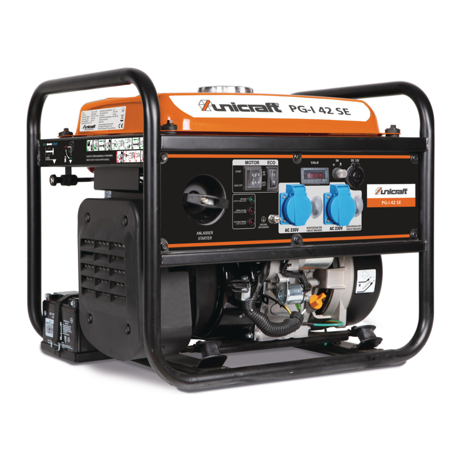
10 ON / OFF switch 11 ON / OFF switch ECO mode 12 Connection for 230V consumer 13 Circuit breaker 9A 14 Output 12 V DC 15 Ground connection 16 Control lights 17 Pull-wire starter PG-I SE Series | Version 1.04... -
Page 11: Control Elements And Functions
The valve knob must be set to "I" to start and operate the generator. Set the fuel tap to "O" when the engine is switched off and the generator is stored or transported. PG-I SE Series | Version 1.04... -
Page 12: Preparation And Set-Up
). Make sure that all connections are secure. this case, do not fill the generator with fuel or at- tempt to start it. Step 3: Secure the terminals with the rubber covers (if present). PG-I SE Series | Version 1.04... - Page 13 Fig. 10: Fill in oil Step 3: Wait until the oil has completely run into the conta- iner and the level has adjusted. Then check the correct oil level (1, Fig. 11). Fig. 7: Open the cover PG-I SE Series | Version 1.04...
- Page 14 Change the type of engine oil used according to weather conditions to meet engine requirements. Fig. 13: Filling up with fuel Step 4: Close the filler cap and wipe off any spilled fuel. Fig. 12: Temperature table oil PG-I SE Series | Version 1.04...
-
Page 15: Power Generation Capacity
Danger of crushing! not covered under warranty. Improper work on the generator may result in injury to fingers and hands. - Never reach into the generator during operation. PG-I SE Series | Version 1.04... -
Page 16: Before Starting
Step 2: Check grounding. Proper grounding of the gene- rator will prevent electric shock in the generator or connected electrical equipment. Proper grounding also prevents static electricity, which often builds up in ungrounded equipment. PG-I SE Series | Version 1.04... -
Page 17: Starting The Pg-I 42 Se Generator
Close the filler opening tightly with the cap. Wipe up spilled petrol! Fig. 16: Pull out the choke l NOTE! The choke does not have to be pulled out to start an already warm engine. PG-I SE Series | Version 1.04... -
Page 18: Activation Of The Eco Switch
When the smart switch is off, the en- operator. gine runs at normal operating speed. PG-I SE Series | Version 1.04... -
Page 19: Dc Outlet
If the engine does not start, wait at least 10 se- nerator to restore power. conds before operating the starter again. PG-I SE Series | Version 1.04... -
Page 20: Switching Off The Generator
Do not let the handle snap back after starting. Let the handle slide back to its original position carefully. - Let the motor run for 15 to 30 seconds and then turn the multiswitch to the RUN position. Fig. 26: Multiswitch OFF position PG-I SE Series | Version 1.04... -
Page 21: Connection Of Consumers
Consult the utility company or a qualified During parallel operation, the Eco switch on both genera- electrician before making power connections. tors should be in the same position. Connect the parallel power cable between two generators. PG-I SE Series | Version 1.04... -
Page 22: Care, Maintenance And Repair
All plastic parts and painted surfaces should be cleaned with a soft, damp cloth and some neutral cleaner. Re- move excess grease or leaked oil with a dry, lint-free cloth. Always keep the cooling fins clean and free. PG-I SE Series | Version 1.04... -
Page 23: Maintenance Schedule Pg-I 80 Se
Use a spark plug wrench to tigh- the filler neck. Never exceed the maximum fill ten the spark plug. level! Step 6: Attach the plug connector, mount the protective cap and cover. PG-I SE Series | Version 1.04... - Page 24 DO NOT expose the device to extreme conditions, excessive dust, dirt, moisture or corrosive vapors. 12.5.4 Clean spark protection Maintenance must be carried out every 6 months or every 100 operating hours. PG-I SE Series | Version 1.04...
-
Page 25: Maintenance Work Pg-I 80 Se
Step 2: Reach under the power generator and remove the black rubber seal under the oil drain plug. Step 3: Place a suitable container under the generator to collect the used oil. Step 4: Remove the oil filler cap / dipstick. PG-I SE Series | Version 1.04... - Page 26 Remove the cover and put it ster. aside. Step 1: Remove the two screws and take off the tail pipe Step 2: Remove the spark plug connector. and the spark arrester. PG-I SE Series | Version 1.04...
-
Page 27: Troubleshooting
Output indicator is switched off Check the AC load. Switch off the mo- and the overload indicator is swit- tor and restart. Check the cooling air in- ched on. take. Switch off motor and restart PG-I SE Series | Version 1.04... -
Page 28: Disposal, Recycling Of Used Devices
The item numbers of your device: Disposal notes for used lubricants are available from the Generator PG-I 42 SE: 6706420 manufacturer of the lubricants. If necessary, request the Generator PG-I 80 SE: 6706800 product-specific data sheets. PG-I SE Series | Version 1.04... -
Page 29: Spare Parts Drawings
15.2.1 Spare parts drawings PG-I 42 SE Spare parts drawing 1 Fig. 39: Spare parts drawing 1 PG-I 42 SE Spare parts drawing 2 Fig. 40: Spare parts drawing 2 PG-I 42 SE PG-I SE Series | Version 1.04... - Page 30 Spare parts Spare parts drawing 3 Fig. 41: Spare parts drawing 3 PG-I 42 SE Spare parts drawing 4 Fig. 42: Spare parts drawing 4 PG-I 42 SE PG-I SE Series | Version 1.04...
- Page 31 Spare parts Spare parts drawing Fig. 43: Spare parts drawing 5 PG-I 42 SE Spare parts drawing 6 Fig. 44: Spare parts drawing 6 PG-I 42 SE PG-I SE Series | Version 1.04...
- Page 32 Fig. 45: Spare parts drawing 7 PG-I 42 SE Spare parts drawing 8 Fig. 46: Spare parts drawing 8 PG-I 42 SE Spare parts drawing 9 Fig. 47: Spare parts drawing 9 PG-I 42 SE PG-I SE Series | Version 1.04...
-
Page 33: Spare Parts Drawings Pg-I 80 Se
Spare parts 15.3Spare parts drawings PG-I 80 SE Spare parts drawing 1 Fig. 48: Spare parts drawing 1 PG-I 80 SE PG-I SE Series | Version 1.04... - Page 34 Spare parts Spare parts drawing 2 Fig. 49: Spare parts drawing 2 PG-I 80 SE PG-I SE Series | Version 1.04...
-
Page 35: Electrical Circuit Diagram Pg-I 42 Se And 80 Se
Electrical circuit diagram PG-I 42 SE and 80 SE 16 Electrical circuit diagram PG-I 42 SE and 80 SE Fig. 50: Electrical circuit diagramPG-I 42 SE and 80 SE PG-I SE Series | Version 1.04... -
Page 36: Ec Declaration Of Conformity
Vehicles, boats and internal combustion engines - Radio disturbance characteristics - Limits and methods of measurement for the protection of off-board receivers Kilian Stürmer, Stürmer Maschinen GmbH, Responsible for the documentation: Dr.-Robert-Pfleger-Str. 26, D-96103 Hallstadt Hallstadt, 02.07.2019 ______________________ Kilian Stürmer Manager PG-I SE Series | Version 1.04... -
Page 37: Notes
Notes 18 Notes PG-I SE Series | Version 1.04... - Page 38 www.unicraft.de...
Need help?
Do you have a question about the PG-I SE Series and is the answer not in the manual?
Questions and answers