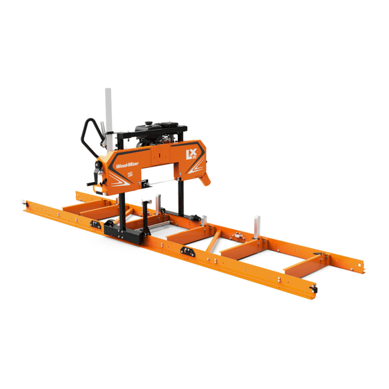
Wood-mizer LX25 Maintenance Manual
Sawmill
Hide thumbs
Also See for LX25:
- Safety, operation, maintenance & parts manual (91 pages) ,
- Safety, operation, maintenance & parts manual (67 pages)

Subscribe to Our Youtube Channel
Related Manuals for Wood-mizer LX25


Summary of Contents for Wood-mizer LX25
- Page 1 LX25 Sawmill Safety, Operation, Maintenance, & Parts Manual LX25 rev. A2.00 Safety is our #1 concern! May 2020 Form #2426 POWER OPTIONS: G7-LX WARNING! Read and understand this manual before using this machine.
- Page 2 For more information go to www.P65Warnings.ca.gov/wood. Active Patents assigned to Wood-Mizer, LLC Wood-Mizer, LLC has received patents that protect our inventions which are a result of a dedication to research, innovation, development, and design. Learn more at: woodmizer.com/patents ©2022 Wood-Mizer LLC...
-
Page 3: Table Of Contents
Blade Height Scale....................4-9 4.11 Water Lube Operation..................4-10 4.12 Transporting the Sawmill.................. 4-10 SECTION 5 MAINTENANCE Continuous maintenance ..................5-1 General maintenance................... 5-1 Engine maintenance .................... 5-2 SECTION 6 SAWHEAD PARTS Sliding Blade Guide Arm Assembly..............6-1 Table of Contents LX25 12/21/22... - Page 4 Kohler 9hp Gas Engine ..................7-1 Kohler 7hp Gas Engine (G7-LX) ................7-2 SECTION 8 BED AND CARRIAGE ASSEMBLY Bed........................8-1 Log Clamp ......................8-2 Carriage .......................8-3 Log Rest.......................8-5 Optional Log Ramps....................8-6 Optional Adjustable Feet..................8-7 Optional Log Taper Wedge ................8-8 LX25 12/21/22 Table of Contents...
-
Page 5: Section 1 Introduction
SECTION 1 INTRODUCTION About This Manual ® This manual replaces any previous information received on your Wood-Mizer equipment. The information and instructions in this manual do not amend or extend the limited warranties for the equipment given at the time of purchase. -
Page 6: Section 2 Safety
The procedures listed in this manual may not include all ANSI, OSHA, or locally required safety procedures. It is the owner/operator’s responsibility and not Wood-Mizer LLC to ensure all operators are properly trained and informed of all safety protocols. Owner/Operators are responsible for following all safety procedures when operating and performing maintenance to the equipment. - Page 7 Do not use flammable liquids (diesel fuel or kerosene) in the water lube accesso- ries. Clean fuel/flammable liquid spills immediately. NOTICE Remove blades from equipment before cleaning them with fuel/flammable liquid. Dispose of fuel/flammable liquids per local ordinances. Safety LX25 12/21/22...
- Page 8 Use a lifting device (fork lift, crane, etc.) for parts over 100 lbs. Use two persons for lifting parts over 50lbs. Keep all non-essential personnel out of the area while setting up the sawmill. LX25 12/21/22 Safety...
-
Page 9: Safety Decals
Blade Movement Direction 099220 Sawmill Covers Caution CAUTION! Close all guards and cov- ers before starting the machine. 099222 Warning Projectile Hazard Wear safety goggles. 1.For more information on lifting safety see NOISH Lifting Equation at https://www.cdc.gov/niosh/docs/94-110/ Safety LX25 12/21/22... - Page 10 Wear protective boots at all times when operating the mill! S12004g Use Eye Protection Wear safety goggles at all times when operating the mill! S12005g Use Ear Protection Wear ear protection at all times when operating the mill! LX25 12/21/22 Safety...
-
Page 11: Section 3 Setup
Remove and inspect the parts boxes Part # Description Part # Description Engine Manual M2426 Manual Operator's/Parts 130360 Bag Kit, LX25 Fastener X100-1050 Rod Lift Cable (See next table) C209 Black Brushed Bill Hat X100-1056 Cable, Lift Paddle X100-1057 Wrench, 7/8 Ratcheting... - Page 12 Setup Remove and inspect the parts boxes Part # Description Part # Description Pin, 3/8x2 1/4 SQ Wire Lock Clamp Assembly, Log Metric 014151 X200-1082 (F05022-25 incl in bag kit) Bracket, Scale Handle, 33/64 ID x 1-1/4 OD x X100-348 046627 4 PLASTIC (Sub 1) X100-984...
- Page 13 Setup Remove and inspect the parts boxes Part # Description Part # Description Bolt, M12-1.75x120 SHC Shim, .0075 Blade F05023-6 035248 Sweeper, Modular Track Hexagon Lift Cable X100-378 X100-1042 Water Tank Assembly Hook, Cover X100-970 X100-1020 F05011-45 Washer, 8mm Split Lock, Zn F05004-47 Bolt, M8-1.25x16 HH Zinc Setup...
- Page 14 Setup Remove and inspect the parts boxes Part # Description Part # Description Plate, T100 Drive/Idle Side Bracket, Center Bed Rail X100-929 123031 Rail Plate, T100 Safety Catch Rail Plate, T100 Cross Brace X100-930 X100-932 Lower Carriage Member (w/ Carriage Left Side Post X100-202 X100-1044 bearings installed)
- Page 15 Setup Remove and inspect the parts boxes Part # Description Part # Description Wldmnt, Carriage Right Side Channel, Upright Cross X100-1045 130947 Pist Bolt, M6-1.0x12 Nut, M601.0 Nylon F05005-99 F05010-200 Washer, M6 Flat Cable Ties F05026-1 F05089-3 Setup WM doc 12/21/223-5...
-
Page 16: Assemble The Bed Sections
Setup Assemble the bed sections BAG KIT 130360 BAG KIT, LX25 FASTENER F05022-25 Bolt, M10-1.5x120mm Hex Cl 8.8 F05022-3 Bolt, M10-1.5x30 Class 8 HH F05022-17 Bolt, M10-1.5x70 Carriage F05022-15 Bolt, M10-1.5x75 HH Class 8.8 F81003-125 Bolt, M10-1.5x85 Class 8 HH... - Page 17 Setup Assemble the bed sections 2. Assemble the remaining track rails and cross rail in a similar fashion. See FIG. 3-2. Direction of cut TDLX2503-02 FIG. 3-2 3. Connect the bed sections using a connecting plate, a clamp, and hardware. Nut, M10-1.5 Flanged Clamp Nylon Lock...
-
Page 18: Level The Bed
Setup Level the bed e. Fully tighten the plate bolts in the slotted holes on Nut, M10-1.50 Hex Nyl Lock Washer, 3/8 Flat SAE connecting plate. NOTE: Be sure the slotted holes on the connecting plate are connected to the same bed section on both sides of the bed frame. -
Page 19: Install The Mast
Setup Install the mast 4. When the bed is leveled, square up the log rest posts. Tighten the log rest bracket screws. See FIG. 3-7. Square 5. Recheck saw bed for level! Install the mast Log Rest Post Prepare the mast carriages Log Rest Bracket The sawhead carriages come mostly assembled from the factory. - Page 20 Setup Prepare mast Prepare mast Carriage Post, Right Side Upright Cross Channel Engine Muffler Notch Bolt, M8x8 SH Shoulder Plain Hexagon, Lift Cable Nut, M8-1.25 Free Rod, Lift Cable Carriage Post, Left Side Washer, M8 Flat Nut, M8-1.25 Bolt, M10-1.5x75 Nylock Nut, M10-1.50 FIG.
-
Page 21: Install The Sweepers And Sawhead Stops
Setup Install the sweepers and sawhead stops NOTE: This prevents the sawhead from sliding up the mast while mounting it. FIG. 3-12. Stop Pins 5. Raise the sawhead to the upright position. 6. Install the entire head and mast assembly on the bed rails. -
Page 22: Install The Operator's Handle
Setup Install the operator’s handle 2. Attach the stop blocks (X100-1275) on the outside surface of the bed section at the head of the bed using M10-1.5x30 bolts. Tighten the nuts. See FIG. 3-15. 3. Repeat at the foot end of the rail. Nut, M10-1.5 Bolt, M10-1.5x30 Stop Block... - Page 23 Setup Install the Engine Cable mounting bracket Direct exhaust up and away from operator Nut, M10 Hex Nylock Washer, M10 Flat Bolts, M10x50mm 55007-2 55007-4 FIG. 3-18 FIG. 3-19 4. Install the exhaust deflector. See Fig. 3-19 5. Install the clutch idler pulley. NOTE: For the 9HP engine mount the bolt in the hole number 1 and for the 7HP...
-
Page 24: Install The Throttle Cable
Setup Install the throttle cable 11. Install the belt on bandwheel and pulleys. See Fig. 3-22. Bandwheel Belt Pulley Pulley FIG. 3-22 Install the throttle cable 1. Replace the existing cable bracket on the engine with the supplied cable bracket. See Fig. 3-23. 2. -
Page 25: Install The Clutch Cable
Setup Install the clutch cable 5. Attach the throttle cable to the clutch. See Fig. 3-24. Throttle Cable Clutch cable (installed later) Set throttle cable in 250011 the “slow” position FIG. 3-24 6. Adjust and tighten the throttle cable at the throttle lever. Loosen, if necessary NOTE: Some engines are shipped with the throttle lever tight. -
Page 26: Assemble The Up/Down Crank
Assemble the up/down crank 6. Tighten the clutch cable in the bracket with a wrench. See FIG. 3-28. NOTE: The throttle should be adjusted after the LX25 is fully assembled and ready for use. Nut, M6 8 FE/ZN5 PN-85/M-82144 Nut, M6-1.0 Nylon... -
Page 27: Install The Scale
Setup Install the scale 2. Attach the lift cables from the hardware kit on the lift cable rod (attached earlier to the upright cross channel on the mast). See FIG. 3-10. and FIG.3-31 3. Back out the set screw from the crank shaft with a 3mm hex wrench and thread the lift cable through the hole in the crank shaft. -
Page 28: Install The Dust Chute
Setup Install the dust chute 3.12 Install the dust chute Bolt, M6-1 x 14 Class 8 Fasten the dust chute to the sawhead with the three M6-1 x 14 Class 8 bolts and nuts provided in the hardware kit. See FIG. - Page 29 Setup Install the Blade 4. Place the new blade around the blade wheels and through the blade guides. See FIG. 3-34.. 55001-38 FIG. 3-34 NOTE: When installing a blade, make sure the teeth are pointing t toward the dust chute. If necessary, invert the blade as shown in the video. 5.
-
Page 30: Install The Lube Water Tank
Setup Install the lube water tank 3.14 Install the lube water tank Nut, M6-1.0 Nylon Lock NOTE: Before install- ing the water tank, Water Lube check for blade Tank straightness. "Blade straightness." In order to loosen the Washer, 1/4 Flat guide block, the water tank must be Bolt, M6-1x12... -
Page 31: Section 4 Sawmill Operation
When the blade tracks straight, tighten the rear set nuts. FIG. 4-3 Blade Guide Vertical Tilt Alignment The blade guides should be adjusted properly in the vertical plane. If the blade guides are tilted vertically, the blade will try to travel in the tilted direction. Sawmill Operation LX25 12/21/22... - Page 32 2. Remove the clip from the blade guide alignment tool and place the tool against the face of the outer blade guide roller. See FIG. 4-6. Blade Guide 3H0802-5B FIG. 4-6 Alignment Tool LX25 12/21/22 Sawmill Operation...
- Page 33 A square ceramic guide lies in the middle of the blade guide assembly. This guide should be positioned approximately 1/8 inch from blade back. Use the set screw on the side of the blade guide assembly to hold the position of the square guide. (See FIG. 4-10 .) Sawmill Operation LX25 12/21/22...
- Page 34 Conversely, when the throttle handle is released, the engine should revert to idle, and the blade drive wheel stop turn- ing. (See FIG. 4-11 .) Adjustment nuts Clutch Set screw 100B-016 FIG. 4-10 FIG. 4-11 LX25 12/21/22 Sawmill Operation...
- Page 35 2. Measure the blade from a tooth pointing down on both sides of the sawhead. Pull the adjustable blade guide arm all the way out before measuring. (See FIG. 4-13 .) 100B-019 FIG. 4-13 Sawmill Operation LX25 12/21/22...
-
Page 36: Starting The Engine/Motor
3. Raise the side supports on the sawmill bed to prevent the log from falling off the side of the bed. 4. Position the log parallel to the sawmill bed. 5. Roll the log onto the sawmill bed. LX25 12/21/22 Sawmill Operation... -
Page 37: Level A Log
Use crank handle to change over them. sawhead height FIG. 4-18 3. Ensure the log is clamped securely. 4. Open the fuel supply valve and turn on the ignition by moving the ignition/fuel lever to the “ON” position. Sawmill Operation LX25 12/21/22... -
Page 38: Feed Operation
5. Start the water lube if necessary to prevent sap buildup on the blade. 6. Feed the blade into the log slowly. 7. When the teeth exit the end of the log, disengage the clutch and remove the cut slab. LX25 12/21/22 Sawmill Operation... -
Page 39: Edging
Make a trim cut. Return the mast for the second cut and lower it 1 1/8" (29 mm) below the original measurement. (The extra 1/8" (3 mm) allows for saw kerf and shrinkage of the lumber.) FIG. 4-20 Sawmill Operation LX25 12/21/22... -
Page 40: Water Lube Operation
2. Divide the bed frame into the segments. 3. Slide the bed frame segments into the truck. 4. Use a forklift to load the sawhead with the mast and bed segment into the truck and secure it with transport straps. 4-10 LX25 12/21/22 Sawmill Operation... -
Page 41: Section 5 Maintenance
Maintenance Continuous maintenance SECTION 5 MAINTENANCE WARNING!Shut down the sawmill and allow all moving parts to come to a complete stop before removing any guards and covers. Failure to do so may result in serious injury or death. Continuous maintenance Rails, rollers, and sweepers Proper maintenance of the sawmill carriage rollers and rails is critical for smooth operation of the sawmill. -
Page 42: Engine Maintenance
Maintenance Continuous maintenance Monthly (160 hours of operation) Grease the lift cables on both sides of the sawhead with white lithium grease. (See FIG. 5-2 .) Grease FIG. 5-2 100B-025 Engine maintenance Refer to the manufacturer’s engine manuals for maintenance. -
Page 43: Section 6 Sawhead Parts
QTY. X100-963 Assembly, Sliding Guide 086875 Sleeve, Vinly Guard X100-336 Lever, Blade Guide 025248 Grommet, Rubber 3/8 Dia F05010-132 Nut, M8-1.25 Hex Nylock F05026-4 Washer, M8 Flat F05004-47 Bolt, M8x1.25x16mm HH X100-1066 Weldment, Sliding Guide T100 Sawhead Parts LX25 12/21/22... -
Page 44: Blade Guide Assembly
Assembly, Blade Guide Idle Side F05010-132 Nut, M8-1.25 Hex Nylock F05026-4 Washer, M8 Flat X200-433 Ceramic, 7/8 Dia x .825 Long X100-977 Block, Blade Guide T100 F05026-2 Washer, M6 Split Lock F05020-32 Bolt, M6-1.0 x 65 HH Class 8.8 LX25 12/21/22 Sawhead Parts... - Page 45 Bolt, M6-1.0 x 65 HH Class 8.8 F05020-24 Screw, M6-1x8 SHSS X200-434 Ceramic, .49 Sq x .88 Long F81002-10 Bolt, M8x50MM Gr.5 HH UTW31-132-10 Blade, 042 x 1¼ x 132; 10° 035248 Shim, .0075 Blade Not shown Sawhead Parts LX25 12/21/22...
-
Page 46: Clutch Assembly
Nut, M5-.8 Class 8 Hex Nylock X100-917 Bearing, Clip, 1/2 014820 Collar, Lock 1/2IDx7/8OD F05020-39 Bolt, M6-1x10mm SH Shoulder F05011-18 Washer, #10 SAE Flat F05022-16 Bolt,M10-1.5x60 HHC F05026-1 Washer, M6 Flat Class 4 F05011-2 Washer, 1/2 SAE Flat LX25 12/21/22 Sawhead Parts... -
Page 47: Scale And Sawdust Chute
Scale and Sawdust Chute Scale and Sawdust Chute 10 11 12 100b-028 PART # DESCRIPTION COMMENTS QTY. 130301 Assembly, Scale LX25 123059 Decal, Wood-Mizer Inch Scale X100-348 Bracket, Scale F05020-8 Bolt, M6-1.0x30 Class8 HH F05026-1 Washer, M6 Flat Class 4... -
Page 48: Cover Hold-Up Latch
Nut, M6-1.0 Free Nut Zinc F05026-1 Washer, M6 Flat Class 4 F05011-134 Washer, M10 Flat SAE X100-920 Latch, Cover F05022-9 Bolt, M10x10 SH Shoulder Plain X200-997 Spring, 7/16ODx2x.041 Wire Ext F05010-200 Nut, M6-1.0 Nylon Lock F05010-132 Nut, M8-1.25 Hex Nylock LX25 12/21/22 Sawhead Parts... -
Page 49: Water Tank
X100-970 Assembly, Water Tank X100-904 Tank, Water, 4 qt F05011-11 Washer, 1/4 SAE Flat F05005-99 Screw, M6-1x12 HHC FT GR8-8 Din 933 F05010-200 Nut, M6-1.0 Nylon Lock X200-983 Valve, 1/4 Water Shutoff X100-982 Tubing, Vinyl, 1/4x3/8x12 Sawhead Parts LX25 12/21/22... -
Page 50: Up/Down Slides
QTY. X100-962 Assembly, Up/Down Slide F05021-11 Screw, M8-1.25x30 HHC F05026-4 Washer, M8 Flat X100-327 Block, Vertical Slide Guide F05010-132 Nut, M8-1.25 Hex Nylock F05010-162 Nut, M8-1.25 Free Zinc Plate F81002-19 Bolt, M8x50 8.8 HH FT Zinc LX25 12/21/22 Sawhead Parts... -
Page 51: Winch
F05011-16 Washer, 5/16 Standard Flat F05011-13 Washer, 5/16 Split Lock F05004-47 Bolt, M8-1.25x16 HH Zinc F05011-134 Washer, M10 Flat X200-992 Spring, B66 X100-385 Pawl, Winch F05010-200 Nut, M6-1.0 Nylon Lock F05004-270 Nut, M10-1.50 Hex Nyl Lock Sawhead Parts LX25 12/21/22... - Page 52 Sawhead Parts Winch PART # DESCRIPTION COMMENTS QTY. F05027-19 Nut, M12-1.75 Zinc Jam F05011-123 Washer, 12MM Split Lock F05010-212 Nut, M12x1.75 Free Znc 046647 Handle, 33/64IDx1 1/4ODx4 Plastic F05023-6 Bolt, M12-1.75x120 SHC 6-10 LX25 12/21/22 Sawhead Parts...
-
Page 53: Throttle Lever
F05010-200 Nut, M6-1.0 Nylon Lock F05026-1 Washer, M6 Flat Class 4 X100-369 Lever, Throttle F81031-1 Nut, M6-1.0 Free Nut Zinc X100-210 Handle Weldment, Push F05020-32 Bolt, M6-1.0 x 65 HH Class 8.8 X100-392 Cable, Clutch Sawhead Parts LX25 12/21/22 6-11... -
Page 54: Blade Tension Assembly
F05020-44 Screw, M6-1.0 Wing F05027-27 Nut, Wing M6x1 Zinc F05010-227 Nut, 1/2-10 Acme F05010-10 Nut, 3/8-16 Hex Nyloc F05011-16 Washer, 5/16 Standard Flat F05007-6 Bolt, 3/8-16x3 1/2 Gr8 YZC X100-1057 Wrench, 7/8 Ratcheting Not shown 6-12 LX25 12/21/22 Sawhead Parts... -
Page 55: Band Wheel Assembly, Driver Side
Sheave, Bandwheel, 15 3/8 OD P08066 Bearing, 6305 62 OD x 25 ID x 17 W S08220 Washer, .313x1.5x.125 Retaining F05004-40 Bolt, M8x1.25x25mm C/S 8.8 Din 933 HH X100-905 Belt, B69 Carlisle Super II (Drive side) Sawhead Parts LX25 12/21/22 6-13... -
Page 56: Band Wheel Assembly, Idle Side
Bearing, 6305 62 OD x 25 ID x 17 W F04254-21 Ring, 2 7/16 IR N 5002-244 Beveled Snap S08220 Washer, .313x1.5x.125 Retaining F05004-40 Bolt, M8x1.25x25mm C/S 8.8 Din 933 HH X100-900 Belt, B47.4 (Idle side) 6-14 LX25 12/21/22 Sawhead Parts... -
Page 57: Sawhead Cover
X100-967 Assembly, Cover T100 F05005-99 Screw, M6-1x12 HHC FT GR8-8 Din 933 F05026-1 Washer, M6 Flat Class 4 X200-913 Bracket, Latch F05027-3 Nut, M5-.8 Class 8 Hex Nylock X100-922 Weldment, Cover F05020-38 Screw, M5-.8x25mm SHBC Sawhead Parts LX25 12/21/22 6-15... - Page 58 Bolt, M5-.8 x 10 Class 8 HH X100-999 Latch, Vibration Cover F05027-3 Nut, M5-.8 Class 8 Hex Nylock X100-1019 Shim, Blade Guide F05010-132 Nut, M8-1.25 Hex Nylock F05010-162 Nut, M8-1.25 Free Zinc Plate F81002-10 Bolt, M8x50MM Gr.5 HH X100-201 Sawhead Weldment 6-16 LX25 12/21/22 Sawhead Parts...
-
Page 59: Decals
Decal, Close Guards Before Operating 096321 Decal, Blade Movement Direction 003325 Decal, Wood-Mizer Website Logo 099222 Decal, Saw Dust Protection-Pictogram 079278 Decal, Wood-Mizer Quality & Information S12004G Decal, Eye Warning 501465 Decal, Wear Safety Boots Sawhead Parts LX25 12/21/22 6-17... - Page 60 Decal, Blade Alignment 096317 Decal, Read Manual Before Operating 099921 Decal, Keep a Safe Distance 515084 Decal, Timbery Blade Tension 107171 Decal, White WM 123059 Decal, Wood-Mizer Inch Scale 015820 Decal, LT15 ID P09971 Decal, VIN Overlament 6-18 LX25 12/21/22 Sawhead Parts...
-
Page 61: Section 7 Engine Parts
Washer, Split Lock 7/16 Zinc X100-1094 Washer, 7/16" ID 1" x 1-1/4" Stepped X100-1062 Sheave, 1B34-SH 039202 Bushing, SHx1 S04124 Key, 1/4 x 1 11/16 F05004-270 Nut, M10-1.50 Hex Nyl Lock 110187 Deflector, Kohler 14HP Exhaust Engine Parts LX25 12/21/22... -
Page 62: Kohler 7Hp Gas Engine (G7-Lx)
Washer, 5/16 SAE Flat F05007-154 Screw, 3/8-24x3/4 SHC B/O F05011-4 Washer, 3/8 Split Lock F05011-126 Washer, 3/8 Standard Flat X100-1081 Sheave, BK34 x 3/4 Bore S31027 Key, 3/16 Sqx1 130992 Sleeve, LX25G7 Motor 110187 Deflector, Kohler 14HP Exhaust LX25 12/21/22 Engine Parts... -
Page 63: Section 8 Bed And Carriage Assembly
Bed and Carriage Assembly SECTION 8 BED AND CARRIAGE ASSEMBLY TDLX2503-01 PART # DESCRIPTION COMMENTS QTY. 128353 BED ASSEMBLY, LX25 014151 Pin, 3/8x2 1/4 Sq Wire Lock X100-929-W Plate, T100 Drive/Idle Side Rail 123031-W Bracket, Center Bed Rail F81003-125 Bolt, M10-1.5x85 Class 8 HH... -
Page 64: Log Clamp
075295 Block, Clamp Point 071343 Weldment, Clamp Post Tube 071350 Assembly, Clamp Screw F05022-21 Bolt, M10-1.5x140 HH FT Not used on LX25 F05011-3 Washer, 3/8 Flat SAE F05022-25 Bolt, M10-1.5x120mm Hex Cl 8.8 071034 Spacer, 2012 Clamp Mount X200-1041 Spacer, .379IDx.625ODx.480Long... -
Page 65: Carriage
Sweeper, Modular Track F05010-85 Nut, M10-1.5 Hex F05011-134 Washer, M10 Flat SAE F05015-33 Screw,#10x3/4 Sl Hex Washer Hd Sht Metal X200-957 Bearing, LLU 6302 X200-348 Bushing, Carriage Wheel F05022-3 Bolt, M10-1.5x30 Class 8 HH Bed and Carriage Assembly LX25 12/21/22... - Page 66 Bearing, LLU 6200 F81003-11 Bolt, M10-1.5x25mm HH Gr8.8 F05010-132 Nut, M8-1.25 Hex Nylock F05026-4 Washer, M8 Flat F05010-162 Nut, M8-1.25 Free Zinc Plate X100-1050 Rod, Lift Cable X100-1042 Hexagon, Lift Cable F05021-29 Bolt, M8x8mm SH Shoulder LX25 12/21/22 Bed and Carriage Assembly...
-
Page 67: Log Rest
DESCRIPTION COMMENTS QTY. X200-1026 Post, Log Rest F05022-3 Bolt, M10-1.5x30 Class 8 Hex Head F05011-134 Washer, M10 Flat SAE X200-1027 Bracket, Log Rest F05027-47 Nut, M10-1.5 Flanged Nylon Lock X200-1045 Post, Log Rest, Short Bed and Carriage Assembly LX25 12/21/22... -
Page 68: Optional Log Ramps
Washer, M10 Flat SAE F05004-270 Nut, M10-1.50 Hex Nyl Lock 123099 Weldment, Log Ramp LX55/25 f05022-13 Bolt, M10-1.5x110 Class 8 HH P04060 Spring, Old Style PWR/Feed &T110 Counter F05022-20 Bolt, M10-1.5x100 HH Class 8.8 LX25 12/21/22 Bed and Carriage Assembly... -
Page 69: Optional Adjustable Feet
Washer, M20 Flat Zinc F05027-26 Nut, M20-2.5 Free 514997_US Assembly, Bed Level 514996-1_US Weldment, Bed Level 130833 KIT, SAWMILL FEET (FOR OPTIONAL BED SEGMENTS) F05027-26 Nut, M20-2.5 Free F05026-16 Washer, M20 Flat Zinc 514996-1_US Weldment, Bed Level Bed and Carriage Assembly LX25 12/21/22... -
Page 70: Optional Log Taper Wedge
Bed and Carriage Assembly Optional Log Taper Wedge Optional Log Taper Wedge PART # DESCRIPTION COMMENTS QTY. WLDMNT, LOG TAPER WEDGE 130005 LX25 12/21/22 Bed and Carriage Assembly...
Need help?
Do you have a question about the LX25 and is the answer not in the manual?
Questions and answers