Table of Contents
Advertisement
Quick Links
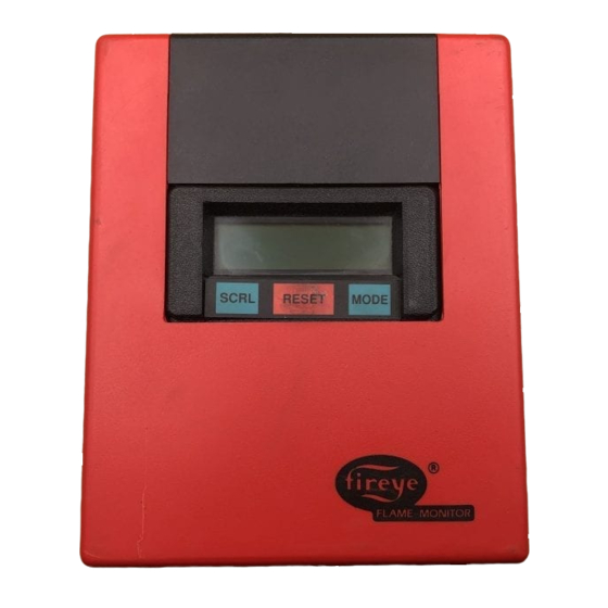
E110 with ED510 Display Module
DESCRIPTION
The Fireye
control system designed to provide the proper burner sequencing, ignition and flame monitoring pro-
tection on automatically ignited oil, gas, and combination fuel burners. In conjunction with limit and
operating controls, it programs the burner/blower motor, ignition and fuel valves to provide for
proper and safe burner operation. The control also provides current operating status and lockout
information in the event of a safety shutdown. The manner in which this information is displayed is
dependent on the type of programmer (EP or EPD) and display module (ED510 or ED500).
to Flame-Monitor PROGRAMMER SELECTION later in this document for the various combina-
tions of programmer and display modules.
The E110 consists of the EB700 chassis, dust cover, and shortened mounting screw (P/N 48-1836).
The display module (ED510), if required, must be ordered separately. Interchangeable programmer
and flame amplifier modules allow for complete versatility in selection of control function, timing,
and flame scanning means. Functions such as pre-purge, recycling interlocks, high fire proving inter-
lock, and trial for ignition timing of the pilot and main flame are determined by the programmer
module. The E110 Flame-Monitor can be used with ultra-violet, auto-check infrared, flame rod, or
self-check ultraviolet flame scanners by choosing the proper amplifier module.
The eighteen (18) terminal wiring base allows for many functional circuits including motors, valves,
and ignition transformers as well as multiple interlocks such as high purge, low purge, fuel valve and
running interlock circuits. The E110 uses the same wiring base as the Fireye E100 Flame-Monitor
control, D Series and C Series Controls and is directly interchangeable with most models without
rewiring.
Additional functions of the Flame-Monitor system include:
•
A non-volatile memory which allows the control to remember its history and present position
even when power is interrupted.
•
A constant flame signal read-out via display module or 0-10 VDC output (EPD
programmers only).
•
Read-out of main fuel operational hours and complete cycles via display module.
•
Modbus communications via RS485 multi-drop link.
•
Dipswitches located on the EP programmer to allow selectable purge time.
•
A run/check switch which allows the operator to stop the program sequence in any of three dif-
ferent positions (Purge, PTFI, or Auto).
•
Remote Display Capability.
•
Annunciate 16 additional interlocks using E300 Expansion Module.
*
The ED500 display was the predecessor of the ED510 display and uses an older design. It does not have the latest features
of the ED510 display module.
®
E110 FLAME-MONITOR™ System is a microprocessor based burner management
®
E110 FIREYE
FLAME-MONITOR
BURNER MANAGEMENT CONTROL
FOR USE WITH THE
MICROPROCESSOR-BASED
EP AND EPD STYLE
PROGRAMMER MODULES
E-1101
MARCH 28, 2013
™
APPROVED
*
Refer
1
Advertisement
Table of Contents

Subscribe to Our Youtube Channel
Related Manuals for Fireye FLAME-MONITOR E110


Summary of Contents for Fireye FLAME-MONITOR E110
- Page 1 The E110 uses the same wiring base as the Fireye E100 Flame-Monitor control, D Series and C Series Controls and is directly interchangeable with most models without rewiring.
- Page 2 ® CAUTION: While programmers are mechanically interchangeable in that they mate with a common wiring base, you should select the correct model for your application. Inappro- priate application of a control could result in an unsafe condition hazardous to life and property.
- Page 3 ® ELECTRICAL RATINGS VA ratings (not specified as pilot duty) permit the connection of transformers and similar devices whose inrush current is approximately the same as their running current. VA Pilot Duty ratings permit the connection of relays, solenoid valves, lamps, etc. whose total oper- ating load does not exceed the published rating and whose total inrush current does not exceed 10 times the rating.
- Page 4 EP-2601, EPD-2601 Programmers, Non-Modulating EP-3801, EPD-3801 Amplifiers EAMP1 Display, ED510 ED-5101 Expansion Module E-3001 All bulletins are available in .pdf format at www.fireye.com. FLAME AMPLIFIER SELECTION FIREYE P/N DESCRIPTION USE WITH SCANNER EUV1 Standard UV Amplifier UV1A, UV8A 45UV3, UV2 E1R1...
- Page 5 EP390 90 sec. purge NOTE: The EP programmers listed above are available in both Spanish and French languages. Consult factory or your local Fireye distributor for ordering information. SELECT DISPLAY Required for EP Programmers, Optional for EPD programmers ED510 2 line x 16 character LCD display.
- Page 6 ® FIREYE P/N DESCRIPTION BULLETIN ED510 Display Module (2 line x 16 characters LCD Display) ED-5101 129-145-1, -2, -3 Remote Display Mounting Kit (for ED510) with 4', 8' or 2' cable respectively E-8002 E350-3, -6 Expansion Module cables in 3' and 6' lengths...
- Page 7 ® FLAME-MONITOR Ordering Information E110 Flame-Monitor (One required) ED510 Display Module E110 consists of: Required with EP Programmers EB700 Chassis Optional with EPD Programmers EC600 Dust Cover Mounting Screw (48-1836) EP programmers must have an Eng. code of 28 or later (e.g.
- Page 8 ® FLAME SCANNERS UV90 UV8A 45UV5 45UV3-1050 69ND1 48PT2-9000 UV1A CAUTION: The UV1, UV2, UV8A, UV90 and 45UV3 ultra-violet flame scanners and associ- ated amplifier modules are non-self checking UV systems and should be applied only to burn- ers that cycle often (e.g.: a minimum of once per 12 hours) in order for the safety checking circuit to be exercised.
- Page 9 ® FIREYE Pre-purge Proven Proven Intermittent Interrupted Early Spark Pilot Main Running Firing Rate PART program- High Fire Low Fire Ignition/ Ignition/ Termination Trial-for-Ignition Trial-for-Ignition Interlock Motor NUMBER ming Purge Start Pilot Pilot (3/P CKT) Circuit Term 5 (Seconds) Interlock...
- Page 10 90 degrees C. Good electrical wiring practice should be followed to ensure an adequate ground system. Refer to Fireye Service Note 100 separately and Gen- eral Grounding Rules, later in this document, for recommended grounding methods A good ground system should be provided to minimize the effects of AC quality problems.
- Page 11 Refer to the suggestions shown in this bulletin before proceeding to power the Fireye E110 Flame-Monitor system. Items such as scanner installation, short circuit tests and safety information should be reviewed.
- Page 12 ® TYPE EP(D)160 DIPSWITCH SETTINGS NON-RECYCLE RUNNING INTERLOCKS (3/P) PURGE TIME - 30 SEC.* FLAME FAILURE RESPONSE TIME 4 SEC. INACTIVE Down Down Down Down PROGRAMMING SEQUENCE CLOSED FIRING L1/13 L1/13 CLOSED (MD) PERIOD (D8) PURGE POST PURGE Refer to appropriate programmer 30 SEC 15 SEC 30 SEC...
- Page 13 ® The trial for ignition period begins with Terminal 5 and 6 being energized simultaneously. This is known as PTFI (Pilot Trial for Ignition). The ED510 will display: PTFI 0:02 IGNITION TIMING This period is ten seconds in duration. If no flame is detected after ten seconds, the control will de- energize Terminals 5 and 6 and lockout.
- Page 14 ® LOCKOUTS When a safety shutdown occurs, the control will display a message indicating LOCKOUT and the reason for the lockout. The alarm circuit (Terminal “A”) will be energized. The non-volatile memory will remember the status of the control even if a power failure occurs. By momentarily depressing the reset button on the display, the control can be reset.
- Page 15 ® Fuel Valve End Switch Interlock: This is generally an integral switch mounted on the main fuel valve and activated by the valve stem. It is connected between Terminal 3 & 13. The fuel valve end switch interlock prevents a burner start-up if the valve stem is not in the “valve closed”...
- Page 16 ® EP(D)160 LOGIC FLOW DIAGRAM NORMAL CYCLE MODULATOR SENT POWER ON TERMINALS L1 & L2 TO LOW FIRE STANDBY L1-13 OPEN OPERATING CONTROL CLOSED L1-13 ARE LIMITS L1 TO 13 MADE? IS F.V.E.S. MADE 13-3 LOCKOUT + LOCKOUT + IS AIR FLOW SWITCH MADE? 3-P MODULATOR SENT FROM LOW TO HOLD 10 MIN.
- Page 17 ® ED510 MESSAGES RUN MESSAGES The operating control of the FLAME-MONITOR (terminals L1-13) is open. STANDBY L1-13 OPEN Firing rate motor sent to high fire (term. 10-X made), purge timing displayed PURGE 0:05 upper right hand corner. HIGH FIRE PURGE Firing rate motor sent to low fire (term.
- Page 18 ® The control has finished purge and the firing rate motor is driving to the low fire HOLD PURGE 0:00 position (term. 10-12 made) waiting for the low fire start switch (term. M-D) to M-D LIMIT OPEN close. It will hold this position for ten (10) minutes and then lockout if the M-D circuit does not close, excluding the EPD167.
- Page 19 ® Flame has been sensed during the burner off time (term. L1-13 open) or during the purge LOCKOUT STANDBY period for sixty (60) seconds. FALSE FLAME A flame failure occurred during the pilot trial for ignition period. LOCKOUT PTFI FLAME FAIL A flame failure occurred during the main trial for ignition period.
- Page 20 — The E300 Expansion Module has a — Replace E300 Expansion Module. CHECK EXPANSION MODULE defective optocoupler. LOCKOUT AUTO — Amplifier has failed diagnostic checks. — Replace amplifier. AUTO CHECK AMPLIFIER FAIL FIREYE ED510 — Defective programmer. — Replace programmer. SYSTEM ERROR...
- Page 21 ® HISTORICAL INFORMATION /SYSTEM SUB-MENUS At any time the control is powered, the SCRL key will scroll through and display the total number of burner cycles, burner lockouts, and system hours on the bottom line of the ED510 display. The top line will continue to show the current run mode of the control (e.g.
- Page 22 ® LOCKOUT HISTORY The sub-menu “LOCKOUT HISTORY” will display the last six (6) lockouts, along with the burner cycle and burner hour when the lockout occurred. When the MODE key is pressed, the screen will display the most recent lockout condition and the number of that lockout (e.g. LO #127 represents the 127th lockout of that control).
- Page 23 ® TO MODIFY THE E300 MESSAGES All three keys: Mode, Reset and Scroll, are used to modify the E300 messages. The Mode key is used to enter or exit the sub-menu associated with the E300 messages. The Scroll key is used to advance through the various terminals or selectable messages.
- Page 24 ® USER PROGRAMMED E300 MESSAGES In addition to selecting the lockout alarm messages for the E300 Expansion Module from a menu selection via the ED510 display, the user can also program any message (up to 40 characters in length) for the individual terminals of the E300 using a dumb terminal (or PC with communication software) and the appropriate interface cables.
- Page 25 The EP(D) programmer updates the messages to the ED510 display at least once every 8 seconds. If the ED510 display does not receive information from the EP(D) programmer within 10 seconds the ED510 will display: FIREYE ED510 WAITING FOR DATA...
- Page 26 ® COMMUNICATIONS The protocol to be used is Modbus RTU. This is implemented by the master (PC, PLC, etc.) issuing a poll to the slave (Flame-Monitor) and the slave responding with the appropriate message. A typical format of a poll request is as follows: DST refers to the logical address of the slave.
- Page 27 ® 2nd Most Recent Lockout Data 3rd Most Recent Lockout Data 4th Most Recent Lockout Data 5th Most Recent Lockout Data 6th Most Recent Lockout Data Input limits and Returns input limits state and lower and upper expansion module Expansion Module (E300) registers.
- Page 28 For the INPUTS, a 1 in the interlock position defines the interlock as being on or active where a 1 in any bit position in the OUTPUT register signifies the relay as being energized. Refer to Fireye bulletin E-3001 for terminal designations Table 3:...
- Page 29 ® Table 2: EXPLANATION OF LOGSTAT LOGIC DISPATCHER VALUE MODULE FUNCTION MPOSTIDLE MPREPURGE1 Wait for air flow and/or high fire switch to close MPURGE Open Damper Purge MPOST PURGE Low Fire Purge MTFI Pilot Trial MTFMF Main Trial MAUTO AUTO MSHTDWN1 Post Purge MSHTDWN2...
- Page 30 ® Table 1- Message Table E110 FLAME-MONITOR MESSAGES L1-13 OPEN HOLD FALSE FLAME- STANDBY LOW FIRE PURGE HOLD D-8 LIMIT OPEN- PURGE HOLD 3-P AIR FLOW OPEN LOCKOUT LINE FREQUENCY NOISE DETECTED LOCKOUT FLAME FAIL - PTFI CHECK UNIT ADDRESS HOLD M-D LIMIT OPEN IGNITION TIMING - PTFI FLAME SIGNAL - AUTO...
- Page 31 ® SYSTEM DIAGNOSTIC MESSAGES LOCKOUT CHECK CHASSIS LOCKOUT CHECK PROGRAMMER LOCKOUT CHECK AMPLIFIER LOCKOUT CHECK EXPANSION MODULE LOCKOUT AMPLIFIER AUTO CHECK FAIL LOCKOUT SCANNER NOISE LOCKOUT CHECK SCANNER E300 EXPANSION MODULE HOLD MESSAGES L1-13 AUX #1 OPEN (TERMINAL 20) L1-13 AUX #2 OPEN (TERMINAL 21) L1-13 AUX #3 OPEN (TERMINAL 22) 3-P HIGH WATER (TERMINAL 23) 3-P LOW WATER (TERMINAL 24)
- Page 32 Motor Switching Plug In Flame Burner Motor Control Circuit (See Insert) (See Insert) Flame Amplifier Control Circuit Only FIREYE WIRING BASE TERMINALS 15 SEC PURGE IMPORTANT; A Good Note: When A Flame Rod Is FLAME INT. * Earth Ground is...
- Page 33 The function of the low fire start and high fire purge interlock circuits internally in a new Fireye Flame-Monitor unit is accomplished by highly reliable solid state electronic circuitry. This prohibits the connection of power consuming devices (i.e. lamps, annunciators, relays, timers, etc.) to the D or 8 terminals.
- Page 34 ® CENTER OFF SWITCH 3PDT SHOWN IN OIL POSITION INTERRUPT POWER TO F.M. R1NO R1NC CONTROL INPUT VOLTAGE IGNITION PILOT VALVE MAIN GAS VALVE MAIN OIL VALVE TRANSFORMER INSTALLATION /TESTING Check-Run Switch The Check-Run switch is located on the top of the EP Programmer Module and can be used to stop the control in its firing sequence at any time except during MTFI.
- Page 35 ® After the PTFI period has begun, switching back to the Check position will stop the program in the PTFI period, allowing for pilot and/or scanner alignment adjustments to be made. The control will display: CHECK PTFI FLAME SIGNAL It will hold in this position indefinitely as long as the flame signal strength is above the threshold of 10.
- Page 36 ® TEST CHECKOUT PROCEDURES Normal Pilot Flame Test CAUTION: Before making a pilot flame test, manually shut off the fuel supply to the main burner. At the start of PTFI, place the Check-run switch in the check position. Observe the pilot flame signal on the display. If the average signal is below the minimum of 10, readjust the pilot flame or realign the flame detector.
- Page 37 ® REFRACTORY REFRACTORY REFRACTORY MAIN MAIN MAIN FLAME FLAME FLAME PILOT PILOT PILOT FLAME FLAME FLAME MAIN MAIN MAIN BURNER BURNER BURNER PILOT PILOT PILOT BURNER BURNER BURNER SCANNER SCANNER SCANNER MINIMUM PILOT NORMAL PILOT INSUFFICIENT PILOT Scanner Wiring Care should be taken to see that ignitor cables and scanner cables are routed away from one another on all installations.
- Page 38 Source end is defined as the originating end of the communication system Care must be taken not to route communication cables in close proximity to any starter motor contac- tors located in the control panel or across any high voltage ignition wires. Refer to Fireye bulletin E- 8002 for proper installation.
- Page 39 45UV5 within 72 inches, closer if possible. Select a scanner location that will remain within the ambient temperature limits of the UV Scan- ner. If cooling is required, use an insulating coupling (Fireye #35-69 for UV1, UV2 Scanners, #35-127-1 for 45UV5) to reduce conducted heat.
- Page 40 ® TYPICAL SCANNER INSTALLATIONS SCANNER DO NOT EXTEND FORCED MORE THAN CLEAN AIR HALF-WAY INTO (FROM DISCHARGE REFRACTORY OF FAN) DO NOT EXTEND MORE THAN HALF-WAY INTO REFRACTORY INSULATING THE MAXIMUM UV SIGNAL FROM TUBING A FLAME IS FOUND IN THE FIRST SEALING UNION ONE-THIRD OF THE VISIBLE FORCED...
- Page 41 ® WIRING - UV SCANNERS To connect the scanner to the control, the UV1 Scanner is supplied with 36” or 72” of flexible cable. The 45UV5 is supplied with four 72 lead wires. Install them in a suitable length of flexible armor cable and connect it to the control.
- Page 42 Use 6” to 8” length of pipe between scanner and hot furnace front plate. Use insulating tube (Part No. 35-69) on the end of the iron pipe. Force air into sighting tube. Use Fireye Sealing Union (Part No. 60-801). Make sure sighting tube does not extend more than halfway into refractory wall.
- Page 43 ® NOTE: Interference from the ignition spark can alter the true signal reading by adding to, or sub- tracting from it. This trend sometimes may be reversed by interchanging the primary wires (line volt- age) to the ignition transformer. This interference can also be reduced by the addition of grounded shielding between the flame rod and ignition spark.
- Page 44 ® MAINTENANCE Infrared and Ultraviolet Scanners The viewing area of the scanner must be kept clean. Even a small amount of contamination will reduce the flame signal reaching the detector by a measurable amount. Wipe the viewing area rou- tinely using a soft cloth dampened with concentrated detergent. —...
- Page 45 ® Mounting 45UV5 Scanner #60-1664 #60-1664 1” SWIVEL MOUNT AIR ENTRY 1” SWIVEL MOUNT APERTURE (PURGE AND #53-121 #35-127 COOLING) HEAT INSULATING NIPPLE 2.75” (70) RETAINER STANDARD MOUNTING #34-181 FOR TYPES OF SCANNERS #60-1664 AIR/ENTRY PURGE AIR ENTRY 1” SWIVEL MOUNT (PURGE ABD COOLING) #35-127 #35-127...
- Page 46 ® UV8A Scanner 2 1/4” 1/2 X 14 ST. 2.53” (57.2MM) PIPE (64.3MM) 1 1/2” (38.1MM) UV8A UV1A3 3 FT. TC-ER CABLE 1.06 IN DIA 1 IN. DIA. (27.0mm) (25.4MM) UV1A6 6 FT. TC-ER CABLE .700 DIA. FITTING (17.8MM) SHIELDING OF 6 FT. (1830MM) FOR WATER-TIGHT CONDUIT LEADS IS REQUIRED I.E.: THOMAS &...
- Page 47 ® 5 11/16 CONTROL WITH COVER WIRING BASE (144.5) 2 7/16 AND WIRING BASE MOUNTING HOLES (61.9) 3 5/8 (92) 1 7/8 KNOCKOUTS FOR 5 1/4 (48) 1/2” CONDUIT (7) (133) 7 9/32 5 3/4 (185) (146) (177.8) 3 7/32 (82) (19.05) 25/32 (19.8)
- Page 48 Fireye warranty, as stated in its General Terms and Conditions of Sale, pertains only to the Fireye products and not to any other equipment or to the combined system or its overall performance.
Need help?
Do you have a question about the FLAME-MONITOR E110 and is the answer not in the manual?
Questions and answers