Advertisement
Quick Links
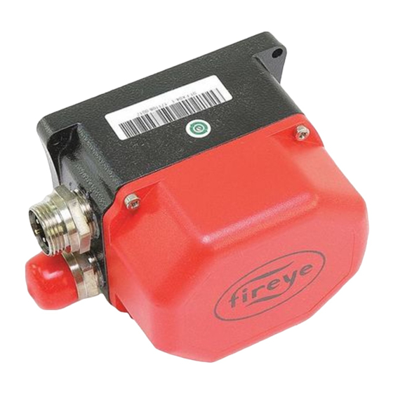
DESCRIPTION
This bulletin describes the installation and operating instructions for the FX series of servo motors.
These come in three sizes: FX04 (4Nm/3ft.-lb.), FX20 (20Nm/15ft.-lb.) and FX50 (50Nm/37ft.-lb.).
There are available in two baud rates: 56k for use with the NXF4000 or PPC4000 parallel positioning
system or 19.2k for general use with a PLC or other Modbus client. The FX04 size is also available in
a 38.4k baud rate for general use with a PLC or other Modbus client. Only the 56k model is approved
for use as part of a protective system (when used with the NXF4000 or PPC4000).
These servos are not compatible with or approved as replacements for the 945 series of
servos.
SAFETY INFORMATION
WARNING: When this equipment is mounted onto an appliance, all external
timers/controllers must be listed or recognized components and approved by
national certification agencies for the purpose for which they are used and
approved for use by a local authority who has jurisdiction.
WARNING – EXPLOSION HAZARD. DO NOT CONNECT OR DISCONNECT
WHEN ENERGIZED.
SYSTEM INFORMATION
The Fireye FX series servo motors are precision actuators designed to accurately position valves and
dampers. The servo motor interprets Modbus commands from an external control and uses a stepper
motor to drive to the commanded position.
The FX series servo motors offers maximum output torque ratings of 4Nm/3ft.-lb., 20Nm/15ft.-lb. or
50Nm/37ft.-lb. The fastest available travel time is 30 seconds for 90 degrees of rotation. The slowest
travel time available varies by size. Maximum rotation angle of the drive shaft is 100 degrees.
The servo is designed to be applied to drive any type of flow control valve or damper as long as the
output torque is suited to the application.
Before attempting to install, commission or operate this equipment all relevant sections of this document
must be read and fully understood, failure to follow them could damage the product or cause a hazardous
condition. If in doubt about any requirements consult the supplier.
© 2022 Carrier
Fireye FX Series
Modbus Controlled Actuator /Servo
Installation and Wiring
NEX-3001
January 18, 2022
1
Advertisement

Subscribe to Our Youtube Channel
Related Manuals for Fireye FX Series


Summary of Contents for Fireye FX Series
- Page 1 DESCRIPTION This bulletin describes the installation and operating instructions for the FX series of servo motors. These come in three sizes: FX04 (4Nm/3ft.-lb.), FX20 (20Nm/15ft.-lb.) and FX50 (50Nm/37ft.-lb.). There are available in two baud rates: 56k for use with the NXF4000 or PPC4000 parallel positioning system or 19.2k for general use with a PLC or other Modbus client.
- Page 2 These mounting and operating instructions are intended to give the knowledge which is necessary to carry out the mounting and adjustment of FX series servo motor safely and correctly. NOTE: The manufacturer of this equipment has a policy of continual product improvement and reserves the right to change the specification of the equipment and the contents of this manual without notice.
- Page 3 TECHNICAL DATA FX20 VERSIONS Fastest actuating time for 90° angle of rotation: 30 seconds Slowest actuating time for 90° angle of rotation: 368.4 seconds Nominal torque: 20Nm/15ft.-lb. Maximum angle of rotation: 100° Nominal voltage 24 VDC ± 10% Nominal power consumption: 15W nominal, 35W peak Angle of rotation limited by:...
-
Page 4: Ordering Information
ORDERING INFORMATION Servos for NXF4000/PPC4000 Parallel Positioning System (56k Baud) Bulletin Servo motor, 24 VDC operation, 4Nm, 3 ft.lb. torque, ½” NPT conduit threaded, FX04 minimum travel time of 30 seconds for 90°, 56k baud for NXF4000/PPC4000 Servo motor, 24 VDC operation, 4Nm, 3 ft.lb. -
Page 5: Safety Advice
SAFETY ADVICE Device safety The servo motor must only be used for purposes corresponding to its construction and within the values specified in the technical data. The installer should be satisfied that no potential hazards will be produced for any devices or machines involved as a result of the installation or commissioning. - Page 6 SERVO MOTOR DIAGRAM FX04 (FX04-1/FX04-119/FX04-138 with quick disconnects shown) diagram 90° FX20 (FX20-1/FX20-119 with quick disconnects shown) diagram 90° © 2022 Carrier ...
- Page 7 FX50 (FX50-1/FX50-119 with quick disconnects shown) diagram © 2022 Carrier 7 ...
- Page 8 DIMENSIONS FX04 dimensions © 2022 Carrier ...
- Page 9 FX20 dimensions © 2022 Carrier 9 ...
- Page 10 FX50 dimensions © 2022 Carrier ...
-
Page 11: Installation
The output drive shaft should be connected using a suitable arm, link, flexible coupling or D-hole couplings in order to assure a secure connection. The FX series servo can be mounted in any orientation. Ensure that the installation has future service accessibility. - Page 12 QUICK DISCONNECT FIELD WIRING Quick disconnect connectors are available in kit form for field wiring, 129-192. Fireye recommends cable part number 59-565 to be used for servo wiring. As shown above the cable strip length is specified at 30 mm (1.2 in) and each wire strip length is 7 mm (0.275 in).
- Page 13 Loosen the four housing cover screws and pull the cover up to remove. For the electrical installation of the FX series servo motor, use the prescribed cable type corresponding to the environmental conditions. Feed cables through suitable conduit and place the stripped ends of the leads into screw connection terminals and terminate.
- Page 14 FX04 terminal layout © 2022 Carrier ...
- Page 15 FX20 terminal layout © 2022 Carrier 15 ...
- Page 16 FX50 terminal layout ADJUSTMENTS/COMMISSIONING Adjustments Before the servo motor is opened or commissioned, the Safety Information and Safety Advice sections must be read. The cover must be removed to make the following adjustments. Unit address The servos use the Modbus communication protocol via RS485.
- Page 17 Manual movement The servo can be moved manually by using the two red buttons (location shown in Servo Motor Diagram section or on image below) whenever power is applied to the servo. There are separate buttons for CW and CCW movement.
- Page 18 MODBUS CONTROL SPECIFICS Read values Use function code 03 (read 4x or holding registers) for reading Modbus data. When reading values, any register valid for the write operation can be selected as the starting address. The length is what determines how much information is presented.
- Page 19 Error codes Sending a commanded position to the servo will erase/reset the present error code. It should be your normal process to read the servo before sending a new commanded position so that any detected errors will not be missed. In addition, once an error is detected, the servo will stop moving and release any braking feature.
- Page 20 Write registers Register Register (4x) FX04 Travel Time in Seconds FX20 Travel Time in Seconds FX50 Travel Time in Seconds 40002 368.4 202.1 40003 310.1 172.1 40004 267.7 148.2 40005 235.6 130.1 40006 210.3 116.4 40007 189.9 105.8...
- Page 21 40049 invalid 37.5 33.8 40050 invalid 36.8 33.5 40051 invalid 36.1 33.1 40052 invalid 35.4 32.7 40053 invalid 34.8 32.4 40054 invalid 34.2 32.1 40055 invalid 33.6 31.8 40056 invalid 33.0 31.4 ...
- Page 22 WARRANTIES FIREYE guarantees for one year from the date of installation or 18 months from date of manufacture of its products to replace or repair (Fireye’s option) any product or part thereof (except lamps and photocells) which is found defective in material or workmanship or which otherwise fails to conform to the description of the product on the face of its sales order.
Need help?
Do you have a question about the FX Series and is the answer not in the manual?
Questions and answers