Table of Contents
Advertisement
Quick Links
Advertisement
Table of Contents

Related Manuals for Colorjet AURAJET II Series


Summary of Contents for Colorjet AURAJET II Series
- Page 2 ColorJet group reserves all the rights to modify and revise this manual as per the company requirements without any prior notice. “No part of this document shall be reproduced or used by externals without prior permission of the ColorJet group”. The reference table is shown in the below table:...
-
Page 3: Table Of Contents
Table of Contents 1. About Document ................................3 Purpose ..................................3 Intended Audience ................................ 3 2. Printer Overview ................................4 Front View of the Printer .............................. 4 Back View of the Printer ............................... 5 3. Control Panel Layout ..............................7 4. - Page 4 Loading Calibration Parameter ..........................31 Setting Print Origin ..............................32 Setting Print Parameters ............................. 33 Changing Time and Language Password ........................33 Adding Jobs ................................. 35 Editing Job ................................... 37 Ripping and Printing ..............................38 Pausing and Canceling Printing ........................... 38 7.
-
Page 5: About Document
1. About Document Purpose The purpose of this document is to guide and educate the targeted audience about the Printer and its Printer Manager software so that they can easily and effectively handle as well as use it as per their requirements. Additionally, this document also provides step-wise instructions for handling various aspects of the printer and its related software with the help of graphical screens for easy and better understanding. -
Page 6: Printer Overview
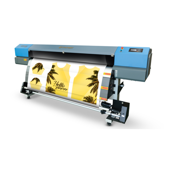
2. Printer Overview Front View of the Printer The front view of the printer is shown below: Fig 1: The Front View of the Printer Table 1: Different Parts of the Printer The Front View of the Printer 10. Glass Door Door Sensor LCD Panel 11. -
Page 7: Back View Of The Printer
Back View of the Printer The back view of the printer is shown below: Fig 2: The Back View of the Printer Table 2: Different Parts of the Printer The Back View of the Printer 18. Electrical view 19. Rear Pinch Lever Handle 20. - Page 8 The dimension of the printer is shown below: Fig 3: The Dimension of the Printer Page | 6 AuraJet Series II...
-
Page 9: Control Panel Layout
3. Control Panel Layout The control panel layout is shown below: Fig 4: The Operational Screen of the Printer The description of different operational buttons on the printer is given below: 1. Warning LED: Get ON if any warning occurs during the printing. 2. -
Page 10: Lcd Operations Flow Chart
4. LCD Operations Flow Chart Using the printer, several operations can be performed related to the printing viz. check nozzles, head cleaning, selecting media type, set origin, and more. Before performing the LCD operations, first you need to ready the printer for the use. -
Page 11: Main Menu Flow Chart
Main Menu Flow Chart The Main Menu flow diagram is shown below: Check Nozzles Main Menu Head Cleaning Adjustment Media Type Origin & Width Quality Head Parameter Disable Head Language System The Main Menu options are explained as follows: • Check Nozzles: Check the status of the print head nozzles. -
Page 12: Head Cleaning Menu
Head Cleaning Menu The head cleaning flow diagram is shown below: Head 1 Head Head Cleaning Clean Head Head 2 Selection Strong Both Normal Weak Fill ON / OFF Auto Clean Clean Strong Type Normal Weak Fill The Head Cleaning menu enables users to clean the print head using different modes viz. strong, normal, weak, and fill. -
Page 13: Media Type
Media Type The Media Type menu flow diagram is shown below: High Glossy Photopaper Media Type Vinyl Glossy Film Other 1 Other 2 Other 3 Let’s learn to select the media type from the Main Menu. Select the Media Type The Media Type option is available in the Main Menu. -
Page 14: Origin & Width Menu
Origin & Width Menu The Origin and Width menu flow diagram is shown below: Auto Measure Origin & Width Input X Origin = 10.02cm Input Width = 170.00cm Set Origin Margin = 0cm Using the Origin & Width menu, you can set the print origin by following the instructions given below. Set the Print Origin There are two ways to set the print origin viz. - Page 15 Step 4: Select the Set Origin option from the list, as shown below: Fig 9: Selecting the Set Origin Option Option 2 Follow these steps to set the print origin automatically: Step 1: Remove the left media clip to detect the full length of the media. Step 2: Select the Auto Measure option to set the print origin automatically (Refer to Fig 10).
-
Page 16: Quality Menu
Quality Menu Gradient The Quality menu flow diagram is shown below: Uniform Wave Advance Quality Feather Type Uniform Gradient Feather Level Tatting lace Step Before Print Flash Before Print Feather OFF Feather Weak Feather Normal Feather Strong Feather SupStrong Let’s learn to set the quality parameters. Setting the Quality Parameter The Quality option is used for enhancing the printing quality and controlling for some additional features of the printer. - Page 17 On selecting the Feather Type option, the follow screen appears, as shown below: Fig 12: Sub - Options of the Feather Type Option Note: Prefer to select the Gradient option for enhancing the printing quality. To specify the feather level, you have to select the Feather Level option from the given list of items (Refer to Fig 12). On selecting the Feather Level option, the following screen appears as shown below: Fig 13: Sub-Options Related to the Feather Level Option Note: Prefer to select the Feather Strong and Feather SupStrong (Feather Huge) along with Feather Intensity)
-
Page 18: Head Parameters Menu
Head Parameters Menu The Head Parameter menu flow diagram is shown below: K = 0 Head Parameter M = 0 Y = 0 C = 0 Disable Head Menu The Disable Head menu flow diagram is shown below: Disable Head 1 Disable Head Disable Head 2 Language Menu... -
Page 19: Getting Familiar With Printer Manager Interface
5. Getting Familiar with Printer Manager Interface The user interface of the Printer Manager software is shown below: Window Controls Quick Access Toolbar System Status Print Parameters Job Preview Job Information Job List Error Information Main Menu Fig 14: Displaying the Printer Manager The description of the Printer Manager window is given as below: •... -
Page 20: Printing
6. Printing Before issuing the Print command, you need to perform some operations and adjust printer settings viz. load media, nozzle testing, printer calibration, add jobs, set origin position, adjust print media, and more. Let’s discuss these operations one by one in the upcoming section. Loading Media Follow these steps to load the media in the printer: Step 1: Lift up the Media Lever, as shown below:... - Page 21 Step 4: Insert the supporting frame into the other side of media roller till it is firm enough. After that, tighten the fixed bolt, as shown below: Fig 16: Inserting the Media Roll Step 5: Unwind the media roll to reach near the platen and hold it. Step 6: Insert the taken out media between the platform and the pinch roller.
- Page 22 Step 10: Pull the enough media so that it reaches to the Take Up brackets (or let the media down by issuing the Print command). Step 11: Fix an empty Core over the Core Holder between the Take Up brackets. Note: Align the Core Holder brackets as per the media position.
-
Page 23: Nozzle Testing
Note: The Forward / Reverse button should be in the center position for working in auto mode. Step 14: Move the media forward so that it rolls easily over the Core. Now, the media gets loaded. Note: Before issuing the Print command, verify the following things: •... -
Page 24: Print Head Calibration
Print Head Calibration Print head is a critical part of the printer that should be calibrated to ensure high print quality. Follow these steps to calibrate the print heads: Step 1: Press the Menu button on the printer. Step 2: Select the Adjustment option from the menu list, as shown below: Fig 22: Selecting the Adjustment Option On selecting the Adjustment option, it’s related sub-options appear on the screen viz. - Page 25 The Feed Adjust test result is shown in the image below: Fig 23: The Feed Adjust Test Result To perform the Feed Adjust test, you should first select the media type according to which the calibration has been done. From the above figure, you get the accurate feed adjust correction value. The correction value is either positive or negative.
- Page 26 Now, the media gets selected and you can easily calibrate the printer accordingly. Performing the Feed Adjust Test Follow these steps to perform the Feed Adjust test: 1. Press the Menu button available on the printer. 2. Select the Adjustment option from the menu list (Refer to Fig 24). It’s related sub-options viz. Feed Calibration and Bi-Dir appears on the screen as shown below: Fig 26: Selecting the Feed Adjust Option 3.
- Page 27 5. Select the Print option from the above screen (Refer to Fig 28). Now, the Feed Adjust test result will print again on the media. 6. Select the Value option from the Feed Calibration screen (Refer to Fig 28). The Feed Adjust Correction Value screen appears, as shown below: Fig 29: Displaying the Feed Adjust Value Screen 7.
- Page 28 In the above figure, the Bi-Dir test result has been shown. If you observe the result, you can find that the Bi-Dir test result is correct at the “0” position. Thus, you need to adjust the Bi-Dir value by adding 0 in the current value. Follow these steps to perform the Bi-Dir test for print head calibration: 1.
-
Page 29: System Settings
5. Select the Print (High) option to check the result of the Bi-Dir test. Now, the Bi-Dir test result will print again on the media. 6. Select the Value (High) option from the above screen (Refer to Fig 33). The Bi-Dir Correction screen appears as shown below: Fig 34: The Bi-Dir Correction Screen 7. - Page 30 The Setting window appears with the default selection of the Printer tab, as shown below: Fig 36: Displaying the Setting Window Page | 28 AuraJet Series II...
- Page 31 The Preference tab is shown in the image below: Fig 37: Displaying the Preference Tab Page | 29 AuraJet Series II...
-
Page 32: Saving Calibration Parameter
Saving Calibration Parameter Follow these steps to save calibration parameter: Step 1: Click on the Main Menu→Setting→Save Calibration Parameter path. The Save As window appears on the screen. Step 2: Navigate to the location where you want to store the calibration parameter details file (Refer to Fig 38). Step 3: After navigating to the location, click on the Save to save the file as shown below: Fig 38: Displaying the Save As Window Now, all the settings get saved in a bin file and user can use and load these settings whenever required. -
Page 33: Loading Calibration Parameter
Loading Calibration Parameter The Load Calibration Parameter option is used to load any previously saved calibration parameter details. Follow these steps to load previously saved calibration parameter settings: Step 1: Click on the Main Menu→Setting→Load Calibration Parameter path. The Open window appears as shown below: Fig 39: Displaying the Open Window Step 2: Navigate to the location where the calibration parameter details file is stored. -
Page 34: Setting Print Origin
Setting Print Origin Print origin sets the print starting point with the left limit switch as the reference point. It can be set by two ways; moving and positioning the carriage and typing the offset value directly in the given field. Follow these steps to change the print origin: Step 1: Move the carriage at the position from where you want to start the printing by clicking on the left and right buttons on the Quick Access Toolbar, as shown below:... -
Page 35: Setting Print Parameters
Setting Print Parameters Using the Printer Manager, you can manually change print preferences as per the printing requirements such as print origin, printing speed, no of steps, and more as shown below: Fig 43: Displaying the Print Parameters • Origin X: Directly enter the print origin value. •... - Page 36 The Password window appears on the screen as shown below: Fig 45: The Password Window Step 2: Set values in the Time Password and Language Password fields as per the requirements (Refer to Fig 45). Step 3: After feeding the passwords, click on the Set button in front of both the options (Refer to Fig 45). Step 4: Click on the Exit button to close the Password window (Refer to Fig 45).
-
Page 37: Adding Jobs
Adding Jobs There are two ways to add jobs in the Job List area viz. the Add Job button and right click on the Job List area. Let’s discuss both the ways one by one. Follow these steps to add jobs in the Job List area: Step 1: Click on the Add Job button on the Quick Access Toolbar, as shown below: Fig 46: Clicking the Add Job Button The Open window appears on the screen. - Page 38 Now, the selected image appears in the Job List area, as shown below: Fig 48: Displaying the Job at the Job List Area Once a file has been added its information such as file path, size, resolution, and number of passes can be viewed in the Job Information area.
-
Page 39: Editing Job
Editing Job Follow these steps to edit the selected job: Step 1: Select the job which details you want to edit from the Job List area. Step 2: Right-click on the selected job. The context menu appears on the screen. Step 3: Select on the Edit option from the context menu, as shown below: Fig 50: Displaying the Context Menu The Edit Job Form appears with the list of options viz. -
Page 40: Ripping And Printing
Ripping and Printing Ripping is an independent process which converts a raw image file into the machine readable format and get the file ready for printing. The Rip software supports the tiff, jpeg, eps, psd, bmp file formats. After ripping the image file, the output file will be in “.prt”... -
Page 41: Maintenance
7. Maintenance Print Head Maintenance Print Head is an important and delicate part of the printer. Thus, it must be handled with care to ensure the long life of the print heads. For print head maintenance, the following instructions should be taken care: •... -
Page 42: Daily Maintenance
The Head Cleaning options screen appears on the screen, as shown below: Fig 56: The Head Cleaning Options Screen Step 3: Select the Weak option from the available list. The printer starts cleaning the heads for maintaining the printing quality. Note: For the print head cleaning, the Weak option is always recommended to avoid the ink wastage. -
Page 43: Troubleshooting
8. Troubleshooting Printer Not Initializing • Encoder scale is having ink stains (print shows vertical color bands) • Encoder sensor is not cleaned • Initialization of the wiper and capping station is incomplete or stuck Printer Manager Not Showing “READY” •... - Page 44 Heaters Not Working • Check if inlet power cord and supply power are connected • Check the set temperature in the controller Head Not Firing • Perform nozzle test and clean heads if required • Check if any air lock or no ink in the head pipes •...
-
Page 45: Error Handling
9. Error Handling Error 1: “FTA 12 Head INITS1 Fail” Reason: Restart the print without any time delay. Solution: After Switch Off, wait for 10 sec. and then restart the printer. The FTA 12 Head INITS1 Fail screen is shown in the image below: Fig 57: Displaying Error 1 Error 2: “FTA 249 Paper Jam in Horizontal”... - Page 46 The Pause (Cover Up) screen is shown in the image below: Fig 59: Displaying Error3 Error 4: “Pause (Media Lack)” Reason: Media end sensor detects absence of media. Solution: Block the sensor temporarily and resume the print. Further, load new media roll. The Pause (Media Lack) screen is shown in the image below: Fig 60: Displaying Error 4 Page | 44...
- Page 48 For Any Query Please Contact Us www.colorjetgroup.com Call on +91-120-4548195 Email on info@colorjetgroup.com For Ink Enquiry:- sales@colorjetgroup.com For Support:- support@colorjetgroup.com...
Need help?
Do you have a question about the AURAJET II Series and is the answer not in the manual?
Questions and answers