Table of Contents
Advertisement
Quick Links
Advertisement
Table of Contents
Troubleshooting

Related Manuals for Xcel-Arc RAZORWELD 205


Summary of Contents for Xcel-Arc RAZORWELD 205
- Page 1 RAZORWELD 205 SMART SET MIG/TIG/STICK WELDER Operating Manual | XA-MIG205SS Weld Razor YEAR YEAR M AC H I N E P RO DU CT WARRANTY WARRANTY STICK Please read and understand this instruction manual carefully before the installation and operation of this equipment.
-
Page 2: Warranty
Secondly they provide a customer support service that is second to none, thus ensuring our customers have confidence that they will be well satisfied both now and in the future. Xcel-Arc welders and plasma cutters are manufactured to be compliant with - AS/NZ 60974-1, guaranteeing you electrical safety and performance. WARRANTY •... -
Page 3: Table Of Contents
Razor Weld CONTENTS WARRANTY SAFETY RAZORWELD MIG205SS FEATURES MACHINE PARTS LAYOUT INSTALLATION SET UP FOR MMA (STICK) WELDING MMA(STICK) WELDING GUIDE GAS INSTALLATION & SET UP - MIG WIRE INSTALLATION AND SET UP GUIDE MIG WELDING GUIDE INSTALLATION SET UP OF THE SPOOL GUN INSTALLATION SET UP FOR DC TIG WELDING TIG WELDING GUIDE XA24 MIG TORCH &... -
Page 4: Safety
SAFETY Welding and cutting equipment can be dangerous to both the operator and people in or near the surrounding working area, if the equipment is not correctly operated. Equipment must only be used under the strict and comprehensive observance of all relevant safety regulations. Read and understand this instruction manual carefully before the installation and operation of this equipment. - Page 5 Razor Weld SAFETY Fire hazard. Welding/cutting on closed containers, such as tanks,drums, or pipes, can cause them to explode. Flying sparks from the welding/cutting arc, hot work piece, and hot equipment can cause fires and burns. Accidental contact of electrode to metal objects can cause sparks, explosion, overheating, or fire.
- Page 6 SAFETY CAUTION 1. Working Environment. The environment in which this welding/cutting equipment is installed must be free of grinding dust, corrosive chemicals, flammable gas or materials etc, and at no more than maximum of 80% humidity. ii. When using the machine outdoors protect the machine from direct sun light, rain water and snow etc; the temperature of working environment should be maintained within -10°C to +40°C.
-
Page 7: Razorweld Mig205Ss Features
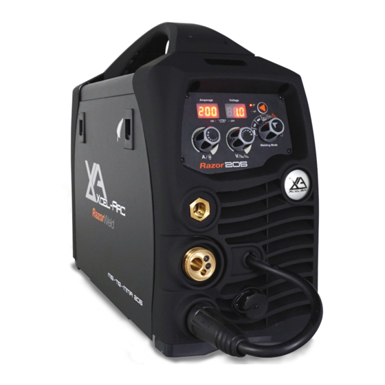
Razor Weld RAZORWELD MIG205SS FEATURES MIG/TIG/STICK - 200 Amp DC Inverter Welder Welds: Steels, Stainless, Cast Iron, Bronze, Aluminium, Copper With Smart Set™ Operating System Features ■ Latest 40KHz IGBT inverter frequency technology ■ MIG/MAG with Gas and Gasless capabilty - Unique Smart Set™... -
Page 8: Machine Parts Layout
MACHINE PARTS LAYOUT FRONT PANEL LAYOUT 1. Digital Amperage & Wire Speed Display 2. Digital Volt Meter/ Arc Force / Downslope Display 3. VRD LED 4. Wire Speed / Ampearge Adjustment Knob 5. Voltage /Arc Force / Downslope Adjustment Knob 6. - Page 9 Razor Weld MACHINE PARTS LAYOUT MMA Function - Front Panel Description 1. Arc Force Display 2. Amperage Display 3. Amperage Control 4. Arc Force Control 5. MMA Function Select TIG Function - Front Panel Description 1. Downslope Time Display 2. Amperage Display 3.
-
Page 10: Installation Set Up For Mma (Stick) Welding
INSTALLATION SET UP FOR MMA (STICK) WELDING (1) Turn the power source on and select the MMA function with the Tig/MMA/Mig selector switch. (2) Connection of Output Cables Two sockets are available on this welding machine. For MMA welding the electrode holder is shown be connected to the negative socket, while the earth lead (work piece) is connected to the positive socket, this is known as DC- polarity. -
Page 11: Mma(Stick) Welding Guide
Razor Weld MMA(STICK) WELDING GUIDE MMA (Manual Metal Arc) Welding One of the most common types of arc welding is manual metal arc welding (MMA) or stick welding. An electric current is used to strike an arc between the base material and a consumable electrode rod or ‘stick’. The electrode rod is made of a material that is compatible with the base material being welded and is covered with a flux that gives off gaseous vapours that serve as a shielding gas and providing a layer of slag, both of which protect the weld area from atmospheric contamination. - Page 12 MMA(STICK) WELDING GUIDE MMA (Stick) Welding Fundamentals Electrode Selection As a general rule, the selection of an electrode is straight forward,in that it is only a matter of selecting an electrode of similar composition to the parent metal. However, for some metals there is a choice of several electrodes, each of which has particular properties to suit specific classes of work.
-
Page 13: Gas Installation & Set Up - Mig
Razor Weld GAS INSTALLATION & SET UP - MIG (1) Select Standard using the Standard/Spool Gun selector switch. (2) Insert the earth cable plug into the negative socket on the front of the machine and tighten it. (3) Plug the welding torch into the Euro Mig torch connection socket on the front panel, and tighten it. IMPORTANT : When connecting the torch be sure to tighten the connection. - Page 14 GAS INSTALLATION & SET UP - MIG Align the wire into the groove of the drive roller and close down the top roller making sure the wire is in the groove of the bottom drive roller, lock the pressure arm into place. Apply a medium amount of pressure to the drive roller (10) Remove the gas nozzle and contact tip from the torch neck, (11) Press and hold the inch button to feed the wire through to the torch neck, release the inch button when the wire...
- Page 15 Razor Weld WIRE FEED ROLLER SELECTION Wire Feed Roller Selection The importance of smooth consistent wire feeding during MIG welding cannot be emphasized enough. Simply put the smoother the wire feed then the better the welding will be. Feed rollers or drive rollers are used to feed the wire mechanically along the length of the welding gun. Feed rollers are designed to be used for certain types of welding wire and they have different types of grooves machined in them to accommodate the different types of wire.
-
Page 16: Wire Installation And
WIRE INSTALLATION AND SET UP GUIDE Again the importance of smooth consistent wire feeding during MIG welding cannot be emphasized enough. The correct installation of the wire spool and the wire into the wire feed unit is critical to achieving an even and consistent wire feed. - Page 17 Razor Weld MIG TORCH LINER INSTALLATION MIGTorch Liner Installation 1. Lay the torch out straight on the ground and remove the front end parts (1) Lay the torch out straight on the ground and remove the front end parts 2. Remove the liner retaining nut. (2) Remove the liner retaining nut.
- Page 18 MIG TORCH LINER TYPES Mig Torch Liner Types Mig Torch Liners The liner is both one of the simplest and most important components of a MIG gun. Its sole purpose is to guide the welding wire from the wire feeder, through the gun cable and up to the contact tip. Steel Liners Most MIG gun liners are made from coiled steel wire also known as piano wire, which provides the liner with good during operational use.
- Page 19 Razor Weld TORCH & WIRE FEED SET UP FOR ALUMINIUM WIRE (1) Lay the torch out straight on the ground and remove the front end parts (2) Remove the liner retaining nut. (3) Carefully pull the liner out of the torch cable assembly (4) Select a PA or liner, carefully and slowly feed the liner in short forward movements down the cable assembly all the way through and out the torch neck end.
- Page 20 TORCH & WIRE FEED SET UP FOR ALUMINIUM WIRE Continued... (10) Loosen off the inlet guide tube retaining screw (11) Remove the inlet guide tube from the front end machine euro connector using long nose pliers. (12) Carefully feed the extended PA liner section into the inlet guide tube hole of the machine euro connector (13) Feed the extended PA liner all the way up and over the drive roller (14) Tighten the torch euro connection to the machine euro connector...
-
Page 21: Mig Welding Guide
Razor Weld MIG WELDING GUIDE MIG (Metal Inert Gas) Welding Definition of MIG Welding - MIG (metal inert gas) welding also known as GMAW (gas metal arc welding) or MAG (metal active gas welding), is a semi-automatic or automatic arc welding process in which a continuous and consumable wire electrode and a shielding gas are fed through a welding gun. - Page 22 MIG WELDING GUIDE MIG (Metal Inert Gas) Welding Short Circuit Transfer - Short circuit transfer is the most common used method whereby the wire electrode is fed continuously down the welding torch through to and exiting the contact tip. The wire touches the work piece and causes a short circuit the wire heats up and begins to form a molten bead, the bead separates from the end of the wire and forms a droplet that is transferred into the weld pool.
- Page 23 Razor Weld MIG WELDING GUIDE Basic MIG Welding Good weld quality and weld profile depends on gun angle, direction of travel, electrode extension (stick out), travel speed, thickness of base metal, wire feed speed (amperage) and arc voltage. To follow are some basic guides to assist with your setup. Gun Position - Travel Direction, Work Angle Gun position or technique usually refers to how the wire is directed at the base metal, the angle and travel direction chosen.
- Page 24 MIG WELDING GUIDE Travel Angle Travel angle is the right to left angle relative to the direction of welding. A travel angle of 5°- 15° is ideal and produces a good level of control over the weld pool. A travel angle greater that 20° will give an unstable arc condition with poor weld metal transfer, less penetration, high levels of spatter, poor gas shield and poor quality finished weld.
- Page 25 Razor Weld MIG WELDING GUIDE Travel Speed Travel speed is the rate that the gun is moved along the weld joint and is usually measured in mm per minute. Travel speeds can vary depending on conditions and the welders skill and is limited to the welders ability to control the weld pool. Push technique allows faster travel speeds than Drag technique.
- Page 26 MIG WELDING GUIDE Wire types and sizes Use the correct wire type for the base metal being welded. Use stainless steel wire for stainless steel, aluminium wires for aluminium and steel wires for steel. Use a smaller diameter wire for thin base metals. For thicker materials use a larger wire diameter and larger machine, check the recommended welding capability of you machine.
-
Page 27: Installation Set Up Of The Spool Gun
Razor Weld INSTALLATION SET UP OF THE SPOOL GUN Select Spool Gun using the Standard/Spool Gun selector switch. Connect the Spool Gun to the Euro Mig torch connection socket on the front panel, and tighten it. IMPORTANT : When connecting the torch be sure to tighten the connection. A loose connection can result in the connector arcing and damaging the machine and gun connector. - Page 28 INSTALLATION SET UP OF THE SPOOL GUN (11) Unclip and swing open the wire feed housing cover to expose the wire feed mechanism. (12) Unclip and swing back the wire tension swing arm. Check the that the correct drive roller is installed. (13) Carefully feed the wire through the drive roller into the inlet guide tube.
-
Page 29: Installation Set Up For Dc Tig Welding
Razor Weld INSTALLATION SET UP FOR DC TIG WELDING (1) Connect the Tig torch to the Euro connection on the front of the machine and tighten it. IMPORTANT : When connecting the torch be sure to tighten the connection (2) Insert the earth cable plug into the Positive socket on the front of the machine and tighten it. (3) Insert the weld power cable plug into the Negative socket on the front of the machine and tighten it. - Page 30 LIFT ARC DC TIG OPERATION Lift Arc ignition allows the arc to be started easily in DC Tig by simply touching the tungsten to the work piece and lifting it up to start the arc. This prevents the tungsten tip sticking to the work piece and breaking the tip from the tungsten electrode.
-
Page 31: Tig Welding Guide
Razor Weld TIG WELDING GUIDE DC TIG Welding The DC power source uses what is known as DC (direct current) in which the main elec- trical component known as electrons flow in only one direction from the negative pole (terminal) to the positive pole (terminal). In the DC electrical circuit there is an electrical principle at work which should always be taken into account when using any DC circuit. - Page 32 TIG WELDING GUIDE DC Pulse TIG Welding Pulse TIG welding is when the current output (amperage) changes between high and low current. Electronics within the welding machine create the pulse cycle. Welding is done during the high-amperage interval (this high amperage is referred to as peak current). During the low amperage period, the arc is maintained but the current output of the arc is reduced (this low amperage is referred to as base current).
- Page 33 Razor Weld TIG WELDING GUIDE TIG Welding Fusion Technique Manual TIG welding is often considered the most difficult of all the welding process- es. Because the welder must maintain a short arc length, great care and skill are re- quired to prevent contact between the electrode and the workpiece. Similar to Oxy- gen Acetylene torch welding, Tig welding normally requires two hands and in most instances requires the welder to manually feed a filler wire into the weld pool with one hand while manipulating the welding torch in the other.
- Page 34 DC TIG WELDING GUIDE Tungsten Electrodes Tungsten is a rare metallic element used for manufacturing TIG welding electrodes. The TIG process relies on tungsten’s hardness and high-temperature resistance to carry the welding current to the arc. Tungsten has the highest melting point of any metal, 3,410 degrees Celsius.
- Page 35 Razor Weld DC TIG WELDING GUIDE Tungsten Preparation wheels when grinding and cutting. While tungsten is a very hard material, the surface of a Always use DIAMOND diamond wheel is harder, and this makes for smooth grinding. Grinding without diamond wheels, such as aluminium oxide wheels, can lead to jagged edges, imperfections, or poor surface finishes not visible to the eye that will contrib- ute to weld inconsistency and weld defects.
-
Page 36: Xa24 Mig Torch & Spares
XA24 MIG TORCH & SPARES XA24 MIG TORCH XA24 MIG TORCH Suregrip Suregrip™ ™ Series Series 250A AIR COOLED MIG WELDING TORCH Rating:250A CO 220A mixed gas EN60974-7 @ 60% duty cycle. 0.8 to 1.2mm wires Front end parts shown on opposite page Liners shown on opposite page... - Page 37 Razor Weld XA24 MIG TORCH & SPARES Suregrip Suregrip™ ™ Series Series XA24 MIG TORCH CONSUMABLES XA24 MIG TORCH CONSUMABLES Front end consumables XA24 Contact Tips Part Number Description XA2504-06 Contact Tip ECu 0.6mm D6 M6 x 28mm XA2504-08 Contact Tip ECu 0.8mm D8 M6 x 28mm XA2504-09 Contact Tip ECu 0.9mm D8 M6 x 28mm XA2504-10...
-
Page 38: Xasp24 Spool Gun & Spares
XASP24 SPOOL GUN & SPARES Suregrip Suregrip™ ™ Series Series 220A AIR COOLED SPOOL ON GUN MIG WELDING TORCH Rating:220A CO 200A mixed gas EN60974-7 @ 60% duty cycle. 0.8 to 1.2mm wires Wear parts next page Torch Model Part Number Description XASP24-24-P1-60ER XA Suregrip Spool Gun 220A x 6m, 1K Pot, 24V Motor... - Page 39 Razor Weld XASP24 SPOOL GUN & SPARES Suregrip Suregrip™ ™ Series Series XASP24 MIG TORCH CONSUMABLES XASP24 MIG TORCH CONSUMABLES Front end consumables XA24 Contact Tips Part Number Description XA2504-06 Contact Tip ECu 0.6mm D6 M6 x 28mm XA2504-08 Contact Tip ECu 0.8mm D8 M6 x 28mm XA2504-09 Contact Tip ECu 0.9mm D8 M6 x 28mm XA2504-10...
-
Page 40: Xa26 Tig Torch & Spares
XA26 TIG TORCH & SPARES XA26 TIG TORCH XA26 TIG TORCH Suregrip Suregrip™ ™ Series Series 180AMP AIR COOLED XcelArc Rating: 180A DC, 125A AC @35% duty cycle. Wear Parts Identification Next Page Wear Parts Identification Next Page Euro Connection for XA26-12S1EG Torch Used on MIG 250DRZ &... - Page 41 Razor Weld XA26 TIG TORCH & SPARES Standard Front End Parts 18CG 10N22 Collet 1.0mm 10N30 Collet Body 1.0mm 10N50 10N49L Long Alumina Nozzle Ø 8mm Alumina Nozzle Ø 6mm 10N23 Collet 1.6mm 10N31 Collet Body 1.6mm 10N49 10N48L Long Alumina Nozzle Ø 10mm #6L Alumina Nozzle Ø...
-
Page 42: Gas Flow Regulators - Sheilding Gases Gas Flow Rates
GAS FLOW REGULATORS - SHEILDING GASES GAS FLOW RATES GAS FLOW REGULATORS The job of the gas flow regulator is to reduce the bottle pressure gas down to a lower pressure and deliver it at a constant flow. This constant flow of gas is usually fed through the welding machine where it is controlled by a solenoid valve, operated when the torch trigger is pulled. -
Page 43: Mma (Stick) Welding Trouble Shooting
MMA (STICK) WELDING TROUBLE Razor Weld SHOOTING The following chart addresses some of the common problems of MMA welding. In all cases of equipment malfunction, the manufacturer’s recommendations should be strictly adhered to and followed. 1: No arc Possible Reason Suggested Remedy Incomplete welding circuit Check earth lead is connected. -
Page 44: Mig Welding Trouble Shooting
MIG WELDING TROUBLE SHOOTING The following chart addresses some of the common problems of MIG welding. In all cases of equipment malfunction, the manufacturer’s recommendations should be strictly adhered to and followed. 1: Excessive Spatter Possible Reason Suggested Remedy Select lower wire feed speed Wire feed speed set too high Select a lower voltage setting Voltage too high... - Page 45 Razor Weld MIG WIRE FEED TROUBLE SHOOTING The following chart addresses some of the common WIRE FEED problems during MIG welding. In all cases of equipment malfunction, the manufacturer’s recommendations should be strictly adhered to and followed. 1: Inconsistent / interrupted wire feed Possible Reason Suggested Remedy Select the correct polarity for the wire being used - see machine setup guide...
-
Page 46: Tig Welding Trouble Shooting
TIG WELDING TROUBLE SHOOTING The following chart addresses some of the common problems of TIG welding. In all cases of equipment malfunction, the manufacturer’s recommendations should be strictly adhered to and followed. 1: Tungsten burning away quickly Possible Reason Suggested Remedy Incorrect Gas Check that pure Argon is being used No gas... - Page 47 Razor Weld TIG WELDING TROUBLE SHOOTING 6: HF present but no welding power Possible Reason Suggested Remedy Incomplete welding circuit Check earth lead is connected. Check all cable connections. If using a water cooled torch check that the power cable is not separated. No gas Check the gas is connected and cylinder valve open, check hoses, gas valve and torch are not restricted.
-
Page 48: Warranty Terms
WARRANTY TERMS ESSETI New Zealand Limited (‘us’, ‘we’) warrants that the products bearing the brand names ESSETI, XCEL-ARC, RAZORWELD, RAZORCUT, JASIC, VIPER, T&R, XCEL-GAS, Otos, Servore, TECNA & HIT-8SS supplied by us and purchased by you from an Authorised ESSETI (NZ) Ltd. Distributor are free of Material and Faulty Workmanship Defects except for those products listed under ‘Warranty Exclusions’... - Page 49 Razor Weld WARRANTY TERMS WARRANTY / RETURNS / EXCHANGES Our Warranty Returns Policy recognises all and any rights you have under New Zealand Consumer Law and other relevant laws. You shall inspect the goods on delivery and shall within seven (7) days of delivery (time being of the essence) notify the Esseti NZ Ltd. Authorised Distributor from whom you purchased the goods of any alleged defect, shortage in quantity, damage or failure to comply with the description or quote.
- Page 50 Tungsten Electrodes, Collet, Collet Body, Alumina Nozzle, Torch Head, Torch Head water Cooled, Torch Head Flexible, Back Caps, Gas Lens, Torch Handle, Cup Gasket, Torch Body Gas Valve, O-ring, All XCEL-ARC TIG Welding Rods, All XCEL-ARC / Magmaweld Electrodes, Arc Leads, Welding Cable, Electrode Holder, Earth Clamps •...
-
Page 51: Notes
Razor Weld NOTES | 51 RAZORWELD™205SS MIG/TIG/STICK Welder Manual... - Page 52 Razor Weld New Zealand Limited Esseti New Zealand Limited PO Box 4189, Palmerston North - 4442 Phone: 06 355 1103 Fax: (06) 354 2437 Email: sales@esseti.co.nz www.esseti.co.nz Xcel-Arc © Esseti NZ LTD - 2021...
Need help?
Do you have a question about the RAZORWELD 205 and is the answer not in the manual?
Questions and answers