
Related Manuals for Xcel-Arc VIPER Plasma CUT30


Summary of Contents for Xcel-Arc VIPER Plasma CUT30
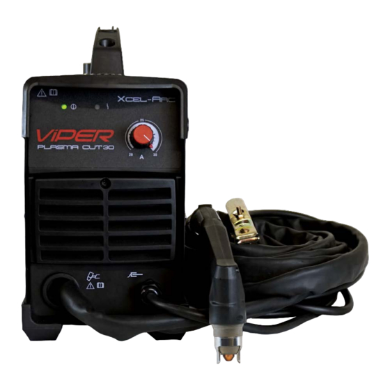
- Page 1 PLASMA CUT3O XA-CUT30V | Operating Manual YEAR M AC H IN E WARRANTY Please read and understand this instruction manual carefully before the installation and operation of this equipment. © Xcel-Arc 2020...
-
Page 2: Warranty
PLASMA CUT30 Thank you for choosing to purchase this VIPER Plasma Cutting Machine. We are proud of our range of welding & cutting equipment that has a proven track record of innovation, per- formance and reliability. Our product range represents the latest developments in inverter technology put together by our professional team of highly skilled engineers. -
Page 3: Table Of Contents
PLASMA CUT30 CONTENTS PAGE Warranty Safety - Cautions Air Plasma Cutting Technology Technical Data, Product Information Machine Layout & Descriptions Set Up and Operating Procedure 10-11 Plasma Cutting Procedure & Techniques 12-14 SC40 Plasma Torch Parts Breakdown Trouble Shooting Machine Warranty 17-18 Notes REGISTER YOUR MACHINE ONLINE TO RECEIVE AN... -
Page 4: Safety - Cautions
SAFETY BEFORE INSTALLING, OPERATING OR CARRYING OUT IMPORTANT: MAINTENANCE ON THE PLASMA CUTTER, READ THE CONTENTS OF THIS MANUAL CAREFULLY, WHICH MUST BE STORED IN A PLACE FAMILIAR TO ALL USERS FOR THE ENTIRE OPERATIVE LIFE-SPAN OF THE MACHINE. PAY PARTICULAR ATTENTION TO THE SAFETY RULES. THIS EQUIPMENT MUST BE USED SOLELY FOR PLASMA CUTTING. - Page 5 Fire hazard. Plasma cutting on closed containers, such as tanks,drums, or pipes, can cause them to explode. Flying sparks from the welding arc, hot work piece, and hot equipment can cause fires and burns. Accidental contact of electrode to metal objects can cause sparks, ex- plosion, overheating, or fire.
- Page 6 CAUTION 1. Working Environment. 1.1 The environment in which this Plasma Cutter equipment is installed must be free of grinding dust, corrosive chemicals, flammable gas or materials etc, and at no more than maximum of 80% humidity. 1.2 When using the machine outdoors protect the machine from direct sun light, rain water and snow etc; the temperature of working environment should be maintained within -10°C to +40°C.
-
Page 7: Air Plasma Cutting Technology
AIR PLASMA CUTTING TECHNOLOGY Plasma cutters work by passing an electric arc through a gas that is passing through a constricted opening. The gas can be air, nitrogen, argon, oxygen. etc. The electric arc elevates the temperature of the gas to the point that it enters a 4th state of matter. -
Page 8: Technical Data, Product Information
Designed to meet the needs of the price conscious non-commercial user without compromising on quality, this ma- chine is as reliable and robust as you would expect a machine bearing the Xcel-Arc name to be. The VIPER CUT30 produces a high tem- perature plasma stream enabling efficient cutting of all electrically conductive materials including steel, cast Iron, stainless steel, copper, aluminium brass etc. -
Page 9: Machine Layout & Descriptions
Front & Rear Panel Layout PLASMA CUT30 Front Panel Layout Rear Panel Layout (1) Mains Power LED (2) Over Current - Thermal Overload LED a. Abnormal or over current supply - LED ON b. Overheating of the machine - LED ON (3) Amperage Control Dial (4) Torch connection (5) Output connector, connect to the work piece... -
Page 10: Set Up And Operating Procedure
PLASMA CUT30 Set Up Procedure for PLASMA Cutting (1) Connect the earth clamp to the work piece. (2) Connect the air supply to the air connection located at the rear of the machine. (3) Set the Air Pressure at 5-6 Bar using the pressure adjusting knob. (4) Connect the machine to the correct power supply and switch on the machine using the on/off switch located at the rear of the machine. - Page 11 Operating Procedure for PLASMA Cutting PLASMA CUT30 Operating procedure using the Stand Off Guide mounted to SC40 torch. The feet of the standoff guide are placed on the cutting surface. This maintains an optimal 2mm standoff distance between the plasma cutting tip and the work, this is especially suitable if your hands are unsteady, or if you wish to use a straight edge guide or pattern guide.
-
Page 12: Plasma Cutting Procedure & Techniques
Operating Procedure & Techniques for PLASMA Cutting PLASMA CUT30 ● Amperage Standard rule of thumb is the thicker the material the more amperage required. On thick material, set the machine to full output and vary your travel speed. On thinner material, you need to turn down the amperage and change to a lower-amperage tip to maintain a narrow kerf. - Page 13 Operating Procedure & Techniques for PLASMA Cutting PLASMA CUT30 ● Air pressure and volume Air pressure, flow rate and air quality are critical to quality plasma cutting and consumable life span. The required air pressure and volume can vary from model to model and the manufacturer will provide the specs. The volume capacity of your compressor is important, if you have a small compressor with exactly the same l/min rating as the plasma, then the compressor will run continuously when you are plasma cutting, a compressor with a l/min rating slightly higher than the plasma would be more adequate.
- Page 14 Operating Procedure & Techniques for PLASMA Cutting PLASMA CUT30 ● Piercing Hold the torch at an angle to the work piece, When sparks are exiting from the bottom of When the pierce is complete, proceed with pull the trigger to start the arc and slowly the work piece, the arc has pierced through cutting.
-
Page 15: Sc40 Plasma Torch Parts Breakdown
PLASMA CUTTING TORCH SC30 SC30 Plasma Torch & Spares Plasma Torch & Spares PLASMA CUT30 Air Cooled 30 Amp Surecut SC40 Surecut SC40 Rating: 40A Air/N Gas, @ 60% duty cycle. For use on VIPER CUT30 Technical Data Max Current Gas Pressure 4.5-5.0 Bar (65-75psi) Duty Cycle Gas Flow... -
Page 16: Trouble Shooting
PLASMA CUT30 Trouble Shooting A. The cutting torch fails to ignite the arc, when torch trigger is pressed. 1. Gas pressure too high or too low, check and adjust gas pressure to 5bar/70psi. 2. The shield cup is not installed correctly, turn off the power source, install and screw it down properly, then turn on the power source. -
Page 17: Machine Warranty
ESSETI New Zealand Limited (‘us’, ‘we’) warrants that the products bearing the brand names ESSETI, XCEL-ARC, RAZORWELD, RAZORCUT, JASIC, VIPER, T&R, XCEL-GAS, Otos, Servore, TECNA & HIT-8SS supplied by us and purchased by you from an Authorised ESSETI (NZ) Ltd. Distributor are free of Material and Faulty Workmanship Defects except for those products listed under ‘Warranty Exclusions’... - Page 18 Tungsten Electrodes, Collet, Collet Body, Alumina Nozzle, Torch Head, Torch Head water Cooled, Torch Head Flexible, Back Caps, Gas Lens, Torch Handle, Cup Gasket, Torch Body Gas Valve, O-ring, All XCEL-ARC TIG Welding Rods, All XCEL-ARC / Magmaweld Electrodes, Arc Leads, Welding Cable, Electrode Holder, Earth Clamps •...
-
Page 19: Notes
NOTES... - Page 20 New Zealand Limited Esseti New Zealand Limited PO Box 4189, Palmerston North - 4442 Phone: 06 355 1103 Fax: (06) 354 2437 Email: sales@esseti.co.nz www.esseti.co.nz Xcel-Arc © Esseti NZ LTD - 2020...
Need help?
Do you have a question about the VIPER Plasma CUT30 and is the answer not in the manual?
Questions and answers