Table of Contents
Advertisement
Quick Links
Advertisement
Table of Contents
Troubleshooting

Related Manuals for Xcel-Arc RAZORWELD MIG200


Summary of Contents for Xcel-Arc RAZORWELD MIG200
- Page 1 RAZORWELD MIG200 Operating Manual | XA-MIG200RZ YEAR YEAR P ROD UCT M AC HINE WARRANTY WARRANTY Please read and understand this instruction manual carefully before the installation and operation of this equipment. © Xcel-Arc 2020...
-
Page 2: Warranty
Razor Weld Thank you for choosing to purchase this RAZORWELD Welding Machine. We are proud of our range of welding equipment that has a proven track record of innovation, performance and reliability. Our product range represents the latest developments in inverter technology put together by our professional team of highly skilled engineers. -
Page 3: Table Of Contents
Razor Weld CONTENTS PAGE Warranty Safety - Cautions Technical Data, Product Information Machine Layout Pictogram Installation & Operation for MMA (stick) Welding MMA (Stick) Welding Information 10-11 Installation & Operation for MIG Welding with Gas 12-13 Wire Feed Drive Roller Selection Wire Installation Set up Guide Installation &... -
Page 4: Safety - Cautions
Razor Weld SAFETY Welding and cutting equipment can be dangerous to both the operator and people in or near the surrounding working area, if the equipment is not correctly operated. Equipment must only be used under the strict and comprehensive observance of all relevant safety regulations. - Page 5 Razor Weld SAFETY Fire hazard. Welding/cutting on closed containers, such as tanks,drums, or pipes, can cause them to explode. Flying sparks from the welding/cutting arc, hot work piece, and hot equipment can cause fires and burns. Accidental contact of electrode to metal objects can cause sparks, explosion, overheating, or fire. Check and be sure the area is safe before doing any welding/cutting.
- Page 6 Razor Weld SAFETY CAUTION 1. Working Environment. The environment in which this welding/cutting equipment is installed must be free of grinding dust, corrosive chemicals, flammable gas or materials etc, and at no more than maximum of 80% humidity. ii. When using the machine outdoors protect the machine from direct sun light, rain water and snow etc; the temperature of working environment should be maintained within -10°C to +40°C.
-
Page 7: Technical Data, Product Information
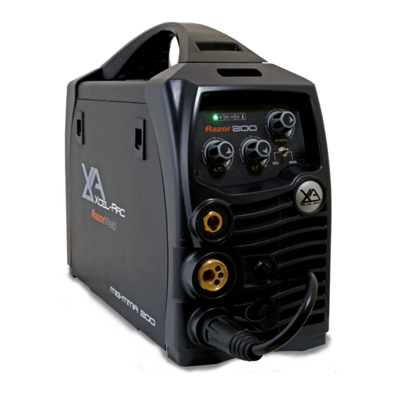
Overview The Razor-MIG200 from Xcel-Arc is a high quality inverter MIG welding machine with added MMA (stick electrode) function. At its heart is the very latest in IGBT inverter technology with a 40KHz inverter frequency providing simply outstanding arc characteristics and performance. -
Page 8: Machine Layout Pictogram
Razor Weld MACHINE LAYOUT FRONT PANEL LAYOUT 1. Mains Power LED 2. VRD LED 3. Thermal Overload LED 4. Wire Feed Adjustment Knob (MIG/MAG) 5. Voltage Adjustment Knob (MIG/MAG) 6. MIG/MMA Selector Switch 7. Amperage Adjustment Knob (MMA) 8. “-” Output terminal 9. -
Page 9: Installation & Operation For Mma (Stick) Welding
INSTALLATION SET UP FOR MMA Razor Weld (STICK) WELDING WITH XA-MIG200 RAZORWELD Installation set up for MMA (Stick) Welding with XA-MIG200 RAZORWELD MA (Stick) Welding with XA-MIG200 RAZORWEL (1) Turn the power source on and select the MMA function with the Tig/MMA/Mig selector switch. (2) Connection of Output Cables Two sockets are available on this welding machine. -
Page 10: Mma (Stick) Welding Information
MMA (Manual Metal Arc) Welding One of the most common types of arc welding is manual metal arc welding (MMA) or stick welding. An electric cur- rent is used to strike an arc between the base material and a consumable electrode rod or ‘stick’. The electrode rod is made of a material that is compatible with the base material being welded and is covered with a flux that gives off gaseous vapours that serve as a shielding gas and providing a layer of slag, both of which protect the weld area from atmospheric contamination. - Page 11 MMA (Stick) Welding Fundamentals Electrode Selection As a general rule, the selection of an electrode is straight forward,in that it is only a matter of selecting an electrode of similar composition to the parent metal. However, for some metals there is a choice of several electrodes, each of which has particular properties to suit specific classes of work.
-
Page 12: Installation & Operation For Mig Welding With Gas
Installation set up for MIG with Gas for XA-MIG200RZ (1) Select the MIG function with the Tig/MMA/Mig selector switch. (2) Select Standard using the Standard/Spool Gun selector switch. (3) Plug the welding torch into the Euro Mig torch connection socket on the front panel, and tighten it. When connecting the torch be sure to tighten the connection. - Page 13 Continued set up for MIG with Gas for XA-MIG200RZ (9) Align the wire into the groove of the drive roller and close down the top roller making sure the wire is in the groove of the bottom drive roller, lock the pressure arm into place. (10) Apply a medium amount of pressure to the drive roller.
-
Page 14: Wire Feed Drive Roller Selection
Wire Feed Roller Selection The importance of smooth consistent wire feeding during MIG welding cannot be emphasized enough. Simply put the smoother the wire feed then the better the welding will be. Feed rollers or drive rollers are used to feed the wire mechanically along the length of the welding gun. Feed rollers are designed to be used for certain types of welding wire and they have different types of grooves machined in them to accommodate the different types of wire. -
Page 15: Wire Installation Set Up Guide
Wire Installation and Set Up Guide Again the importance of smooth consistent wire feeding during MIG welding cannot be emphasized enough. The correct installation of the wire spool and the wire into the wire feed unit is critical to achieving an even and consistent wire feed. -
Page 16: Installation & Operation For Mig Welding With No Gas
Installation set up for MIG with Gasless wire for XA-MIG200RZ (1) Switch on the machine, select the MIG function with the Tig/MMA/Mig selector switch. (2) Select Standard using the Standard/Spool Gun selector switch. (3) Plug the welding torch into the Euro Mig torch connection socket on the front panel, and tighten it. When connecting the torch be sure to tighten the connection. - Page 17 Continued set up for MIG with Gasless wire for XA-MIG200RZ (8) Carefully feed the wire over the drive roller into the outlet guide tube, feed through about 150mm into the torch receptacle. Check that the correct drive roller is being used. (9) Align the wire into the groove of the drive roller and close down the top roller making sure the wire is in the groove of the bottom drive roller, lock the pressure arm into place.
-
Page 18: Installation Guide For Mig Torch Liner Installation
Mig Torch Liner Installation (1) Lay the torch out straight on the ground and remove the front end parts (2) Remove the liner retaining nut. (3) Carefully pull the liner out of the torch cable assembly (4) Select the correct new liner and carefully unravel avoiding putting any kinks in the liner, if you kink the liner it will make it no good and will require replacement. - Page 19 Mig Torch Liner Types Mig Torch Liner Types Mig Torch Liners The liner is both one of the simplest and most important components of a MIG gun. Its sole purpose is to guide the welding wire from the wire feeder, through the gun cable and up to the contact tip. Steel Liners Most MIG gun liners are made from coiled steel wire also known as piano wire, which provides the liner with good during operational use.
-
Page 20: Mig Torch And Wire Feeder Set Up Guide For Aluminium Mig Wire
Torch & Wire Feed Set Up for Aluminium Wire (1) Lay the torch out straight on the ground and remove the front end parts (2) Remove the liner retaining nut. (3) Carefully pull the liner out of the torch cable assembly (4) Select a PA or liner, carefully and slowly feed the liner in short forward movements down the cable assembly all the way through and out the torch neck end. - Page 21 Continued Torch & Wire Feed Set Up for Aluminium Wire (10) Loosen off the inlet guide tube retaining screw (11) Remove the inlet guide tube from the front end machine euro connector using long nose pliers. (12) Carefully feed the extended PA liner section into the inlet guide tube hole of the machine euro connector (13) Feed the extended PA liner all the way up and over the drive roller (14) Tighten the torch euro connection to the machine euro connector...
-
Page 22: Installation & Operation For Mig Welding With Spool Gun
Installation set up of the Spool Gun for XA-MIG200RZ (1) Switch on the machine, select the MIG function with the Tig/MMA/Mig selector switch. (2) Select Spool Gun using the Standard/Spool Gun selector switch. (3) Connect the Spool Gun to the Euro Mig torch connection socket on the front panel, and tighten it. Connect the Spool Gun control cable to the receptacle and tighten it. - Page 23 Continued set up of the Spool Gun for XA-MIG200CRZ Continued set up of the Spool Gun for XA-MIG200RZ Carefully feed the wire through the red guide tube into meet the drive roller. Push down the tension Carefully feed the wire through the red guide tube into meet the drive roller. Push down the tension arm adjustment lever to release the drive roll pressure allowing the wire to be guided through the drive arm adjustment lever to release the drive roll pressure allowing the wire to be guided through the drive rollers into the gun neck.
-
Page 24: Mig (Metal Inert Gas) Welding
MIG (Metal Inert Gas) Welding Definition of MIG Welding MIG (metal inert gas) welding also known as GMAW (gas metal arc welding) or MAG (metal active gas welding), is a semi-automatic or automatic arc welding process in which a continuous and consumable wire electrode and a shielding gas are fed through a weld- ing gun. - Page 25 MIG (Metal Inert Gas) Welding Short Circuit Transfer - Short circuit transfer is the most common used method whereby the wire electrode is fed continuously down the welding torch through to and exiting the contact tip. The wire touches the work piece and causes a short circuit the wire heats up and begins to form a molten bead, the bead separates from the end of the wire and forms a droplet that is transferred into the weld pool.
-
Page 26: Basic Mig Welding Guide
Basic MIG Welding Good weld quality and weld profile depends on gun angle, direction of travel, electrode extension (stick out), travel speed, thickness of base metal, wire feed speed (amperage) and arc voltage. To follow are some basic guides to assist with your setup. Gun Position - Travel Direction, Work Angle Gun position or technique usually refers to how the wire is directed at the base metal, the angle and travel direction chosen. - Page 27 Travel Angle - Travel angle is the right to left angle relative to the direction of welding. A travel angle of 5°- 15° is ideal and produces a good level of control over the weld pool. A travel angle greater that 20° will give an unstable arc condition with poor weld metal transfer, less penetration, high levels of spatter, poor gas shield and poor quality finished weld.
- Page 28 Travel Speed - Travel speed is the rate that the gun is moved along the weld joint and is usually measured in mm per minute. Travel speeds can vary depending on conditions and the welders skill and is limited to the welders ability to control the weld pool. Push technique allows faster travel speeds than Drag technique.
- Page 29 Wire types and sizes - Use the correct wire type for the base metal being welded. Use stainless steel wire for stainless steel, aluminium wires for aluminium and steel wires for steel. Use a smaller diameter wire for thin base metals. For thicker materials use a larger wire diameter and larger machine, check the recommended welding capability of you machine.
-
Page 30: Xa25 Mig Torch Parts Breakdown
MIG WELDING TORCHES XA25 MIG TORCH XA25 MIG TORCH XA25 MIG TORCH Suregrip Suregrip™ ™ Series Series 230A AIR COOLED MIG WELDING TORCH Rating:230A CO 200A mixed gas EN60974-7 @ 60% duty cycle. 0.8 to 1.2mm wires Front end parts shown on opposite page Liners shown on opposite page... - Page 31 MIG WELDING TORCHES XA25 MIG TORCH Suregrip Suregrip™ ™ Series Series XA25 MIG TORCH CONSUMABLES XA25 MIG TORCH CONSUMABLES Front end consumables XA25 Contact Tips Part Number Description XA2504-06 Contact Tip ECu 0.6mm D6 M6 x 28mm XA2504-08 Contact Tip ECu 0.8mm D8 M6 x 28mm XA2504-09 Contact Tip ECu 0.9mm D8 M6 x 28mm XA2504-10...
-
Page 32: Xasp24 Spool Gun Torch Parts Breakdown
MIG WELDING TORCHES XASP24 SPOOL GUN Suregrip Suregrip™ ™ Series Series 220A AIR COOLED SPOOL ON GUN MIG WELDING TORCH Rating:220A CO 200A mixed gas EN60974-7 @ 60% duty cycle. 0.8 to 1.2mm wires Wear parts next page Torch Model Part Number Description XASP24-24-P1-60ER... - Page 33 MIG WELDING TORCHES XASP24 SPOOL GUN Suregrip Suregrip™ ™ Series Series XASP24 MIG TORCH CONSUMABLES XASP24 MIG TORCH CONSUMABLES Front end consumables XA24 Contact Tips Part Number Description XA2504-06 Contact Tip ECu 0.6mm D6 M6 x 28mm XA2504-08 Contact Tip ECu 0.8mm D8 M6 x 28mm XA2504-09 Contact Tip ECu 0.9mm D8 M6 x 28mm XA2504-10...
-
Page 34: Mig Welding Trouble Shooting Guide
MIG WELDING TROUBLE SHOOTING The following chart addresses some of the common problems of MIG welding. In all cases of equipment malfunction, the manu- facturer’s recommendations should be strictly adhered to and followed. 1: Excessive Spatter Possible Reason Suggested Remedy Wire feed speed set too high Select lower wire feed speed Voltage too high... - Page 35 MIG WIRE FEED TROUBLE SHOOTING MIG WIRE FEED TROUBLE SHOOTING The following chart addresses some of the common WIRE FEED problems during MIG welding. In all cases of equipment malfunction, the manufacturer’s recommendations should be strictly adhered to and followed. 1: No wire feed Possible Reason Suggested Remedy...
-
Page 36: Mma Welding Trouble Shooting Guide
MMA (Stick) WELDING TROUBLE SHOOTING The following chart addresses some of the common problems of MMA welding. In all cases of equipment malfunction, the manufacturer’s recommendations should be strictly adhered to and followed. 1: No arc Possible Reason Suggested Remedy Incomplete welding circuit Check earth lead is connected. -
Page 37: Warranty Terms And Conditions
WARRANTY TERMS ESSETI New Zealand Limited (‘us’, ‘we’) warrants that the products bearing the brand names ESSETI, XCEL-ARC, RAZORWELD, RAZORCUT, JASIC, VIPER, T&R, XCEL-GAS, Otos, Servore, TECNA & HIT-8SS supplied by us and purchased by you from an Authorised ESSETI (NZ) Ltd. Distributor are free of Material and Faulty Workmanship Defects except for those products listed under ‘Warranty Exclusions’... - Page 38 WARRANTY TERMS WARRANTY / RETURNS / EXCHANGES Our Warranty Returns Policy recognises all and any rights you have under New Zealand Consumer Law and other relevant laws. You shall inspect the goods on delivery and shall within seven (7) days of delivery (time being of the essence) notify the Esseti NZ Ltd. Authorised Distributor from whom you purchased the goods of any alleged defect, shortage in quantity, damage or failure to comply with the description or quote.
- Page 39 Tungsten Electrodes, Collet, Collet Body, Alumina Nozzle, Torch Head, Torch Head water Cooled, Torch Head Flexible, Back Caps, Gas Lens, Torch Handle, Cup Gasket, Torch Body Gas Valve, O-ring, All XCEL-ARC TIG Welding Rods, All XCEL-ARC / Magmaweld Electrodes, Arc Leads, Welding Cable, Electrode Holder, Earth Clamps •...
- Page 40 Razor Weld New Zealand Limited Esseti New Zealand Limited PO Box 4189, Palmerston North - 4442 Phone: 06 355 1103 Fax: (06) 354 2437 Email: sales@esseti.co.nz www.esseti.co.nz Xcel-Arc © Esseti NZ LTD - 2020...
Need help?
Do you have a question about the RAZORWELD MIG200 and is the answer not in the manual?
Questions and answers