Table of Contents
Advertisement
Advertisement
Table of Contents

Related Manuals for DAYLIFF SUNFLO-X


Summary of Contents for DAYLIFF SUNFLO-X
- Page 1 SUNFLO-X DC SOLAR SUBMERSIBLE PUMP Installation & Operating Manual...
- Page 2 INDEX PUMP SPECIFICATIONS 2. SYMBOLS & WARNINGS 3. INSTALLATION & WIRING 3.1 Pump Installation 3.2 Pump Lowering 3.3 Pump Operation 3.4 Enclosure Socket Description 3.5 External Socket Description 3.6 Water Level Switch 3.7 Earthing Instructions 3.8 Panel Layout & Instructions 4.
- Page 3 SERVICE & MAINTENANCE 6.1 Routine Inspection & Maintenance 6.2 Requirement of Inspection & Maintenance TERMS OF WARRANTY...
-
Page 4: Pump Specifications
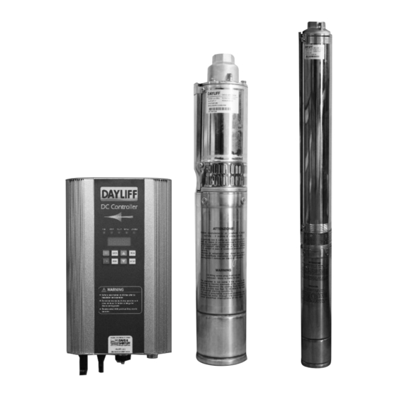
FLOW (m /hr) PUMP DAYLIFF SUNFLO-X Range of pumps are high specification solar powered centrifugal and helical rotor DC pumps specifically designed for borehole applications and feature a remote surface mounted controller. Pumps are constructed principally from AISI 304 stainless steel and are engineered to the highest standards to give serviceability, excellent efficiency, high reliability and long life. -
Page 5: Symbols And Warnings
Model Current Voltage (kg) Voltage Ø (VDC) SUNFLO-X 600H Helical Rotor 60-120VDC SUNFLO-X 1200H Helical Rotor 120-160VDC Centrifugal SUNFLO-X 1800C 120-160VDC 1040 Ø 2. SYMBOLS AND WARNINGS Misuse will result in fire, serious injury to person or even death. DANGER Misuse may damage equipment or cause light to medium injuries to a person. - Page 6 Earth terminal must be reliably grounded or else inverter enclosure may be electrified. WARNING The selection of solar array, motor and inverter should be compatible. In case of doubt, consult nearest Dayliff dealer. NOTE Terminals should be tightly fastened or else there is risk of arcing and fire.
-
Page 7: Installation And Wiring
The temperature of heat sink is normally high when inverter is running and it should not be touched or else it may cause burns. WARNING For areas with altitude over 2000m, the inverter output current should be derated at 10% for every 1500m increase in height. WARNING Maintenance and inspection must be performed by a qualified technician. - Page 8 When positioning the pump it is important to ensure adequate motor cooling Ÿ through water flow past the motor. This will be achieved by installing the pump suction above the borehole main aquifer or well screen and if not possible or in cases of open water installation a cooling sleeve must be used.
- Page 9 As the valve is being opened, the water output should be monitored to ensure that Ÿ the pump output does not exceed the borehole capacity as indicated by the pump starting and stopping on the low level relay (if fitted) or uneven water flow at the outlet.
-
Page 10: Water Level Switch
3.5 External Socket Description Left Side Wire Description Connection Description Socket Connection Connected to positive side of One-strand, black solar array Connected to negative side of One-strand, black solar array Connected to protective ground Yellow wire (yellow green) (1) green wire Connected to U phase of the Red wire motor (black) (2) -
Page 11: Earthing Instructions
(P ,N) (PE) (U, V, W) Model (mm ) (mm ) (mm ) (mm ) ≤ SunFlo-X 600H ≤ SunFlo-X 1200H ≤ SunFlo-X 1800C Ambient temperature condition for the above-recommended wire size is ≤60°C. NOTE 3.7 Earthing Instructions The inverter must always be earthed with an earthing conductor connected to earthing terminal. - Page 12 10°. WARNING 3.8 Panel Layout and Instruction Dayliff solar pumping inverter uses LED display operation panel as shown in the figure below, it includes 5 LED lights and 5-digit 8-SEG nixie tubes and 8 keys in 2 rows. Fig. 6...
-
Page 13: Operation
Indicator Lights & Name Function Description Keys 1. Decrease parameter number or its value in control parameter display status Decreasing Key 2. Decrease output frequency or display current running data according to operation mode Enter or quit from the display status of the control Programming Key PROG parameter... -
Page 14: Display Status
Step Debugging Content Instruction Modify the control parameter as read-write Press “STOP” to stop the operation when power on. Modify Pr.0 value to 0. parameter Refer to page 8 for recommended sensor type 1. Modify Pr.31value to 1 if using Normally-Close type water level switch Modify the setting of for well. - Page 15 4.3 View Current Operational Parameters Description Operation Display Initial Status: Current running data Display current running F. 5000 Example: data. MODE Indicate: 50.00Hz Output frequency of the inverter Ud. 120 Display current running data Example: MODE Input voltage of the inverter Indicate: 120V Display current running data Example:...
- Page 16 4.4 View or Modify the Control Parameters Description Display Operation Enter the parameter modification Initial Status: non-control Pr. 0 interface parameter display Indicate Pr.0 Display parameter 0 PROG Select the parameter to be viewed pr.031 Example: and modified Indicate: Pr.31 Display parameter number Confirm to view and modify the Example:...
-
Page 17: Function Parameter Description
The modification can be only applied when Pr.33 value is 0. NOTE 4.6 Function Parameter Description Factory Scope Description Name Number Value 0: Parameter can be read and edited. Other parameter values cannot be modified until Mode of parameter Pr.0 is modified to 0. Pr.0 setting 1: All parameters can only be read. -
Page 18: Troubleshooting
5. TROUBLE SHOOTING 5.1 Fault Codes Description and Counter Measure DC solar pumping inverters have complete protection functions. When system fault occurs, the inverter will take protection counter measures: The general protection measure is to stop the inverter immediately and not allow the inverter to restart in a while. When fault or protection occurs, the inverter operation panel will automatically display the blinking fault code in the last 2 digit nixie tubes. - Page 19 5.2 Other Codes Description Relevant Description Code Code Description p 1.u. Return to normal after resetting Parameter initialisation Important parameter p e.c Return to normal after resetting modification l-600 48V rated voltage Inverter model :110V rated voltage h-1800 600:1800 :rated power on 30 Start delay time Countdown of the restart: 30 seconds...
- Page 20 PROBLEM POSSIBLE CAUSE SOLUTION Indicator light is off Check DC input wires connection Inverter does not work when Cut of inverter input wires and check Indicator light is on powered on if input voltage is abnormal Reset the motor starter overload. If it The motor overload has tripped out trips again, check the voltage and if normal call service technician...
- Page 21 PROBLEM POSSIBLE CAUSE SOLUTION The water level sensor not installed Check water level sensor and correct correctly Pull out the pump and clean or Frequent starts The non-return valve is leaking or stuck replace the non-return valve and stops half open Increase the installation depth of the pump, throttle the pump or replace it The pump is oversized for borehole...
- Page 22 6. SERVICE AND MAINTENANCE 6.1 Routine Inspection and Maintenance The inverter is affected by ambient temperature, humidity, dust, vibration and internal device aging of the inverter. To make the inverter operate for longer, periodic inspect must be carried out every year. 6.2 Requirement of Inspection and Maintenance The inspection must be performed by a qualified technical personnel and the power •...
-
Page 23: Terms Of Warranty
7. TERMS OF WARRANTY i) General Liability • In lieu of any warranty, condition or liability implied by law, the liability of Dayliff Ÿ (hereafter called the Distributor) in respect of any defect or failure of equipment supplied is limited to making good by replacement or repair (at the Distributor’s discretion) defects which under proper use appear therein and arise solely from faulty design, materials or workmanship within a specified period. - Page 24 www.davisandshirtliff.com INS386B-07/20...
Need help?
Do you have a question about the SUNFLO-X and is the answer not in the manual?
Questions and answers