Table of Contents
Advertisement
Advertisement
Table of Contents

Related Manuals for DAYLIFF AQUASTRONG SMART 45


Summary of Contents for DAYLIFF AQUASTRONG SMART 45
- Page 1 AQUASTRONG SMART 45 Water Boosting Pump Installation & Operating Manual...
-
Page 2: Table Of Contents
INDEX SPECIFICATIONS 2. WARNINGS AND SYMBOLS 3. INSTALLATION 3.1 Location 3.2 Minimum Space 3.3 System Sizing 3.4 Piping Connection 3.5 Mains Water Pressure Boosting 3.6 Suction from a Well 3.7 Suction from fresh Water Tank 4. OPERATION 4.1 Priming the Pump 4.2 Starting the Pump 4.3 Setting the Correct Pressure 4.4 Control Panel... -
Page 3: Specifications
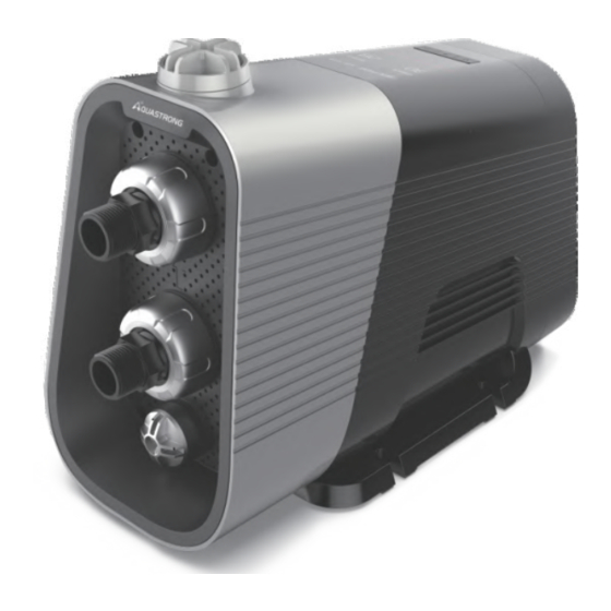
Congratulations on selecting Dayliff Aquastrong Smart 45 Water Boosting System. They are manufactured to the highest standards and if installed and operated correctly will give many years of efcient and trouble free service. Careful reading of this Installation Manual is therefore important, though should there be any queries they should be referred to the equipment supplier. - Page 4 PUMP Dayliff Aquastrong SMART45 is a highly innovative smart variable speed water boosting pump ideal for automatic pressurised water supply for houses, apartments, offices and other small-scale applications where reliable water supply is demanded, the variable speed technology providing constant pressure at varying water demand.
-
Page 5: Warnings And Symbols
Installation Arrangement Weight:17kg 2. WARNINGS AND SYMBOLS Electrical work to be carried out by competent qualied and licensed electrician. WARNING Any action that doesn’t comply with safety warning sign may cause personal injury, pump damage and losses in property. Users must also comply with the local safety regulations. WARNING Ensure no water leakage onto the pump motor or its electrical connections during installations, venting or... -
Page 6: Installation
3. INSTALLATION 1. Pressure Tank 2. Flow Sensor 3. Pressure Sensor 4. Rear Bearing 5. Front Bearing 6. Mechanical Seals 3.1 Location The pump can be installed indoors or outdoors but it must not be exposed to inclement weather. It is recommended that the pump is installed near a drain or in a drip tray connected to a drain in order to lead away possible condensation from cold surfaces. -
Page 7: Piping Connection
3.4 Piping Connection Ensure that the pump is not stressed by the piping system. Flexible hose is strongly recommended. WARNING Always loosen and tighten the union nuts on the inlet and outlet port by hand. Damage to the inlet and outlet ports increases the risk of leakage. -
Page 8: Mains Water Pressure Boosting
3.5 Mains Water Pressure Boosting 1. Highest tap 2. Ball Valve 3. Inlet Filter 4. Foot Valve with Strainer 5. Drip Tray 3.7 Suction from Water Tank 3.6 Suction from a Well Install the pump on a small stand to prevent the ventilation holes from being ooded. -
Page 9: Operation
4. OPERATION 4.1 Priming the pump Unscrew the priming plug and pour atleast 1.2 litres of water into the pump. 4.2 Starting the pump 1. Open a tap to prepare the pump for venting. 2. Plug pump onto power and the pump will start shortly. 3. -
Page 10: Control Panel
Maximum Set Point Well application Tank below ground level Tank above ground level Boosting from well or tank 3Bar 4Bar Boosting from mains 5.5Bar 5Bar The pressure settings of 4.5, 5.0 and 5.5bar require a positive 4.5Bar inlet pressure and the settings WARNING must only be used when boosting from the water mains. - Page 11 Full Automatic Mode: In automatic mode, set pressure and operating pressures are shown on the display. Adjust the pump’s pressure by pressing the “+” or “-” button. Setting ranges from 1.5 to 5.5bar. Forced Start Mode: In forced mode, motor speed is shown on the display. Adjust the motor rotations’...
-
Page 12: Trouble Shooting
4. Dry running fault Check the water supply and prime the pump. 5. Overheating protection Switch off the pump, wait for the motor to cool down and restart. If the indicator does not go off, contact authorized D&S dealer. switch 6. -
Page 13: Maintenance And Storage
PROBLEM POSSIBLE CAUSE SOLUTION Delivery height too big Readjust to allowable delivery height Use pressure line with larger Pressure line diameter too small diameter Flow rate Suction opening is blocked Clean suction opening insufficient Pressure line is kinked Straighten pressure line Seal pressure line and tighten Pressure line leaks threaded connections... -
Page 14: Terms Of Warranty
7. TERMS OF WARRANTY i) General Liability • In lieu of any warranty, condition or liability implied by law, the liability of Dayliff (hereafter called the Distributor) in respect of any defect or failure of equipment supplied is limited to making good by replacement or repair (at the Distributor’s discretion) defects which under proper use appear therein... - Page 16 INS481A-03/21...
Need help?
Do you have a question about the AQUASTRONG SMART 45 and is the answer not in the manual?
Questions and answers
Здравствуйте. Нужен ли гидроаккумулятор для данного насоса?
The provided context does not mention the need for a pressure tank for the DAYLIFF AQUASTRONG SMART 45 pump. It is described as a "smart water boosting system" with "plug and play" installation, suggesting it operates without requiring additional components like a pressure tank.
This answer is automatically generated