Table of Contents
Advertisement
Quick Links
Advertisement
Table of Contents

Related Manuals for DAYLIFF DS


Summary of Contents for DAYLIFF DS
- Page 1 DS/DSP/D3SP Submersible Borehole Pumps Installation & Operating Manual...
-
Page 2: Table Of Contents
INDEX PUMP SPECIFICATIONS Pump Motor 2. DELIVERY & STORAGE Delivery Storage & Handling PUMP ACCESSORIES Drop Cable Riser Pipe iii) Well Head ELECTRICAL CONNECTIONS General Information Single Phase Motors iii) Three Phase Motors INSTALLATION Pump Application Pump Position iii) Pump Lowering PUMP OPERATION MAINTENANCE TROUBLE SHOOTING... -
Page 3: Pump Specifications
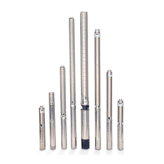
Pump DAYLIFF DS and DSP submersible multistage centrifugal pumps are specially designed for water supply from boreholes. DS pumps feature stainless steel construction throughout while DSP pumps use engineering plastics for the hydraulic components and feature a floating type impeller that gives superior sand handling capabilities. -
Page 4: Ii) Motor
2. DELIVERY & STORAGE Delivery DAYLIFF DS/DSP/D3SP pumps are supplied from the factory in proper packing in which they should remain until they are to be installed. During unpacking and prior to installation, care must be taken when handling the pump to ensure that misalignment does not occur due to bending. -
Page 5: Ii) Riser Pipe
This will then require expensive pump removal or possibly borehole loss. The following should be noted:- Either MS galvanised steel pipe in 6m or 3m sections or DAYLIFF PVC borehole Ÿ piping in 3m section should be used for all installations below 50m. For shallow well installations up to 50m single length Polypipe can be used. -
Page 6: Electrical Connections
The rated maximum current, supply voltage and cosØ are given on a loose data Ÿ plate supplied with the pumps which must be fitted close to the installation site. The required voltage quality for DAYLIFF DS motors measured at the motor Ÿ terminals is -10%/+10% of the nominal rated voltage during continuous operation including variations in the supply voltage and cable losses. -
Page 7: Ii) Single Phase Motors
Dayliff AVS. For motors larger than 1.1kW a DOL starter is required and this can be provided by a separate DOL contactor and overload unit or... -
Page 8: Installation
Minimum Borehole Diameter 3”pumps -100mm, 4”pumps-110mm, 6”pumps- Ÿ 160mm, DS30-200mm. Maximum Pump Immersion Depth - 200m for DSP , 250m for DS and 35m for Ÿ D3SP . Pumped liquid should be clean, thin and non-explosive containing no solid 3 Ÿ... -
Page 9: Ii) Pump Position
ii) Pump Position Borehole Measurement Parameters L1.Minimum installation depth below dynamic water level L2. Depth to dynamic water level (DWL) L3.Depth to static water level (SWL) L4.Draw down. This is the difference between the dynamic and the static water levels L5. -
Page 10: Pump Operation
Fit the first starter pipe into the pump outlet and ensure a tight leak free joint Ÿ while the pump is on the surface. The thread on the starter pipe should not be longer than the threads in the pump outlet or it will interfere with operation of the non-return valve. -
Page 11: Maintenance
In order to obtain maximum pump life the number of starts should be controlled Ÿ and should not exceed 30 per hour. It is also necessary to start the pump at least monthly to prevent seizure. 7. MAINTENANCE No regular maintenance is required though periodically, recommended every 3 Ÿ... -
Page 12: Trouble Shooting
8. TROUBLE SHOOTING GUIDE Problem Possible Cause Solution Replace the blown fuses. If the replacements blow too, The fuses are blown the electric installation and the submersible drop cable should be checked The ELCB or the voltage- operated ELCB has tripped Re-set the circuit breaker Contact the power supply No electricity supply... - Page 13 The discharged valve is Open the valve closed Increase the installation depth of the pump, throttle No water or very low level in the pump or replace it with borehole a smaller model to obtain reduced capacity The pump runs but The non-return valve is stuck Pull out the pump and clean gives no...
- Page 14 Adjust the intervals of the electrodes to ensure suitable time between the cutting-in and cutting-out of the pump. The water level electrodes If the intervals between or level switches have not stop/start cannot be changed been installed correctly automatically, the pump capacity may be reduced by throttling the discharge valve Frequent...
-
Page 15: Warranty
9. TERMS OF WARRANTY i) General Liability • In lieu of any warranty, condition or liability implied by law, the liability of Davis & Shirtliff (hereafter called the Company) in respect of any defect or failure of equipment supplied is limited to making good by replacement or repair (at the Company's discretion) defects which under proper use appear therein and arise solely from faulty design, materials or workmanship within a specified period. - Page 16 INS 278C - 08/18...
Need help?
Do you have a question about the DS and is the answer not in the manual?
Questions and answers