Vega VEGAFLEX 65 Operating Instructions Manual
Foundation fieldbus
Hide thumbs
Also See for VEGAFLEX 65:
- Operating instructions manual (57 pages) ,
- Operating instructions manual (47 pages) ,
- Operating instructions manual (64 pages)
Table of Contents
Advertisement
Quick Links
Advertisement
Table of Contents

Related Manuals for Vega VEGAFLEX 65


Summary of Contents for Vega VEGAFLEX 65
- Page 1 Operating Instructions VEGAFLEX 65 Foundation Fieldbus Guided Microwave...
-
Page 2: Table Of Contents
Setup procedure ..... . . 24 Menu schematic ..... . . 29 VEGAFLEX 65 • Foundation Fieldbus... - Page 3 "Product description". Instructions manuals for accessories and replacement parts Tip: To ensure reliable setup and operation of your VEGAFLEX 65, we offer accessories and replacement parts. The associated documents are: 27720 - VEGADIS 61 30207 - Electronics module VEGAFLEX series 60...
-
Page 4: About This Document
This symbol indicates special instructions for Ex applications. List The dot set in front indicates a list with no implied sequence. à Action This arrow indicates a single action. Sequence Numbers set in front indicate successive steps in a procedure. VEGAFLEX 65 • Foundation Fieldbus... -
Page 5: For Your Safety
During work on and with the device the required personal protection equipment must always be worn. 2.2 Appropriate use VEGAFLEX 65 is a sensor for continuous level measurement. You can find detailed information on the application range in chapter "Product description". -
Page 6: Safety Approval Markings And Safety Tips
NE 53 is fulfilled. This applies also to the corresponding indicating and adjustment components. VEGA instruments are generally upward and downward compatible. Sensor software for DTM VEGAFLEX 65 HART, PA or FF DTM VEGAFLEX 65 for adjustment software PACTware Indicating and adjustment module for sensor software The parameter adjustment of the basic sensor functions is independent of the software version. -
Page 7: Safety Instructions For Ex Areas
PACTware on the type label of the electronics via the indicating and adjustment module You can view all software histories on our website www.vega. com. Make use of this advantage and get registered for update information via e-mail. 2.8 Safety instructions for Ex areas Please note the Ex-specific safety information for installation... -
Page 8: Product Description
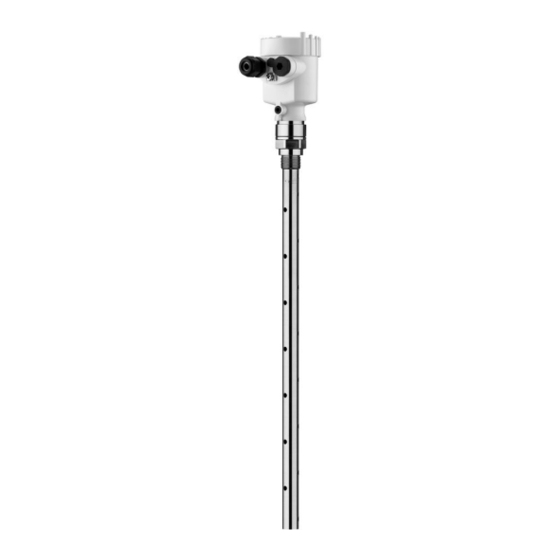
Process fitting with probe Housing with electronics Housing cover, optionally available with indicating and adjustment module Fig. 1: VEGAFLEX 65 with single chamber housing Housing cover with integrated indicating and adjustment module (optional) Housing with electronics Process fitting The type label contains the most important data for identi- Type label fication and use of the instrument:... -
Page 9: Principle Of Operation
In addition to the type label outside, you can also find the serial number on the inside of the instrument. 3.2 Principle of operation VEGAFLEX 65 is a level sensor with pipe probe for continuous Application range level measurement. -
Page 10: Packaging, Transport And Storage
3 Product description with indicating and adjustment module with the suitable VEGA DTM in conjunction with an adjustment software according to the FDT/DTM standard, e.g. PACTware and PC a configuration tool The entered parameters are generally saved in VEGAFLEX 65, optionally also in the indicating and adjustment module or in PACTware. -
Page 11: Mounting
Fig. 2: Measures against moisture penetration The reference plane for the measuring range of the sensors is Measuring range the seal surface of the thread. VEGAFLEX 65 • Foundation Fieldbus... -
Page 12: Mounting Instructions
The max. permissible pressure is specified in chapter "Technical data" or on the type label of the sensor. 4.2 Mounting instructions Mount VEGAFLEX 65 in such a way that the probe does not Mounting position touch any installations or the vessel wall during installation. - Page 13 Excessive system vibration or shocks, e.g. caused by agitators or turbulence in the vessel (e.g. from fluidisation) can cause the coax probe of VEGAFLEX 65 to vibrate in resonance. Should a coax probe of more than 1 m (3.281 in) length should be used, you can provide a suitable support or guy directly above the end of the probe to stabilise it.
-
Page 14: Connecting To Power Supply
If overvoltage surges are expected, overvoltage arresters should be installed according to Foundation Fieldbus specification Tip: We recommend VEGA overvoltage arrester B63-32. In hazardous areas you should take note of the appropriate Take note of safety instruc- regulations, conformity and type approval certificates of the tions for Ex ap- sensors and power supply units. -
Page 15: Connection Steps - Instrument Housing
1 cm (0.4 in) insulation from the ends of the individual wires 5 Insert the cable through the cable gland into the sensor 6 Lift the opening levers of the terminals with a screwdriver (see following illustration) VEGAFLEX 65 • Foundation Fieldbus... -
Page 16: Wiring Plan, Single Chamber Housing
12 Screw the housing cover on The electrical connection is finished. 5.3 Wiring plan, single chamber housing The following illustrations apply to the non-Ex as well as to the Ex-ia version. VEGAFLEX 65 • Foundation Fieldbus... - Page 17 Plug connector for VEGACONNECT (I²C interface) Spring-loaded terminals for connection of the external indication VEGADIS Ground terminal for connection of the cable screen Spring-loaded terminals for Foundation Fieldbus connection Simulation switch ("on" = mode for simulation release) VEGAFLEX 65 • Foundation Fieldbus...
-
Page 18: Wiring Plan, Double Chamber Housing
Ex-ia version. Housing overview Fig. 9: Double chamber housing Housing cover, connection compartment Blind stopper or plug M12 x 1 for VEGADIS 61 (optional) Housing cover, electronics compartment Filter element for air pressure compensation Cable gland VEGAFLEX 65 • Foundation Fieldbus... - Page 19 Internal connection cable to the connection compartment Connection compart- ment I ² C Fig. 11: Connection compartment, double chamber housing Plug connector for VEGACONNECT (I²C interface) Ground terminal for connection of the cable screen Spring-loaded terminals for voltage supply VEGAFLEX 65 • Foundation Fieldbus...
-
Page 20: Wiring Plan - Version Ip 66/Ip 68, 1 Bar
5.5 Wiring plan - version IP 66/IP 68, 1 bar Wire assignment, con- nection cable Fig. 13: Wire assignment, connection cable brown (+) and blue (-) to power supply or to the processing system Shielding VEGAFLEX 65 • Foundation Fieldbus... -
Page 21: Set Up With The Indicating And Adjustment Module
4 Screw housing cover with inspection window tightly back Removal is carried out in reverse order. The indicating and adjustment module is powered by the sensor, an additional connection is not necessary. VEGAFLEX 65 • Foundation Fieldbus... - Page 22 Fig. 14: Installation of the indicating and adjustment module Note: If you intend to retrofit the instrument with an indicating and adjustment module for continuous measured value indication, a higher cover with an inspection glass is required. VEGAFLEX 65 • Foundation Fieldbus...
-
Page 23: Adjustment System
The functions of the individual keys are shown in the above illustration. Approx. 10 minutes after the last pressing of a key, an automatic reset to measured value indication is triggered. Any values not confirmed with [OK] will not be saved. VEGAFLEX 65 • Foundation Fieldbus... -
Page 24: Setup Procedure
6 Set up with the indicating and adjustment module PLICSCOM 6.4 Setup procedure After VEGAFLEX 65 is connected to voltage supply or after Switch on phase voltage recurrence, the instrument carries out a self-check for approx. 30 seconds. The following steps are carried out: Internal check of the electronics Indication of the instrument type, the firmware as well as... - Page 25 The cursor jumps now to the distance value. 2 Enter the appropriate distance value in m (corresponding to the percentage value) for the full vessel. Keep in mind that the max. level must lie below the dead band. VEGAFLEX 65 • Foundation Fieldbus...
- Page 26 A linearization is necessary for all vessels in which the vessel Linearisation curve volume does not increase linearly with the level - e. g. with a cylindrical or spherical tank - and the indication or output of the VEGAFLEX 65 • Foundation Fieldbus...
- Page 27 Linearisation curve Sensor-TAG Displayed value Unit of measurement Language Sensitivity The following safety-relevant data are not read out or written: HART mode Sensor length/Sensor type Gating out of false signals Copy sensor data Copy sensor data? VEGAFLEX 65 • Foundation Fieldbus...
- Page 28 You will find a detailed description of these menu items in the operating instructions manual "Indicating and adjustment module". Sensor-specific basic adjustment. Special parameters are parameters which are set customer-specifically on the service level with the adjustment software PACTware. VEGAFLEX 65 • Foundation Fieldbus...
-
Page 29: Menu Schematic
Display ▶ Diagnostics Service Info Pointer Sensor status Curve selection Echo curve Distance min.: 0.580 m(d) Echo curve Presentation of the echo Dist. max.: 16.785 m(d) curve Service Basic adjustment Display Diagnostics ▶ Service Info VEGAFLEX 65 • Foundation Fieldbus... - Page 30 Last change using PC < max. 32 characters > VEGAFLEX 6x 12. Dec. 2005 19. August 2003 Sensor-TAG (PD_TAG) Serial number Software version < max. 32 characters > 12345678 3.22 17:48 h Sensor characteristics Version: VEGAFLEX 65 • Foundation Fieldbus...
-
Page 31: Setup With Pactware And Other Adjustment Programs
A detailed description is available in the online help of PACTware and the VEGA DTMs. Note: Keep in mind that for setup of VEGAFLEX 65, DTM-Collection in the actual version must be used. VEGAFLEX 65 • Foundation Fieldbus... -
Page 32: Parameter Adjustment With Ams
All currently available VEGA DTMs are provided in the DTM Collection on CD and can be obtained from the responsible VEGA agency for a token fee. This CD includes also the up-to- date PACTware version. The basic version of this DTM Collection incl. -
Page 33: Maintenance And Fault Rectification
24 hour service hotline However, should these measures not be successful, call the VEGA service hotline in urgent cases under the phone no. +49 1805 858550. The hotline is available to you 7 days a week round-the-clock. - Page 34 à Carry out a software update or send the instrument for repair ? E042/E043 Hardware error, electronics defective à Exchange instrument or return instrument for repair ? E113 Communication conflict à Exchange instrument or return instrument for repair VEGAFLEX 65 • Foundation Fieldbus...
-
Page 35: Exchanging The Electronics Module
Internet (see operating instructions manual "Oscillator"). In both cases, the serial number of VEGAFLEX 65 is required. The serial numbers are stated on the type label of VEGAFLEX 65, on the inner wall of the housing or on the delivery note. - Page 36 Attach the completed form and probably the safety data sheet outside on the packaging Please ask the agency serving you for the address of your return shipment. You can find the respective agency on our website www.vega.com under: "Company - VEGA world- wide" VEGAFLEX 65 • Foundation Fieldbus...
-
Page 37: Dismounting
Correct disposal avoids negative effects to persons and environment and ensures recycling of useful raw materials. Materials: see chapter "Technical data" If you have no possibility to dispose of the old instrument professionally, please contact us concerning return and disposal. VEGAFLEX 65 • Foundation Fieldbus... -
Page 38: Supplement
920 g/m (9.9 oz/ft) Sensor length L (from seal surface) - Tube: ø 21.3 mm (0.839 in) 0.5 … 6 m (1.64 … 19.69 ft) < 1 mm (0.039 in) Trimming accuracy - tube VEGAFLEX 65 • Foundation Fieldbus... - Page 39 Min. dielectric figure of the medium ε Dead band - coax version 30 mm (1.181 in) - top 0 mm - bottom Fig. 17: Measuring ranges of VEGAFLEX 65 Reference plane Probe length Measuring range Upper dead band Output variable Output...
- Page 40 ") -10 mm ") 0,03 m (0.1 ft) (20 ft) Fig. 18: Accuracy VEGAFLEX 65 - coax version Ambient conditions Ambient, storage and transport tem- -40 … +80 °C (-40 … +176 °F) perature Incl. non-linearity, hysteresis and non-repeatability. VEGAFLEX 65 • Foundation Fieldbus...
- Page 41 -40 °C 0 °C 50 °C 100 °C 150 °C (-40 °F) (32 °F) (122 °F) (212 °F) (302 °F) Fig. 19: Ambient temperature - Process temperature Ambient temperature Process temperature (depending on the seal material) VEGAFLEX 65 • Foundation Fieldbus...
- Page 42 1 x IP 68 cable gland M20 x 1.5; 1 x blind - Double chamber housing stopper M20 x 1.5; 1 x blind stopper M16 x 1.5 Depending on the version M12 x 1, according to DIN 43650, Harting, Am- phenol-Tuchel, 7/8" FF. VEGAFLEX 65 • Foundation Fieldbus...
- Page 43 Supply voltage with lighted indicating and adjustment module 12 … 32 V DC - Non-Ex instrument 12 … 24 V DC - EEx-ia instrument Power supply by/max. number of sensors max. 32 (max. 10 with Ex) - H1 power supply VEGAFLEX 65 • Foundation Fieldbus...
- Page 44 CI.I-III, Div 1 (IS); CSA CI.I-III, Div 1 (IS)+Cl.I- III, Div 1 Gr.C-G(XP) - Miscellaneous A suitable cable is the prerequisite for maintaining the protection class. Deviating data in Ex applications: see separate safety instructions. VEGAFLEX 65 • Foundation Fieldbus...
-
Page 45: Foundation Fieldbus
AI 2 Channel = 3: Secondary Value 2 (Distance Interface) Channel = 5: Total Sensor Value (Distance Level) Fig. 20: VEGAFLEX 65 measured value processing Diagram, adjustment The following illustration shows the function of the adjustment. VEGAFLEX 65 • Foundation Fieldbus... - Page 46 Highest Point cal_level_lo [%] Calibration Lowest Point Fig. 21: Adjustment VEGAFLEX 65 Parameter list The following list contains the most important parameters and their meaning: primary_value - This is the process value after adjustment and Linearization with the status of the...
- Page 47 - Min./Max. adjustment: this is the value of level at "Calibration Highest Point". The unit is defined in "level_unit When writing "cal_level_hi" and "cal_type" = 1, the "Calibration Highest Point" is automatically set to "sensor_value" VEGAFLEX 65 • Foundation Fieldbus...
- Page 48 - The actual distance from sensor to the product surface must be entered before creating a false echo memory The unit is defined in "sensor_range.Units Index" empty_vessel_curve_corr_op_code Create a false echo memory. Selectable codes are: update, create new and delete total_sensor_value VEGAFLEX 65 • Foundation Fieldbus...
-
Page 49: Dimensions
Fig. 22: Housing versions in protection IP 66/IP 67 and IP 66/IP 68, 0.2 bar (with integrated indicating and adjustment module the housing is 9 mm/0.35 in higher) Plastic housing Stainless steel housing, electropolished Stainless steel housing - precision casting Aluminium double chamber housing Aluminium housing VEGAFLEX 65 • Foundation Fieldbus... - Page 50 Fig. 23: Housing versions in protection IP 66/IP 68, 1 bar (with integrated indicating and adjustment module the housing is 9 mm/0.35 in higher) Stainless steel housing - precision casting Aluminium double chamber housing Stainless steel housing, electropolished Aluminium housing VEGAFLEX 65 • Foundation Fieldbus...
- Page 51 36 (G¾, ¾ NPT) 41 (G1, 1 NPT) 46 (G1½, 1½ NPT) G¾, ¾ NPT, G1, 1 NPT, G1½, 1½ NPT ø 21,3mm ") Fig. 24: VEGAFLEX 65 - threaded version Sensor length, see chapter "Technical data" VEGAFLEX 65 • Foundation Fieldbus...
- Page 52 3" 150 lb ø 7 " " ø 6" 4xø " 3" 150 lb ø 8 " " ø 6 " 4xø " Fig. 25: VEGAFLEX 65 - flange version Sensor length, see chapter "Technical data" VEGAFLEX 65 • Foundation Fieldbus...
-
Page 53: Industrial Property Rights
10 Supplement 10.4 Industrial property rights VEGA product lines are global protected by industrial property rights. Further information see http://www.vega.com. Only in U.S.A.: Further information see patent label at the sensor housing. VEGA Produktfamilien sind weltweit geschützt durch gewerbliche Schutzrechte. - Page 54 10 Supplement VEGAFLEX 65 • Foundation Fieldbus...
- Page 55 10 Supplement VEGAFLEX 65 • Foundation Fieldbus...
- Page 56 All statements concerning scope of delivery, application, practical use and operating conditions of the sensors and processing systems correspond to the information avail- able at the time of printing. © VEGA Grieshaber KG, Schiltach/Germany 2008 31848-EN-080716 Subject to change without prior notice...
Need help?
Do you have a question about the VEGAFLEX 65 and is the answer not in the manual?
Questions and answers