Vega VEGAFLEX 62 Operating Instructions Manual
Hide thumbs
Also See for VEGAFLEX 62:
- Product information (15 pages) ,
- Operating instructions manual (64 pages) ,
- Operating instructions manual (64 pages)
Table of Contents
Advertisement
Quick Links
Advertisement
Table of Contents

Related Manuals for Vega VEGAFLEX 62


Summary of Contents for Vega VEGAFLEX 62
-
Page 1: Operating Instructions
Operating Instructions VEGAFLEX 62 4 … 20 mA/HART - four-wire Guided Microwave... -
Page 2: Table Of Contents
Connecting the PC ..... 36 Parameter adjustment with PACTware ..37 Parameter adjustment with AMS™ and PDM . . 38 VEGAFLEX 62 • 4 … 20 mA/HART - four-wire... - Page 3 "Product description". Instructions manuals for accessories and replacement parts Tip: To ensure reliable setup and operation of your VEGAFLEX 62, we offer accessories and replacement parts. The associated documents are: 27720 - VEGADIS 61 30207 - Electronics module VEGAFLEX series 60...
-
Page 4: About This Document
The dot set in front indicates a list with no implied sequence. à Action This arrow indicates a single action. Sequence Numbers set in front indicate successive steps in a procedure. VEGAFLEX 62 • 4 … 20 mA/HART - four-wire... -
Page 5: For Your Safety
During work on and with the device the required personal protection equipment must always be worn. 2.2 Appropriate use VEGAFLEX 62 is a sensor for continuous level measurement. You can find detailed information on the application range in chapter "Product description". -
Page 6: Safety Approval Markings And Safety Tips
NE 53 is fulfilled. This applies also to the corresponding indicating and adjustment components. VEGA instruments are generally upward and downward compatible. Sensor software for DTM VEGAFLEX 62 HART, PA or FF DTM VEGAFLEX 62 for adjustment software PACTware Indicating and adjustment module for sensor software... -
Page 7: Safety Instructions For Ex Areas
The range of available functions depends on the respective software version of the individual components. The software version of VEGAFLEX 62 can be determined as follows: via PACTware on the type label of the electronics via the indicating and adjustment module You can view all software histories on our website www.vega. -
Page 8: Product Description
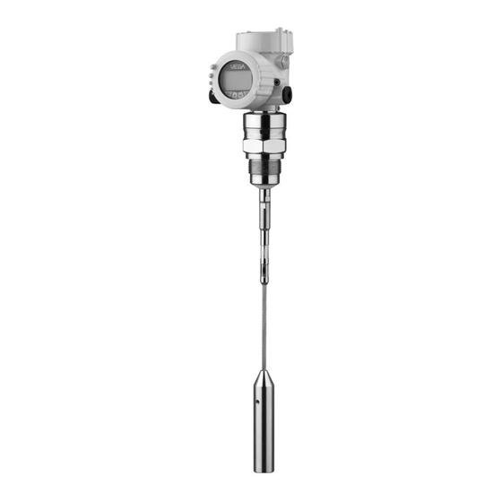
Process fitting with probe Housing with electronics Housing cover, optionally available with indicating and adjustment module Fig. 1: VEGAFLEX 62 - cable version with plastic housing Housing cover with integrated indicating and adjustment module (optional) Housing with electronics Process fitting... -
Page 9: Principle Of Operation
In addition to the type label outside, you can also find the serial number on the inside of the instrument. 3.2 Principle of operation VEGAFLEX 62 is a level sensor with cable or rod probe for Area of application continuous level measurement. -
Page 10: Packaging, Transport And Storage
Protected against solar radiation Avoiding mechanical shock and vibration Storage and transport temperature see "Supplement - Storage and transport temperature Technical data - Ambient conditions" Relative humidity 20 … 85 % VEGAFLEX 62 • 4 … 20 mA/HART - four-wire... -
Page 11: Mounting
Rod length 100 … 2000 mm (3.937 … 78.74 in) Thread length 18 mm (0.709 in) Make sure that the rod of the probe is at least 300 mm (11.811 in) away from the vessel wall VEGAFLEX 62 • 4 … 20 mA/HART - four-wire... - Page 12 This applies mainly to outdoor mounting as well as installation in areas where high humidity is expected (e. g. through cleaning processes) or on cooled or heated vessels. VEGAFLEX 62 • 4 … 20 mA/HART - four-wire...
-
Page 13: Mounting Instructions
"Technical data" or on the type label of the sensor. 4.2 Mounting instructions Mount VEGAFLEX 62 in such a way that the distance to vessel Mounting position installations or to the vessel wall is at least 300 mm (12 in). - Page 14 fields (emitted interference accord- ing to EN 61326: class A). In this case, use a probe in coax version. VEGAFLEX 62 • 4 … 20 mA/HART - four-wire...
- Page 15 flush to the lower edge. In concrete silos, the distance to the wall should be at least 500 mm (20 in). ø >160 mm ø >(6 ") Fig. 7: Installation in concrete silo VEGAFLEX 62 • 4 … 20 mA/HART - four-wire...
- Page 16 Fig. 8: Mounting socket When welding the socket, make sure that the socket is flush to the vessel wall. Fig. 9: Socket must be installed flush Unfavourable installation Socket flush - optimum installation VEGAFLEX 62 • 4 … 20 mA/HART - four-wire...
- Page 17 Measuring probes can be mounted in bypass tubes up to DN 200. If VEGAFLEX 62 is used in standpipes or bypass tubes, contact with the tube wall should be avoided. We offer spacers as accessories for fastening the probe in the middle of the tube.
- Page 18 Make sure that the probe is not subjected to strong lateral Inflowing medium forces. Mount VEGAFLEX 62 at a position in the vessel where no disturbances, e.g. from filling openings, agitators, etc., can occur. Fig. 11: Lateral load...
-
Page 19: Connecting To Power Supply
The 4 … 20 mA current output is connected with standard two- wire cable without screen. If electromagnetic interference is expected which is above the test values of EN 61326 for industrial areas, screened cable should be used. VEGAFLEX 62 • 4 … 20 mA/HART - four-wire... -
Page 20: Connection Procedure
4 Insert the cable through the cable gland into the sensor 5 Lift the opening levers of the terminals with a screwdriver 6 Insert the wire ends into the open terminals according to the wiring plan VEGAFLEX 62 • 4 … 20 mA/HART - four-wire... -
Page 21: Wiring Plan, Double Chamber Housing
The electrical connection is finished. Fig. 12: Connection steps 5 and 6 5.3 Wiring plan, double chamber housing The following illustrations apply to the non-Ex as well as to the Ex-d version. VEGAFLEX 62 • 4 … 20 mA/HART - four-wire... - Page 22 I ² C 5 6 7 8 Fig. 14: Electronics compartment, double chamber housing Plug connector for VEGACONNECT (I²C interface) Internal connection cable to the connection compartment Terminals for VEGADIS 61 VEGAFLEX 62 • 4 … 20 mA/HART - four-wire...
- Page 23 Ground terminal for connection of the ground conductor and screen Spring-loaded terminals for voltage supply Wiring plan 4...20mA L1 N 4 ... 20 mA Fig. 16: Wiring plan, double chamber housing Voltage supply Signal output VEGAFLEX 62 • 4 … 20 mA/HART - four-wire...
-
Page 24: Set Up With The Indicating And Adjustment Module
- each displaced by 90°) 3 Press the indicating and adjustment module onto the electronics and turn it to the right until it snaps in. 4 Screw housing cover with inspection window tightly back VEGAFLEX 62 • 4 … 20 mA/HART - four-wire... - Page 25 Fig. 17: Installation of the indicating and adjustment module Note: If you intend to retrofit the instrument with an indicating and adjustment module for continuous measured value indication, a higher cover with an inspection glass is required. VEGAFLEX 62 • 4 … 20 mA/HART - four-wire...
-
Page 26: Adjustment System
Approx. 10 minutes after the last pressing of a key, an automatic reset to measured value indication is triggered. Any values not confirmed with [OK] will not be saved. VEGAFLEX 62 • 4 … 20 mA/HART - four-wire... -
Page 27: Setup Procedure
6 Set up with the indicating and adjustment module PLICSCOM 6.4 Setup procedure After connecting VEGAFLEX 62 to power supply or after a Switch on phase voltage recurrence, the instrument carries out a self-check for approx. 30 seconds: Internal check of the electronics Indication of the instrument type, the firmware as well as... - Page 28 5 Save the settings with [OK] and move to "Max. adjustment" with [->]. Proceed as follows: Carrying out max. ad- justment Max. adjustment 100.00 % 1.000 m(d) 2.000 m(d) VEGAFLEX 62 • 4 … 20 mA/HART - four-wire...
- Page 29 In general, a period of a few seconds is sufficient to smooth the measured value display. VEGAFLEX 62 • 4 … 20 mA/HART - four-wire...
- Page 30 A false echo storage detects and marks these false echoes, so that they are no longer taken into account for the VEGAFLEX 62 • 4 … 20 mA/HART - four-wire...
- Page 31 The following data are read out or written with this function: Measured value presentation Adjustment Medium Vessel form Damping Linearisation curve Sensor-TAG Displayed value Display unit Scaling Current output Unit of measurement VEGAFLEX 62 • 4 … 20 mA/HART - four-wire...
- Page 32 The values of the following menu items are not reset to the reset values (see chart) with "Reset": Menu item Reset value no reset Lighting no reset Language Sensor-specific basic adjustment. VEGAFLEX 62 • 4 … 20 mA/HART - four-wire...
- Page 33 "Indicating and adjustment module". Special parameters are parameters which are set customer-specifically on the service level with the adjustment software PACTware. VEGAFLEX 62 • 4 … 20 mA/HART - four-wire...
-
Page 34: Menu Schematic
100 % = 005.0 hl Diagnostics Basic adjustment Display ▶ Diagnostics Service Info Sensor status Curve selection Echo curve Pointer Distance min.: 0.234 m(d) Echo curve Presentation of the echo Distance max.: 5.385 m(d) curve VEGAFLEX 62 • 4 … 20 mA/HART - four-wire... - Page 35 Basic adjustment Display Diagnostics Service ▶ Info Sensor type Date of manufacture Last change using PC Sensor characteristics 12. Dec. 2005 Serial number Software version 04. March 2004 Display now? 12345678 3.22 VEGAFLEX 62 • 4 … 20 mA/HART - four-wire...
-
Page 36: Setup With Pactware And Other Adjustment Programs
VEGAFLEX 62 I²C adapter cable for VEGACONNECT 3 Necessary components: VEGAFLEX 62 PC with PACTware and suitable VEGA DTM VEGACONNECT 3 with I²C adapter cable (article no. 2.27323) Power supply unit VEGAFLEX 62 • 4 … 20 mA/HART - four-wire... -
Page 37: Parameter Adjustment With Pactware
"DTM Collection/PACTware" attached to each CD and which can also be downloaded from our homepage. A detailed description is available in the online help of PACTware and the VEGA DTMs. VEGAFLEX 62 • 4 … 20 mA/HART - four-wire... -
Page 38: Parameter Adjustment With Ams™ And Pdm
All currently available VEGA DTMs are provided in the DTM Collection on CD and can be obtained from the responsible VEGA agency for a token fee. This CD includes also the up-to- date PACTware version. The basic version of this DTM Collection incl. -
Page 39: Maintenance And Fault Rectification
However, should these measures not be successful, call the 24 hour service hotline VEGA service hotline in urgent cases under the phone no. +49 1805 858550. The hotline is available to you 7 days a week round-the-clock. - Page 40 ? E036 no operable sensor software à Carry out a software update or send the instrument for repair ? E042/E043 Hardware error, electronics defective à Exchange instrument or return instrument for repair VEGAFLEX 62 • 4 … 20 mA/HART - four-wire...
-
Page 41: Exchange Or Shorten Cable/Rod
flat surfaces with a torque of 15 Nm (11 lbf ft). Fig. 21: Exchanging the cable or rod Information: Please keep the stated torque so that the max. tensile strength remains. VEGAFLEX 62 • 4 … 20 mA/HART - four-wire... -
Page 42: Exchanging The Electronics Module
In Ex applications only one oscillator with respective Ex approval may be used. If there is no electronics module available on site, one can be ordered from the agency serving you. VEGAFLEX 62 • 4 … 20 mA/HART - four-wire... -
Page 43: Instrument Repair
Internet (see operating instructions manual "Oscillator"). In both cases, the serial number of VEGAFLEX 62 is required. The serial numbers are stated on the type label of VEGAFLEX 62, on the inner wall of the housing or on the delivery note. - Page 44 1 Loosen the rod on the flat surfaces with a fork spanner (SW 8), provide counterforce with another fork spanner (SW 8) 2 Twist off the loosened rod manually See also chapter "Maintenance and fault rectification"/ "Exchange cable/rod" VEGAFLEX 62 • 4 … 20 mA/HART - four-wire...
-
Page 45: Dismounting
Materials: see chapter "Technical data" If you have no possibility to dispose of the old instrument professionally, please contact us concerning return and disposal. VEGAFLEX 62 • 4 … 20 mA/HART - four-wire... -
Page 46: Supplement
Sensor length L (from seal surface) - Rod: ø 16 mm (0.63 in) 0.3 … 6 m (0.984 … 19.69 ft) - Trimming accuracy - rod < 1 mm (0.039 in) VEGAFLEX 62 • 4 … 20 mA/HART - four-wire... - Page 47 - top 80 mm (3.15 in) - bottom 0 mm Dead zone with cable: ø 6 mm (0.236 in) - top 150 mm (5.906 in) - bottom 250 mm (9.843 in) VEGAFLEX 62 • 4 … 20 mA/HART - four-wire...
- Page 48 22 mA < 500 Ω Load Integration time (63 % of the input 0 … 999 s, adjustable variable) Fulfilled NAMUR recommendations NE 43 With inductive load ohmic share min. 25 Ω/mH. VEGAFLEX 62 • 4 … 20 mA/HART - four-wire...
-
Page 49: Air Pressure
-3 mm ") -10 mm ") 0,08 m 0,5 m 0,1 m (0.26 ft) (1.6 ft) (0.33 ft) Fig. 24: Deviation VEGAFLEX 62 in rod version Incl. non-linearity, hysteresis and non-repeatability. VEGAFLEX 62 • 4 … 20 mA/HART - four-wire... - Page 50 0,15 m 0,5 m 0,35 m 0,25 m (0.5 ft) (1.6 ft) (1.15 ft) (0.82 ft) Fig. 25: Deviation VEGAFLEX 62 in cable version, length L < 15.000 mm 10 mm ") 3 mm ") -3 mm ") -10 mm ")
- Page 51 Spring-loaded terminals for wire cross- 2.5 mm² (AWG 14) section Indicating and adjustment module Voltage supply and data transmission through the sensor LC display in Dot matrix Indication Adjustment elements 4 keys VEGAFLEX 62 • 4 … 20 mA/HART - four-wire...
- Page 52 CSA CI.I, Div 2 (NI)+CI.II, III, Div 1 (DIP); CSA - CSA CI.I-III, Div 1 (IS); CSA CI.I-III, Div 1 (IS)+Cl.I- III, Div 1 Gr.C-G(XP) - Others Deviating data in Ex applications: see separate safety instructions. VEGAFLEX 62 • 4 … 20 mA/HART - four-wire...
-
Page 53: Dimensions
10.2 Dimensions Housing / ") ø 84mm ") M12x M20x1,5/ ½ NPT Fig. 28: Aluminium double chamber housing (with integrated indicating and adjustment module the housing is 9 mm/ 0.35 in higher) VEGAFLEX 62 • 4 … 20 mA/HART - four-wire... - Page 54 ø 6 mm ") ø 30 mm ") ø 16 mm ") 12 mm ø 30 mm ") ") ø 54 mm ") Fig. 29: VEGAFLEX 62 Sensor length, see chapter "Technical data" VEGAFLEX 62 • 4 … 20 mA/HART - four-wire...
-
Page 55: Industrial Property Rights
миру правами на интеллектуальную собственность. Дальнейшую информацию смотрите на сайте http://www. vega.com. VEGA系列产品在全球享有知识产权保护。 进一步信息请参见网站<http://www.vega.com>。 10.4 Trademark All brands used as well as trade and company names are property of their lawful proprietor/originator. VEGAFLEX 62 • 4 … 20 mA/HART - four-wire... -
Page 56: Information
All statements concerning scope of delivery, application, practical use and operating conditions of the sensors and processing systems correspond to the information avail- able at the time of printing. © VEGA Grieshaber KG, Schiltach/Germany 2008 Subject to change without prior notice 31838-EN-080826...
Need help?
Do you have a question about the VEGAFLEX 62 and is the answer not in the manual?
Questions and answers