Table of Contents
Advertisement
Quick Links
Advertisement
Table of Contents

Related Manuals for Pepperl+Fuchs KCD2-UT2-1


Summary of Contents for Pepperl+Fuchs KCD2-UT2-1
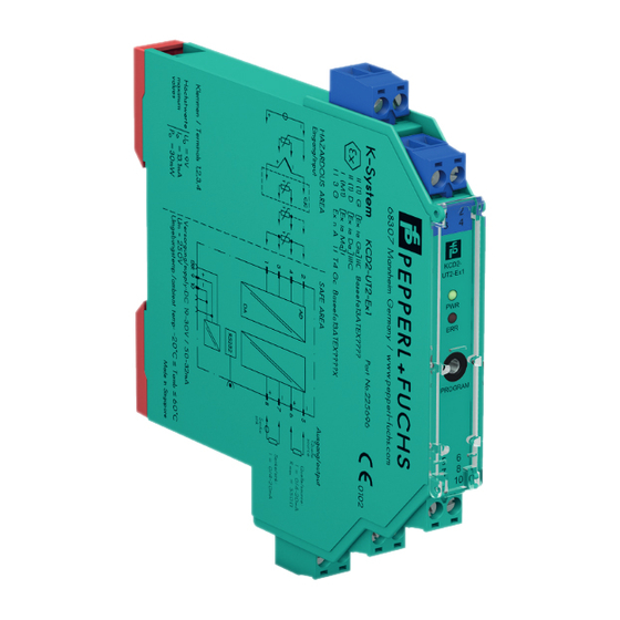
- Page 1 PROCESS AUTOMATION MANUAL Universal Temperature Converter KCD2-UT2-(Ex)1 ISO9001...
- Page 2 Universal Temperature Converter KCD2-UT2-(Ex)1 With regard to the supply of products, the current issue of the following document is applicable: The general terms of delivery for products and services of the electrical industry, as published by the Central Association of the "Elektrotechnik und Elektroindustrie (ZVEI) e.V.", including the supplementary clause "Extended ownership rights".
-
Page 3: Table Of Contents
Universal Temperature Converter KCD2-UT2-(Ex)1 Contents Symbols used in this document ......2 Overview ..........2 Application . -
Page 4: Symbols Used In This Document
Overview Application The devices of the K-System from Pepperl+Fuchs are used to transmit signals between field devices and the process control system or control. Devices with the "Ex" code in their type identifiers are suitable for connection to field devices in the hazardous area. -
Page 5: Versions
Universal Temperature Converter KCD2-UT2-(Ex)1 Overview The temperature converters KCD2- UT2-(Ex)1 of the K-System (referred to as UT2) are used for temperature measurement. Resistance temperature detectors, thermocouples, potentiometers or voltage sources can be connected to the inputs of the converter. The device converts the input signals into proportional current signals or voltage signals. -
Page 6: Safety Instructions
If malfunctions cannot be eliminated, place the devices out of service and protect them from accidental use. The devices may only be repaired directly by the manufacturer Pepperl+Fuchs. Any opening or change in the units are dangerous and are therefore not to be performed. They void any warranty. -
Page 7: Explosion Protection
For secondary explosion protection, that is, measures to avoid the ignition of a surrounding explosive atmosphere by electrical MANUAL equipment, Pepperl+Fuchs will gladly provide you with a copy of the EXPLOSION PROTECTION "Ex-protection manual" for a nominal fee. Please pay particular attention to EN 60079-0, EN 60079-11 and EN 60079-15 or the corresponding national provisions. -
Page 8: Connection
These may be conducted using DIN EN 60079-14 compliant leads into the hazardous area. The non-intrinsically safe field circuit is connected to the green terminals 1 to 4 of the KCD2-UT2-1. The non-intrinsically safe circuit is connected to the green terminals 5 to 10 of the KCD2-UT2-(Ex)1. - Page 9 Universal Temperature Converter KCD2-UT2-(Ex)1 Mounting and connection Input connection (field circuit) You can connect the following sensors: • Resistance temperature sensors Pt10, Pt50, Pt100, Pt500, Pt1000 according to EN 60751: 1995 or GOST 6651-94 Ni 100 according to DIN 43760 ...
- Page 10 Universal Temperature Converter KCD2-UT2-(Ex)1 Mounting and connection Output connection (control circuit) The following connections are available: • Terminals 5/6: analog current output, source • Terminals 7/8: analog current output, sink • Terminals 8/10: power supply 24 V DC KCD2-UT2-Ex1 KC-CJC-** 24 V DC Zone 0, 1, 2 Zone 2...
- Page 11 Universal Temperature Converter KCD2-UT2-(Ex)1 Mounting and connection If a current output is operated as a sink, the voltage across the terminals must be between 5 V and 30 V. An additional resistance is only required if the voltage is above 16.5 V. The resistance must be between (U - 16.5 V)/0.0215 A and (U - 5 V)/0.0215 A (see diagram).
-
Page 12: Controls And Indicators Of The Device
Universal Temperature Converter KCD2-UT2-(Ex)1 Mounting and connection If a current output is operated as a source, the load resistance must be between 0 and 550 . Further information on connecting the UT2 can be found in the data sheet and in the operating instructions for the K-System on our Internet page www.pepperl-fuchs.com/pa (under product search, enter Controls and indicators of the device... -
Page 13: Configuration Tools
Universal Temperature Converter KCD2-UT2-(Ex)1 Configuration tools Configuration tools The temperature transmitters KFD2-UT2-(Ex)*(-1) are parameterised using the configuration tool PACTware The PACTware on-line version can be downloaded free of charge from our internet page www.pepperl-fuchs.com/pa under software/ PACTware. Licensed versions are available at a charge. The device-independent features of the software are described in the "PACTware process automation configuration tool"... -
Page 14: Communication Driver
Universal Temperature Converter KCD2-UT2-(Ex)1 Configuration tools Communication driver In a PACTware project, communication with a UT2 is only possible via the communication driver P2P RS232 FDT. If your project does not yet contain such a driver, please add it to the project from the device catalogue (see "PACTware process automation configuration tool"... -
Page 15: Measured Value
Universal Temperature Converter KCD2-UT2-(Ex)1 Configuration tools Measured value If you have started the communication between PACTware and UT2 (e. g. via Device data Establish connection), you can open the Measured value window via Device data Measured value. It shows the following information on the outputs of the UT2: •... -
Page 16: Simulation
Universal Temperature Converter KCD2-UT2-(Ex)1 Configuration tools Simulation If you have started the communication between PACTware and UT2 (e. g. via Device data Establish connection), you can open the Simulation window via Device data Simulation. The simulation interrupts the normal function of the device! Before starting the simulation, make sure that no dangerous condition in the plant will result. -
Page 17: Diagnosis
• Memory error: error in the memory of the UT2; if this error was caused by an incorrect data transfer, you can eliminate it via Device data Additional functions Service (see section 6.6); otherwise, please contact Pepperl+Fuchs • Internal device error: please contact Pepperl+Fuchs • Simulation mode: see section 6.4 EN - 15... -
Page 18: Service
Universal Temperature Converter KCD2-UT2-(Ex)1 Configuration tools • Undervoltage lockout: the supply voltage is too low for the outputs to work properly, the outputs return 0 mA or 0 V, no matter which fault current/which fault voltage has been selected • Sensor breakage: see section 7.2 •... -
Page 19: Editing Device Data
Universal Temperature Converter KCD2-UT2-(Ex)1 Editing device data Editing device data Any change to device data will change the operation of the device! Before transferring new data into the device, make sure that no danger to the installation will result. Warning If you call the parameters for a UT2 in PACTware (e. - Page 20 Universal Temperature Converter KCD2-UT2-(Ex)1 Editing device data Please specify the frequency of your supply network (50 Hz or 60 Hz) under Net frequency. This way you achieve the best possible suppression of influences of this net frequency on the UT2. The information in menu Description can be edited as desired.
-
Page 21: Menu Input
Universal Temperature Converter KCD2-UT2-(Ex)1 Editing device data Menu Input On the menu Input, you set the parameters for the input at the terminals 1 to 4. EN - 19... - Page 22 Universal Temperature Converter KCD2-UT2-(Ex)1 Editing device data The following parameters can be set: • Sensor (see section 5.2): Resistance temperature detector: Pt10GOST etc. Thermocouple: TXK etc. Potentiometer Voltage • Connection mode (for resistance temperature detectors only, see section 5.2): ...
- Page 23 Universal Temperature Converter KCD2-UT2-(Ex)1 Editing device data • Sensor-short-circuit monitoring (for resistance temperature detectors only) You activate or deactivate monitoring by clicking the respective checkbox ( = selected, = deselected). • Measuring rate (for resistance temperature detectors only) slow ...
-
Page 24: Menu Outpu
Universal Temperature Converter KCD2-UT2-(Ex)1 Editing device data Menu Outpu On the menu Output, you set the parameters for the output at the terminals 5 to 8 (see section 5.2). 22 - EN... - Page 25 Universal Temperature Converter KCD2-UT2-(Ex)1 Editing device data The following parameters can be set: • Characteristic: 4 mA ... 20 mA unlimited 4 mA ... 20 mA (NE 43) 4 mA ... 20 mA limited 0 mA ... 20 mA For information on the behaviour of the current output at the different settings, see section 7.4.
-
Page 26: Behaviour Of The Current Output
Universal Temperature Converter KCD2-UT2-(Ex)1 Editing device data Behaviour of the current output The linear behaviour outside the measurement range described in the following only results if temperature values ranging between the minimum value and the maximum value of the selected sensor correspond to the current values. - Page 27 Universal Temperature Converter KCD2-UT2-(Ex)1 Editing device data 7.4.2 Setting 4 mA ... 20 mA (NE 43) 20.5 20.0 103 -1.25 % meas. Start value End value range At this setting, the start value of the measurement range is converted to 4 mA and the end value to 20 mA.
- Page 28 Universal Temperature Converter KCD2-UT2-(Ex)1 Editing device data 7.4.4 Setting 0 mA ... 20 mA 20.5 20.0 102.5 % meas. End value range Start value At this setting, the start value of the measurement range is converted to 0 mA and the end value to 20 mA.
- Page 29 Universal Temperature Converter KCD2-UT2-(Ex)1 Editing device data 7.4.5 Fault current The following table shows the values of the current output during a fault, depending on the settings. Setting Characteristic Characteristics Characteristic 4 mA ... 20 mA 4 mA ... 20 mA (NE 43) 0 mA ...
- Page 30 PROCESS AUTOMATION – PROTECTING YOUR PROCESS Worldwide Headquarters Pepperl+Fuchs GmbH 68307 Mannheim · Germany Tel. +49 621 776-0 E-Mail: info@de.pepperl-fuchs.com For the Pepperl+Fuchs representative closest to you check www.pepperl-fuchs.com/contact www.pepperl-fuchs.com 813968 TDOCT-3514_ENG Subject to modifications Copyright PEPPERL+FUCHS · Printed in Germany...
Need help?
Do you have a question about the KCD2-UT2-1 and is the answer not in the manual?
Questions and answers