Table of Contents
Advertisement
Quick Links
Water Specialist
WS2H and WS3 Control Valve
Manual
HYDROCARBONS SUCH AS VASELINE®, PETROLEUM JELLY, KEROSENE, BENZENE,
GASOLINE, ETC., WILL DAMAGE PRODUCTS THAT CONTAIN O-RINGS OR PLASTIC
COMPONENTS. EXPOSURE TO SUCH HYDROCARBONS MAY CAUSE THE PRODUCTS
TO LEAK. DO NOT USE CLACK CONTROL VALVE PRODUCT(S) ON WATER SUPPLIES
THAT CONTAIN HYDROCARBONS SUCH AS KEROSENE, BENZENE, GASOLINE, ETC.
Advertisement
Table of Contents

Related Manuals for Water Specialist WS2H


Summary of Contents for Water Specialist WS2H
- Page 1 Water Specialist WS2H and WS3 Control Valve Manual HYDROCARBONS SUCH AS VASELINE®, PETROLEUM JELLY, KEROSENE, BENZENE, GASOLINE, ETC., WILL DAMAGE PRODUCTS THAT CONTAIN O-RINGS OR PLASTIC COMPONENTS. EXPOSURE TO SUCH HYDROCARBONS MAY CAUSE THE PRODUCTS TO LEAK. DO NOT USE CLACK CONTROL VALVE PRODUCT(S) ON WATER SUPPLIES...
- Page 2 Page 2 WS2H and WS3 Manual...
-
Page 3: Table Of Contents
WS3 Drive Cap Assembly, Downfl ow Piston, Regenerant Piston, Spacer Stack Assembly, Drive Back Plate and Main Body..........43 WS2H and WS3 Brine Valve Body and Injector Components ........44 Standard Injector Graphs ....................45 V3064 WS2H/2QC 4 INCH BASE ASY................47 V3055 WS2H/2QC 6 INCH FLANGE BASE ASY ............ -
Page 4: General Specifications And Pre-Installation Checklist
Flow Range 1.5 – 125 gpm 3.5 – 350 gpm (13.3 – 1325 lpm) (5.7 – 473 lpm) WS2H and WS3 Valves: Variable - Shipped from Factory with 2.2 gpm Regenerant Refi ll Rate (8.33 lpm) Injectors WS2H & WS3 Valves: See Injector Graphs V3010-2A through 2H Brine Line Adapters Included 1”... -
Page 5: Wiring For Custom Power Adapter
WS2H and WS3 Manual Page 5 WIRING FOR CUSTOM POWER ADAPTER Pin 1 1. Cable should be one unshielded pair of 22AWG, UV resistant Black wire UL2464 compliant wire. 2. Connector details: a. Terminate end with one Hirose black housing, P/N DF3-4S-2C and four Hirose pins, P/N DF3-22SC. -
Page 6: Main Pc Board
Page 6 WS2H and WS3 Manual MAIN PC BOARD POD Display Connection Power Supply Programming Port COMM IN Flow Meter AUX Input COMM OUT Battery USB Port Drive Motor Expansion port 1 Expansion port 2 AUX Drive Motor Bypass Motor... -
Page 7: Typical System Examples
WS2H and WS3 Manual Page 7 TYPICAL SYSTEM EXAMPLES Twin Tank System, Simple Alternator (Sharing a MAV) System consists of 2 power heads, 1 communication cable and 1 MAV Electrical Connections: • The MAV’s motor wire is connected to the 2-pin connector labeled BYPASS on Unit 2 (Unit B) PC board •... - Page 8 Page 8 WS2H and WS3 Manual TYPICAL SYSTEM EXAMPLES (CONTINUED) Multi-tank System, 3 Unit shown System consists of 3 power heads, 2 communication cables and 3 No Hard Water Bypass (Isolation) valves Electrical Connections: • Each unit’s isolation valve motor wire is connected to the 2-pin connector labeled BYPASS on each unit’s PC board.
-
Page 9: Button Function And Programming Key Sequence
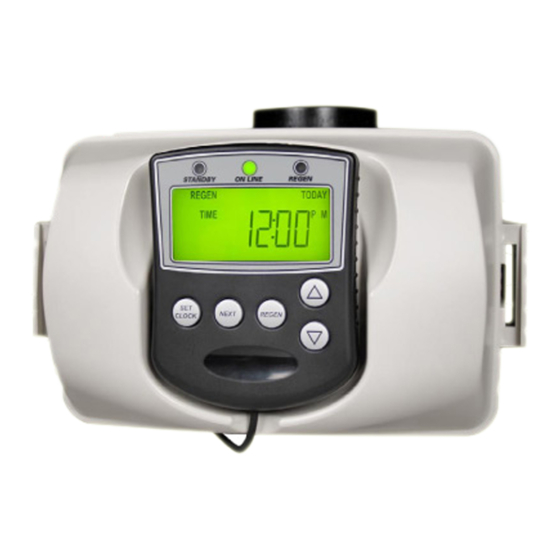
WS2H and WS3 Manual Page 9 BUTTON FUNCTION AND PROGRAMMING KEY SEQUENCE STANDBY ON LINE REGEN Standby LED Online LED Regen LED • Signals that a unit • Signals that a unit is • Signals that a unit is is not in service, or... -
Page 10: Programming Quick Reference
Page 10 WS2H and WS3 Manual PROGRAMMING QUICK REFERENCE GRAINS x1000 Recommended System Setup Sequence 1. Connect all wiring and communication cables. 2. Apply power. 3. Select System Setup from the Main Setup Menu. 4. Select the correct language to use in System Setup 1. - Page 11 WS2H and WS3 Manual Page 11 PROGRAMMING QUICK REFERENCE List Of Error Codes Code Description 1001 No Encoder Pulses 1002 Unexpected Stall, Main Drive 1003 Run Time Too Long, Main Drive 14001 Message Queue Full 15003 Run Time Too Long, Bypass Drive...
-
Page 12: Typical User Screens
Page 12 WS2H and WS3 Manual TYPICAL USER SCREENS USER 1 - Capacity Remaining USER 1 • Displays the units current capacity remaining • This screen does not display on units with volumetric capacity turned off • Can be manually decremented by holding the down arrow... - Page 13 WS2H and WS3 Manual Page 13 TYPICAL USER SCREENS (CONTINUED) USER 6 – Flow Rate, System USER 6 • Displays the current combined fl ow rate of all the units in the system • This screen does not display on single tank units, or systems with volumetric capacity turned USER 7 –...
-
Page 14: Setting Time Of Day And Date
Page 14 WS2H and WS3 Manual SETTING TIME OF DAY AND DATE SET TIME AND DATE Accessed by pressing Set Clock while in the User Screens. Use UP or DOWN arrows to scroll through the available settings. RETURN TO NORMAL OPERATION NOTIFICATIONS •... -
Page 15: Main Menu
WS2H and WS3 Manual Page 15 MAIN MENU SCREEN Accessed the Main Menu is done by pressing NEXT and DOWN simultaneously for >3 seconds while in one of the user screens. INSTALLER SETUP - Setup items under the Installer Setup Screens section... -
Page 16: System Setup Screens
Page 16 WS2H and WS3 Manual SYSTEM SETUP SCREENS Accessed by pressing NEXT and DOWN simultaneously for >3 seconds and selecting SYSTEM SETUP from the Main Menu. • System setup screens will be locked on units determined to be a slaves of a system - Slave units need to be reset, “Next”... - Page 17 WS2H and WS3 Manual Page 17 SYSTEM SETUP SCREENS (CONTINUED) • Delayed systems will fl ag “lead” units based on “lag” capacity, but will not alternate with remaining capacity until the next available delayed time. - Day over ride • 1 day; 1 unit will regen •...
- Page 18 Page 18 WS2H and WS3 Manual SYSTEM SETUP SCREENS (CONTINUED) Separate Source • Each unit has isolation to control system operation and will not supply service water during regeneration • Drive timing will keep units isolated through the entire regeneration sequence Simple Alt Sharing MAV •...
- Page 19 WS2H and WS3 Manual Page 19 SYSTEM SETUP SCREENS (CONTINUED) SYSTEM SETUP 9 - Regeneration control SYSTEM SETUP 9 Delayed 1 – 4 • Delays regeneration of units upon reaching 0 gallons capacity • Allows setting of up to 4 regeneration windows per day •...
- Page 20 Page 20 WS2H and WS3 Manual SYSTEM SETUP SCREENS (CONTINUED) SYSTEM SETUP 11A SYSTEM SETUP 11A - Level Input option selected SET METER PULSES Set a time duration of switch closure when Level option is selected PULSES PER GALLON SYSTEM SETUP 12 - Meter Size Selection SYSTEM SETUP 12 2”...
-
Page 21: Cycle Setup Screens
WS2H and WS3 Manual Page 21 CYCLE SETUP SCREENS Accessed by pressing NEXT and DOWN simultaneously for >3 seconds and selecting CYCLE SETUP from the Main Menu. CYCLE SETUP 1A CYCLE SETUP 1A Select fi rst step of the primary regeneration cycle. - Page 22 Page 22 WS2H and WS3 Manual CYCLE SETUP SCREENS (CONTINUED) CYCLE SETUP 3C CYCLE SETUP 3C Select the second step of the secondary regeneration cycle. SECONDARY CYCLE STEP 6 FILL HOLD Continue selecting the step type and entering the duration until the secondary regeneration SLOW RINSE cycle has been defi ned.
-
Page 23: Expansion Setup Screens
WS2H and WS3 Manual Page 23 EXPANSION SETUP SCREENS Accessed by pressing NEXT and DOWN simultaneously for >3 seconds and selecting EXPANSION SETUP from the Main Menu. EXPANSION SETUP 1 EXPANSION SETUP 1 Select the expanison port, 1 or 2, that you will modify. - Page 24 Page 24 WS2H and WS3 Manual EXPANSION SETUP SCREENS (CONTINUED) EXPANSION SETUP 2B-1A SERVICE VOLUME EXPANSION SETUP 2B-1A • Enter the volume to energize the relay at EXPANSION SETUP 2B-1B SERVICE VOLUME EXPANSION SETUP 2B-1B • Enter the total time to keep the relay energized for...
- Page 25 WS2H and WS3 Manual Page 25 EXPANSION SETUP SCREENS (CONTINUED) EXPANSION SETUP 2B-5A REGEN VOLUME EXPANSION SETUP 2B-5A • Enter the volume to energize the relay at EXPANSION SETUP 2B-5B REGEN VOLUME EXPANSION SETUP 2B-5B • Enter the total time to keep the relay energized for...
-
Page 26: Installer Setup Screens
Page 26 WS2H and WS3 Manual INSTALLER SETUP SCREENS Accessed by pressing NEXT and DOWN simultaneously for >3 seconds and selecting IN- STALLER SETUP from the Main Menu. INSTALLER 1 – Set hardness INSTALLER 1 Set the inlet water hardness, in grains. - Page 27 WS2H and WS3 Manual Page 27 INSTALLER SETUP SCREENS (CONTINUED) INSTALLER 6 – Set Delayed Regeneration Close Time Minute INSTALLER 6 • Set delayed time of regeneration, minute • When confi gured for multiple delayed regeneration windows, repeat Installer steps 3 through 6 for each additional window INSTALLER 7 –...
-
Page 28: Diagnostic Screens
Page 28 WS2H and WS3 Manual DIAGNOSTIC SCREENS Accessed by pressing UP and DOWN simultaneously for >3 seconds. DIAGNOSTIC 1 DIAGNOSTIC 1 Days since the last regeneration. All Diagnostic History screens are resettable with the History Reset sequence while in the Diagnostics 1 screen. - Page 29 WS2H and WS3 Manual Page 29 DIAGNOSTIC SCREENS (CONTINUED) DIAGNOSTIC 4A DIAGNOSTIC 4A Hourly history of volume use. Use the UP and DOWN arrow to select the hours of the day. Returns user back to USE Day 0 in Diagnostic 4 screen.
- Page 30 Page 30 WS2H and WS3 Manual DIAGNOSTIC SCREENS (CONTINUED) DIAGNOSTICS 7A DIAGNOSTIC 7A Total system hourly history of volume use UP and DOWN arrow to select the hours of the day from Screen 7. Returns user back to USE Day 0 in Diagnostic 7 screen.
-
Page 31: Valve History
WS2H and WS3 Manual Page 31 VALVE HISTORY Accessed by pressing UP and DOWN simultaneously for >3 seconds, then by pressing UP and DOWN simultaneously again for >3 seconds. Non-Resettable HISTORY 1 HISTORY 1 Total days since startup. Time only accumulates while the unit is plugged in. -
Page 32: Custom Motorized Drive Timing
Page 32 WS2H and WS3 Manual CUSTOM MOTORIZED DRIVE TIMING • Used to alter the standard timing sequence of the motorized isolation valve for SET BYPASS CONTROL HARD WATER BYPASS complete custom timing of the drive circuits NO HARD WATER BYPASS SEPARATE SOURCE INLET - Setup procedure applies to both the “Bypass”... -
Page 33: Modbus Information
Page 33 MODBUS INFORMATION The WS2H/3 is capable of using Modbus through a full-duplex RS485 connection using the COMM IN connector on the fi rst control in a system. The baud rate must be set to 115200. To enable Modbus, select System Setup 3 (Set Number of Units) and hold the UP and DOWN arrows for >3s. Once the screen appears for enabling Modbus, select “Yes”... -
Page 34: Installation
Page 34 WS2H and WS3 Manual INSTALLATION WS2H CONTROL VALVE TOP VIEW BRINE/REFILL INLET DRAIN INTERNAL OUTLET FLOW METER WS3 CONTROL VALVE TOP VIEW BRINE/REFILL DRAIN INLET OUTLET... - Page 35 Clean up water spills. Allow two feet of clearance to service WS2H and WS3 valves. The valve will withstand transportation and storage temperatures of -13 ˚F (-25 ˚C) to 131 ˚F (55 ˚C) and for short periods up to 158 ˚F (70 ˚C).
- Page 36 7. Drain: Verify that the drain can handle the backwash rate of the water conditioner. Correctly size the drain line and install an appropriately sized drain line fl ow control. For WS2H and WS3 valves a drain line fl ow control are NOT supplied with a valve.
-
Page 37: Installation Summary
WS2H and WS3 Manual Page 37 INSTALLATION SUMMARY Installation Date: ___________________________________________ Installation Location: _______________________________________ Installer(s): ________________________________________________ Phone Number: Application Type: (Softener) __________Other: _____________ Water Source: ____________________________________________ Water Test Results: Hardness: ______________Iron: _______________pH: ___________ Other: ____________________________________________________ __________________________________________________________ Misc: Service Flow Rates: min. ______________ max. -
Page 38: Cycle Positions / Flow Diagrams
Page 38 WS2H and WS3 Manual CYCLE POSITIONS / FLOW DIAGRAMS SERVICE Raw Water Inlet Treated Water Outlet BACKWASH Backwash Water to Drain Raw Water Raw/Hard Water is bypassed Inlet during regeneration... - Page 39 WS2H and WS3 Manual Page 39 CYCLE POSITIONS / FLOW DIAGRAMS (CONTINUED) DRAW Backwash Water to Drain Raw Water Raw/Hard Water is bypassed Inlet during regeneration Regenerant solution being drawn in Injector feed water from Raw Water Inlet supply SLOW RINSE...
- Page 40 Page 40 WS2H and WS3 Manual CYCLE POSITIONS / FLOW DIAGRAMS (CONTINUED) RINSE Rinse Water to Drain Raw Water Raw/Hard Water is bypassed Inlet during regeneration SOFT WATER REFILL Raw Water Inlet Treated Water Supply Treated Water to Regenerant Tank...
-
Page 41: Front Cover And Drive Assembly
Description Quantity V3068 WS2H/3 POD FRONT/BACK COVERS V3082-01 WS2H/3 GRAPHICS POD ASY W/BRD* Optional V3241-02BOARD WS2H/3 DISPLAY GRPH POD PCB REPL V3248-01 WS2H/3 GRAPHICS POD CABLE V3242-02BOARD WS2H/3 VLV W/ MODBUS PCB REPL V3224-01R WS2H/3 COVER ASY PLATINUM V3107-01 WS1 MOTOR ASY... -
Page 42: Ws2H Drive Cap Assembly, Downfl Ow Piston, Regenerant Piston, Spacer Stack Assembly, Drive Back Plate, Main Body And Meter
Page 42 WS2H and WS3 Manual WS2H DRIVE CAP ASSEMBLY, DOWNFLOW PISTON, REGENERANT PISTON, SPACER STACK ASSEMBLY, DRIVE BACK PLATE, MAIN BODY AND METER Drawing No. Order No. Description Quantity V3275 WS2H/3 SCW BSHD SS3/8-16X2-1/4 (7/32” hex allen wrench required) -
Page 43: Ws3 Drive Cap Assembly, Downflow Piston, Regenerant Piston, Spacer Stack Assembly, Drive Back Plate And Main Body
Not Shown V3672 TOP BAFFLE DFSR CLACK 3/90MM *V3091 WS3 BASE CLAMP ASY includes a V3276 WS2H/3 BOLT HEX SS 5/16-18X1-3/4 and V3269 WS2H/3 NUT 5/16-18 SS HEX. **V3238-01 Brine Piston is used for Backwash Only valves. B Indicates BSPT N Indicates NPT Install V3672 upper diffuser (not shown) when using the 6”... -
Page 44: Ws2H And Ws3 Brine Valve Body And Injector Components
**V3670-01 WS3 INJECTOR TUBE DOWNFLOW ASY contains a V3285 O-RING 213, V3286 O-RING 216 and a V3163 O-RING 019. ***Any V3162-XXX fl ow control may be used. V3237-01 WS2H SOFTFILL TUBE ASY contains a V3155 O-RING 112, V3287 O-RING 110 and a V3288 O-RING 206. -
Page 45: Standard Injector Graphs
WS2H and WS3 Manual Page 45 STANDARD INJECTOR GRAPHS Order No. V3010-2B Order No. V3010-2A US Units US Units Total Total Slow Rinse Slow Rinse Draw Draw Pressure (psi) Pressure (psi) Order No. V3010-2D Order No. V3010-2C US Units US Units... - Page 46 Page 46 WS2H and WS3 Manual STANDARD INJECTOR GRAPHS (CONTINUED) Order No. V3010-2A Order No. V3010-2B Metric Units Metric Units Total Total Slow Rinse Slow Rinse Draw Draw Pressure (kPa) Pressure (kPa) Order No. V3010-2C Order No. V3010-2D Metric Units...
-
Page 47: V3064 Ws2H/2Qc 4 Inch Base Asy
Drawing No. Order No. Description Quantity V3202-01 WS2H BASE V3419 O-RING 347 V3055 WS2H/2QC 6 INCH FLANGE BASE ASY or V3090 WS3 6 INCH FLANGE BASE ASY Quantity Drawing Order Description V3055 V3090 V3444 WS2H SCREW HEXCAP 5/16-18X2 SS V3293... -
Page 48: Drain Line Flow Controls
Page 48 WS2H and WS3 Manual DRAIN LINE FLOW CONTROLS All drain line fl ow control housings are shipped without fl ow control washers. See drain line fl ow control washer section for available fl ow selections. PVC Elbow, 0.7 - 10 GPM... -
Page 49: M X F Stainless Steel, 0.7 - 150 Gpm
WS2H and WS3 Manual Page 49 M X F STAINLESS STEEL, 0.7 – 150 GPM Quantity Drawing Order Description V3051 V3051BSPT V3052 WS2 DLFC Retainer Asy V3245 WS2 DLFC Flange Inlet NPT V3245BSPT WS2 DLFC Flange Inlet BSPT V3246 WS2 DLFC Flange Outlet NPT... -
Page 50: Mxf Stainless Steel, 9-225 Gpm
Page 50 WS2H and WS3 Manual MXF STAINLESS STEEL, 9-225 GPM Quantity Drawing Order No. Description V3764 V3764BSPT V3765-01 WS3 DLFC HOUSING NPT V3765BSPT-01 WS3 DLFC HOUSING BSPT V3766 WS3 DLFC RETAINER V3767 WS3 DLFC RETAINER COVER V3768 WS3 DLFC RETAINER RING... -
Page 51: Drain Line Flow Control Washers
WS2H and WS3 Manual Page 51 DRAIN LINE FLOW CONTROL WASHERS V3162-XXX Order No. Description V3162-xx Flow Rate V3162-007 .7 GPM Drain line fl ow control Identification V3162-010 1.0 GPM Drain line fl ow control 5/8" V3162-013 1.3 GPM Drain line fl ow control V3162-017 1.7 GPM Drain line fl ow control... -
Page 52: Ws2H/ Ws3 Trouble Shooting Guide
Page 52 WS2H and WS3 Manual WS2H/ WS3 TROUBLE SHOOTING GUIDE Problem Possible Cause Solution a. No power at electric outlet a. Repair outlet or use working outlet b. Control valve Power Adapter not b. Plug Power Adapter into outlet or... - Page 53 WS2H and WS3 Manual Page 53 WS2H/ WS3 TROUBLE SHOOTING GUIDE (CONTINUED) Problem Possible Cause Solution a. Bypass/ isolation valves in bypass a. Turn bypass/ isolation valves handles position to place in service position b. Meter is not connected to meter b.
- Page 54 Page 54 WS2H and WS3 Manual WS2H/ WS3 TROUBLE SHOOTING GUIDE (CONTINUED) Problem Possible Cause Solution a. Low water pressure a. Check incoming water pressure – water pressure must remain at minimum of 25 psi b. Plugged, fouled, or incorrect injector b.
- Page 55 WS2H and WS3 Manual Page 55 WS2H/ WS3 TROUBLE SHOOTING GUIDE (CONTINUED) Problem Possible Cause Solution a. Motor not inserted fully to engage a. Disconnect power, make sure motor pinion, motor wires broken or is fully engaged, check for broken...
- Page 56 Page 56 WS2H and WS3 Manual WS2H/ WS3 TROUBLE SHOOTING GUIDE (CONTINUED) Problem Possible Cause Solution a. Motor failure during a regeneration a. Check motor connections then Press NEXT and REGEN buttons for about 3 seconds to resynchronize software with piston position.
- Page 57 WS2H and WS3 Manual Page 57 WS2H/ WS3 TROUBLE SHOOTING GUIDE (CONTINUED) Possible Cause Solution Problem 20. Err – 15010 = Motorized a. Foreign material is lodged in a. Open up Motorized Bypass or MAV Bypass or MAV for NHBP...
- Page 58 Page 58 WS2H and WS3 Manual WS2H/ WS3 TROUBLE SHOOTING GUIDE (CONTINUED) Problem Possible Cause Solution Correct all errors on satellite units before attempting to reset error on master a. System is programmed for the a. Pressing any button while in the # of...
- Page 59 WS2H and WS3 Manual Page 59 WS2H/ WS3 TROUBLE SHOOTING GUIDE (CONTINUED) Problem Possible Cause Solution a. Foreign material is lodged in MAV a. Open up MAV for separate source for separate source valve and check for foreign material. Press...
- Page 60 1/13/2021 Page 42: V3201-03 WS2H BODY W/V3468-04 PLUG V3201BSPT-03 WS2H BSPT BODY W/V3465 PLUG 1/29/2021 Page 5 - Updated drawing Page 6 - Updated drawing Page 7 and 8 - Updated board drawings Page 11 – Updated History 4 screen Page 31 –...
Need help?
Do you have a question about the WS2H and is the answer not in the manual?
Questions and answers