Advertisement
Water Specialist
1" Control Valve Series Model: WS1TC
1.25" Control Valve Series Model: WS1.25TC
Operation and Instruction Manual for OEM Only.
Please Note: This operation and instruction manual is for the training of
the OEM and for the OEM to use to train their customers. This document
is not to be used as the complete system manual.
Advertisement
Table of Contents

Related Manuals for Water Specialist WS1TC


Summary of Contents for Water Specialist WS1TC
- Page 1 Water Specialist 1” Control Valve Series Model: WS1TC 1.25” Control Valve Series Model: WS1.25TC Operation and Instruction Manual for OEM Only. Please Note: This operation and instruction manual is for the training of the OEM and for the OEM to use to train their customers. This document...
-
Page 2: Normal Operation
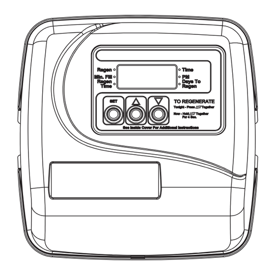
MANUAL REGENERATION Arrow will point to Regen if a regeneration is expected “Tonight.” NOTE: For softeners, if brine tank does not contain salt, fi ll with salt and wait at least 2 hours before regeneration. If you need to initiate a manual regeneration, either immediately, or tonight at the preprogrammed time (typically 2 a.m.), complete the following steps. -
Page 3: Table Of Contents
User Displays/Settings .............................10 Drawings and Part Numbers Front Cover and Drive Assembly ........................12 WS1TC Drive Cap, Pistons and Spacer Stack ....................13 WS1.25TC Drive Cap, Pistons and Spacer Stack ...................14 WS1 & WS1.25 Identifi cation Figure ......................15 FOR INFORMATION COMMON TO ALL 1” & 1.25” CONTROL VALVES... -
Page 4: Control Valve Function And Cycles Of Operation
Page 4 WS1TC & WS1.25 TC Manual Control Valve Function and Cycles of Operation This glass fi lled Noryl (or equivalent) fully automatic control valve is designed as the primary control center to direct and regulate all cycles of a downfl ow regeneration water softener or fi lter. - Page 5 WS1TC & WS1.25 TC Manual Page 5 • The user can initiate manual regeneration. The user has the option to request the manual regeneration at the delayed regeneration time or to have the regeneration occur immediately. Simultaneously press to start a regeneration at the next delayed ▲...
-
Page 6: Oem General Programming Instructions
Page 6 WS1TC & WS1.25 TC Manual OEM General Instructions The control valve offers multiple procedures that allow the valve to be modifi ed to suit the needs of the installation. These procedures are: • OEM System Setup • Installer Displays & Settings (either 1-99 Days Between Regeneration option or 7-Day option) •... - Page 7 WS1TC & WS1.25 TC Manual Page 7 STEP 4SS STEP 4SS - Use ▲ or ▼ to switch between: • 1-99 Days Between Regeneration - Regeneration is determined by the number of days that have passed since the last regeneration scheduled.
-
Page 8: Installer Displays/Settings
Page 8 WS1TC & WS1.25 TC Manual Installer Displays & Settings (1-99 Days Between Regeneration Option) STEP 1ID STEP 1ID – From normal mode, press SET + ▲ buttons simultaneously for 3 seconds and release. STEP 2ID STEP 2ID – Regeneration Time Hour: Set the time for regeneration to start using ▲ or ▼. Press SET to go to the next step. - Page 9 WS1TC & WS1.25 TC Manual Page 9 STEP 5I7 STEP 5I7 – Sunday Regeneration: To regenerate on Sunday use ▲ or ▼ until the arrow points to Regen. If the arrow does not point to Regen a regeneration will not occur on Sunday. Press SET to go to STEP 6I7.
-
Page 10: User Displays/Settings
Page 10 WS1TC & WS1.25 TC Manual User Displays General Operation When the system is operating one of two displays will be shown. Pressing ▲ or ▼ will alternate between the displays. One of the displays is always the current time of day. The second display is the days remaining until the next regeneration. - Page 11 WS1TC & WS1.25 TC Manual Page 11 Set Time of Day STEP 1U STEP 1U – Press SET STEP 2U STEP 2U – Current time: Adjust hour with ▲ or ▼. With 60 Hz line frequency detection on power-up, timekeeping is 12 hour with PM indicator. With 50 Hz line frequency detection on power-up, timekeeping is 24 hour without the PM indicator.
-
Page 12: Front Cover And Drive Assembly
Page 12 WS1TC & WS1.25 TC Manual Front Cover and Drive Assembly Drawing No. Order No. Description Quantity V3175TC-01 WS1TC FRONT COVER ASY V3107-01 WS1 MOTOR ASY V3106-01 WS1 DRIVE BRACKET & SPRING CLIP V3818TC WS1TC PC BOARD 4-DIGIT V3110... -
Page 13: Ws1Tc Drive Cap, Pistons And Spacer Stack
WS1TC & WS1.25 TC Manual Page 13 WS1TC Drive Cap Assembly, Downfl ow Piston, Regenerant Piston and Spacer Stack Assembly Drawing No. Order No. Description Quantity V3005 WS1 Spacer Stack Assembly V3004 Drive Cap ASY V3178 WS1 Drive Back Plate V3011 WS1 Piston Downfl... -
Page 14: Ws1.25Tc Drive Cap, Pistons And Spacer Stack
Page 14 WS1TC & WS1.25 TC Manual WS1.25TC Drive Cap Assembly, Downfl ow Piston, Regenerant Piston and Spacer Stack Assembly Drawing No. Order No. Description Quantity V3430 WS1.5 Spacer Stack Assembly V3004 Drive Cap ASY V3178 WS1 Drive Back Plate V3407 WS1.5 Piston Downfl... -
Page 15: Ws1 & Ws1.25 Identifi Cation Figure
WS1TC & WS1.25 TC Manual Page 15 WS1 & WS1.25 Identifi cation Figure WS1 with 1.050" Distributor Tube Opening Identifi cation Spacer Color: Grey 1.25" Black Plug 1.25" Note: The WS1 downfl ow piston is a solid amber color. WS1.25 with 1.32" Distributor Tube Opening Identifi cation... - Page 16 Page 16 WS1TC & WS1.25 TC Manual Form No. V3115TC-04 – 4/7/2014 U.S. Patents: 6,402,944 • 6,444,127 • 6,776,901...
Need help?
Do you have a question about the WS1TC and is the answer not in the manual?
Questions and answers