Table of Contents
Advertisement
Quick Links
Water Specialist
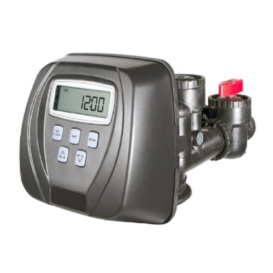
1" Control Valve Series Model: WS1CC
1.25" Control Valve Series Model: WS1.25CC
Operation and Instruction Manual for OEM Only.
Please Note: This operation and instruction manual is for the training of the
OEM and for the OEM to use to train their customers. This document is not
to be used as the complete system manual.
Advertisement
Table of Contents

Related Manuals for Water Specialist WS1CC


Summary of Contents for Water Specialist WS1CC
- Page 1 Water Specialist 1” Control Valve Series Model: WS1CC 1.25” Control Valve Series Model: WS1.25CC Operation and Instruction Manual for OEM Only. Please Note: This operation and instruction manual is for the training of the OEM and for the OEM to use to train their customers. This document is not...
-
Page 3: Table Of Contents
Front Cover and Drive Assembly ............................30 WS1CC Drive Cap Assembly, Downfl ow Piston, Upfl ow Piston, Regenerant Piston and Spacer Stack Assembly ..31 WS1.25CC Drive Cap Assembly, Downfl ow Piston, Regenerant Piston and Spacer Stack Assembly ......32 Injector Cap, Injector Screen, Injector, Plug and O-ring .................... -
Page 4: Introduction
Page 4 WS1CC & WS1.25CC Manual Introduction This manual is about a control valve to be used on water softeners or water fi lters. The manual is designed to aid water treatment equipment manufacturers in the selection of the various control valve options. Information in this manual is different than what is needed for installation and servicing of a particular water treatment system. -
Page 5: Specifi Cations Which Must Be Included In Oem's Manual
- 1¼” & 1½” brass sweat fi tting - 1¼” & 1½” PVC solvent fi tting - ¾” or 1” PEX fi ttings Distributor Tube Opening WS1CC Valve 1.05” outside diameter (¾” NPS) 1.32” outside diameter (1” NPS) Distributor Tube Opening WS1.25CC Valve... -
Page 6: Control Valve Function And Cycles Of Operation
The WS1.25CC control valve is only available in downfl ow regeneration. When the WS1CC or WS1.25CC control valve is set up as a fi lter, the control valve can be set to perform downfl ow regeneration or simply backwash. - Page 7 10. Bypass Valve (optional) Note: The WS1CC & WS1.25CC share many of the same components. Refer to Figure 6 for control valve identifi cation. See Installer Display Settings, OEM Softener System Setup and OEM Filter System Setup for explanations of Day Override and Gallon Capacity.
-
Page 8: Drive Assembly
(U.S. Patent 6444127). One of three main pistons is always used: 1. A 1.25" diameter downfl ow piston is used when the WS1CC control valve is used as a downfl ow softener, regenerating fi lter or non-regenerating fi lter. -
Page 9: Injector Cap, Screen, Injector Plug And Injector
• no regenerant WS1CC & WS1.25CC (both the DN and UP holes have injector plugs installed) and plug installed for the refi ll elbow NOTE: It is not recommended to fi eld convert valves from upfl ow to downfl ow and vice versa. Separate areas in the valve supply water to the injector for upfl... -
Page 10: Drain Line Flow Control And Fitting Assembly
Page 10 WS1CC & WS1.25CC Manual The refi ll fl ow control assembly is installed in an easy to access refi ll elbow located on top of the control valve. The refi ll fl ow control assembly is attached to the control valve with a locking clip. The locking clip allows the elbow to rotate 270 degrees so the outlet can be orientated towards the regenerant tank. -
Page 11: Water Meter Or Meter Plug
WS1CC & WS1.25CC Manual Page 11 Water Meter or Meter Plug The water meter is installed on the outlet side of the control valve. The water meter uses a turbine to measure gallons of treated water. The turbine rotates with the fl ow of water and reports its rate of rotation through Hall effect circuitry to the printed circuit (PC) board. -
Page 12: Bypass Valve
Page 12 WS1CC & WS1.25CC Manual Bypass Valve The bypass valve is typically used to isolate the control valve from the plumbing system’s water pressure in order to perform control valve repairs or maintenance. The WS1 bypass valve is particularly unique in the water treatment industry due to its versatility and state of the art design features. - Page 13 WS1CC & WS1.25CC Manual Page 13 Figure 1 Figure 2 Figure 3 Figure 4...
-
Page 14: Oem General Instructions
Page 14 WS1CC & WS1.25CC Manual OEM General Instructions The control valve offers multiple procedures that allow the valve to be modifi ed to suit the needs of the installation. These procedures are: • OEM Cycle Sequence • OEM Softener System Setup •... - Page 15 WS1CC & WS1.25CC Manual Page 15 Step 1CS – Press NEXT and ▼ simultaneously for 3 seconds and release. Then press NEXT and ▼ STEP 1CS simultaneously for 3 seconds and release. If screen in Step 2CS does not appear in 5 seconds the lock on the valve is activated.
-
Page 16: Oem Softener System Setup
Page 16 WS1CC & WS1.25CC Manual STEP 6CS Step 6CS - Press the ▼ or ▲ buttons until RINSE appears. Press NEXT to go to Step 7CS. Press REGEN to return to previous step. STEP 7CS Step 7CS - Press the ▼ or ▲ buttons until FILL appears. Press NEXT to go to Step 8CS. - Page 17 WS1CC & WS1.25CC Manual Page 17 Step 4S – Select the time for the second cycle (which in this example is dn BRINE) using the ▼ or ▲ STEP 4S button. Press NEXT to go to Step 5S. Press REGEN to return to previous step.
- Page 18 Page 18 WS1CC & WS1.25CC Manual Table 8 Softener Setting Options Gallons Regeneration Result Capacity Time Option Override Reserve capacity automatically estimated. AUTO NORMAL Regeneration occurs when gallons capacity falls below the reserve capacity at the next Regen Set Time.
-
Page 19: Oem Filter System Setup
WS1CC & WS1.25CC Manual Page 19 OEM Filter System Setup In OEM Filter System Setup the OEM chooses the time for the cycles selected in OEM Cycle Sequence and specifi es other operating parameters for the system. The upper and lower limits of the allowable values for the cycles are as follows:... - Page 20 Page 20 WS1CC & WS1.25CC Manual Step 7F – Set Gallons Capacity using the ▼ or ▲ button. If value is set to: STEP 7F • “oFF” regeneration will be based solely on the day override set (see Installer Display/Settings Step 3I);...
-
Page 21: Installer Display Settings
WS1CC & WS1.25CC Manual Page 21 Installer Display Settings STEP 1I STEP 1I - Press NEXT and ▲ simultaneously for 3 seconds. STEP 2I STEP 2I – Hardness: Set the amount of hardness in grains of hardness as calcium carbonate per gallon using the ▼... -
Page 22: User Display Settings
Page 22 WS1CC & WS1.25CC Manual User Display Settings General Operation When the system is operating, one of fi ve displays may be ➟ shown. Pressing NEXT will alternate between the displays. One of the displays is always the current time of day. The second display is one of the following: days remaining or volume remaining. - Page 23 WS1CC & WS1.25CC Manual Page 23 Regeneration Mode Typically a system is set to regenerate at a time of low water usage. An example of a time with low water usage is when a household is asleep. If there is a demand for water when the system is regenerating, untreated water will be used.
-
Page 24: Salt Remaining Or Adding Salt
Page 24 WS1CC & WS1.25CC Manual Salt Remaining or Adding Salt If the Low Salt Warning was activated in the last step of OEM Softener System Setup, the following screens will be viewed in the User Display. Note: The salt used per regeneration setting can be set in increments of 0.1 pounds, but the LBS REMAINING screen will round up or down to the closest whole number. -
Page 25: Diagnostics
WS1CC & WS1.25CC Manual Page 25 Diagnostics STEP 1D STEP 1D – Press ▲ and ▼ simultaneously for three seconds. If screen in step 2D does not appear in 5 seconds the lock on the valve is activated. To unlock press ▼, NEXT, ▲, and SET CLOCK in sequence, then press ▲... -
Page 26: Valve History
Page 26 WS1CC & WS1.25CC Manual STEP 1VH Valve History STEP 1VH – Press ▲ and ▼ simultaneously for three seconds and release. Then press ▲ and ▼ simultaneously and release. If screen in step 2VH does not appear in 5 seconds the lock on the valve is activated. -
Page 27: Installation
WS1CC & WS1.25CC Manual Page 27 Installation Refi ll Flow Control Assembly or Refi ll Port Plug Control valves that are setup for backwash only come equipped with a refi ll port plug. The refi ll port plug has no regenerant line connection. - Page 28 Page 28 WS1CC & WS1.25CC Manual Installation Fitting Assemblies The installation fi ttings connect to the control valve or the bypass valve using nuts that only require hand tightening. Hand tighten nut connections between control valve and installation fi ttings, control valve and bypass valve, and bypass valve and installation fi...
-
Page 29: Drawings And Part Numbers
WS1CC & WS1.25CC Manual Page 29 Drawings and Part Numbers... -
Page 30: Front Cover And Drive Assembly
Page 30 WS1CC & WS1.25CC Manual Front Cover and Drive Assembly Drawing No. Order No. Description Quantity V3175CC-01 WS1CC FRONT COVER ASSEMBLY V3107-01 WS1 MOTOR V3106-01 WS1 DRIVE BRACKET & SPRING CLIP V3108CC-02BOARD WS1/1.25/1.5/2L CC PC BOARD ALT REPLACE V3110... -
Page 31: Ws1Cc Drive Cap Assembly, Downfl Ow Piston, Upfl Ow Piston, Regenerant Piston And Spacer Stack Assembly
WS1CC & WS1.25CC Manual Page 31 WS1CC Drive Cap Assembly, Downfl ow Piston, Upfl ow Piston, Regenerant Piston and Spacer Stack Assembly Drawing No. Order No. Description Quantity V3005 WS1 Spacer Stack Assembly V3004 Drive Cap ASY V3178 WS1 Drive Back Plate V3011* WS1 Piston Downfl... -
Page 32: Ws1.25Cc Drive Cap Assembly, Downfl Ow Piston, Regenerant Piston And Spacer Stack Assembly
Page 32 WS1CC & WS1.25CC Manual WS1.25CC Drive Cap Assembly, Downfl ow Piston, Regenerant Piston and Spacer Stack Assembly Drawing No. Order No. Description Quantity V3430 WS1.5 Spacer Stack Assembly V3004 Drive Cap ASY V3178 WS1 Drive Back Plate V3407 WS1.5 Piston Downfl... -
Page 33: Injector Cap, Injector Screen, Injector, Plug And O-Ring
Note: For upfl ow position, injector is located in the up hole and injector plug is in the other hole. WS1CC upfl ow bodies are identifi ed by having the DN marking removed. For a fi lter that only backwashes, injector plugs are located in both holes. -
Page 34: Refi Ll Flow Control Assembly And Refi Ll Port Plug
Page 34 WS1CC & WS1.25CC Manual Refi ll Flow Control Assembly and Refi ll Port Plug Drawing No. Order No. Description Quantity V3195-01 WS1 Refi ll Port Plug Asy This part is required for backwash only systems H4615 Elbow Locking Clip JCP-P-6 Polytube insert 3/8”... -
Page 35: Drain Line - 3/4
WS1CC & WS1.25CC Manual Page 35 Drain Line – 3/4” Drawing No. Order No. Description Quantity H4615 Elbow Locking Clip PKP10TS8-BULK Polytube insert 5/8 Option V3192 WS1 Nut ¾ Drain Elbow Option V3158-01 WS1 Drain Elbow ¾ Male V3163 O-ring 019... -
Page 36: Drain Line - 1
Page 36 WS1CC & WS1.25CC Manual Drain Line – 1” Drawing No. Order No. Description Quantity H4615 Elbow Locking Clip V3008-02 WS1 Drain FTG 1 Straight V3166 WS1 Drain FTG Body 1 V3167 WS1 Drain FTG Adapter 1 V3163 0-ring 019... -
Page 37: Water Meter, Meter Plug And Mixing Valve
WS1CC & WS1.25CC Manual Page 37 Water Meter, Meter Plug and Mixing Valve Drawing No. Order No. Description Quantity V3151 WS1 Nut 1” QC V3003* WS1 Meter ASY V3118-01 WS1 Turbine ASY V3105 0-ring 215 V3003-01 WS1 Meter Plug ASY... -
Page 38: Installation Fitting Assemblies
Page 38 WS1CC & WS1.25CC Manual Installation Fitting Assemblies Order No: V3007 Order No: V3007-01 Description: WS1 Fitting 1” PVC Male NPT Elbow Assembly Description: WS1 Fitting ¾” & 1” PVC Solvent 90° ASY Drawing No. Order No. Description Quantity Drawing No. - Page 39 WS1CC & WS1.25CC Manual Page 39 Installation Fitting Assemblies Order No: V3007-06 Order No. V3007-07 Description: WS1 Fitting 1” Plastic Male BSPT Assembly Description: WS1 Fitting 1¼” & 1½” PVC Solvent Assembly Drawing No. Order No. Description Quantity Drawing No.
-
Page 40: Bypass Valve
Page 40 WS1CC & WS1.25CC Manual Bypass Valve Drawing No. Order No. Description Quantity V3151 WS1 Nut 1” Quick Connect V3150 WS1 Split Ring V3105 O-Ring 215 V3145 WS1 Bypass 1” Rotor V3146 WS1 Bypass Cap V3147 WS1 Bypass Handle... -
Page 41: Flow Diagrams - Service And Backwash
WS1CC & WS1.25CC Manual Page 41 Flow Diagrams – Service and Backwash... -
Page 42: Flow Diagrams - Downfl Ow And Upfl Ow
Page 42 WS1CC & WS1.25CC Manual Flow Diagrams – Downfl ow and Upfl ow (WS1CC Only) -
Page 43: Flow Diagrams - Rinse And Fill
WS1CC & WS1.25CC Manual Page 43 Flow Diagrams – Rinse and Fill... -
Page 44: Ws1 Wrench
Page 44 WS1CC & WS1.25CC Manual WS1 Wrench (Order No. V3193-01) Although no tools are necessary to assemble or disassemble the valve, the WS1 wrench (shown in various positions on the valve) may be purchased to aid in assembly or disassembly. -
Page 45: Service Instructions
WS1CC & WS1.25CC Manual Page 45 Service Instructions Drive Assembly Remove the valve cover to access the drive assembly. Disconnect the power source plug (black wire) from the PC board prior to disconnecting the motor or water meter plugs from the PC board. - Page 46 Page 46 WS1CC & WS1.25CC Manual Replace the motor if necessary. Do not lubricate the motor or the gears. To reinstall the motor, move the spring clip loop to the right and hold. Gently turn the motor while inserting so that the gear on the motor meshes with the gears under the drive gear cover.
- Page 47 Inspect the black o-rings and clear lip seals for wear or damage. Replace the entire stack if necessary. Do not disassemble the WS1CC or WS1.25CC stack. The spacer stack assembly may be chemically cleaned (dilute sodium bisulfi te or vinegar) or wiped with a soft cloth.
- Page 48 Page 48 WS1CC & WS1.25CC Manual Two holes are labeled DN and UP. Check for compliance. See Table. Compliance Table Regenerant Application Injector and/or Plug(s) Main Piston Stack Body Piston WS1CC Downfl ow Injector in “DN” hole, Plug V3001 or...
- Page 49 WS1CC & WS1.25CC Manual Page 49 With the nut removed, a slot at the top of the water meter is visible. Twist a fl at blade screwdriver in the slot between the control valve body and the meter. When the meter is part way out it is easy to remove the water meter from the housing. Once the water meter is removed from the control valve body, gently pull forward on the turbine to remove it from the shaft.
-
Page 50: Troubleshooting
Page 50 WS1CC & WS1.25CC Manual Table 10 Troubleshooting Procedures Problem Possible Cause Solution a. AC Adapter unplugged a. Connect power b. No electric power at outlet b. Repair outlet or use working outlet 1. Timer does not display time of day c. - Page 51 WS1CC & WS1.25CC Manual Page 51 Problem Possible Cause Solution a. Motor not operating a. Replace motor b. No electric power at outlet b. Repair outlet or use working outlet c. Defective AC Adapter c. Replace AC Adapter 6. Control valve stalled in d.
-
Page 52: Ws1Cc & Ws1.25Cc Identifi Cation
WS1CC with 1.050" Distributor Tube Opening Identifi cation Spacer Color: Grey 1.25" Black Plug 1.25" Note: The WS1CC downfl ow piston is a solid amber color. The WS1CC upfl ow piston is black and amber. WS1.25CC with 1.32" Distributor Tube Opening Identifi cation Spacer Color: Black 1.5"... -
Page 53: Injector Graphs Us Units: Injector Draw, Slow Rinse And Total Flow Rates
WS1CC & WS1.25CC Manual Page 53... - Page 54 Page 54 WS1CC & WS1.25CC Manual...
-
Page 55: Injector Graphs Metric Units: Injector Draw, Slow Rinse And Total Flow Rates
WS1CC & WS1.25CC Manual Page 55... - Page 56 Page 56 WS1CC & WS1.25CC Manual...
- Page 57 WS1CC & WS1.25CC Manual Page 57...
- Page 58 Page 58 WS1CC & WS1.25CC Manual...
- Page 59 WS1CC & WS1.25CC Manual Page 59...
-
Page 60: Limited Warranty
Page 60 WS1CC & WS1.25CC Manual CLACK CORPORATION FIVE-YEAR SOFTENER AND FILTER CONTROLS LIMITED WARRANTY Clack Corporation (“Clack”) warrants to OEM that its Softener and Filter Control Valves will be free from defects in material and workmanship under normal use and service for a period of fi...
Need help?
Do you have a question about the WS1CC and is the answer not in the manual?
Questions and answers