
Related Manuals for Flexit Roomie Dual


Summary of Contents for Flexit Roomie Dual
- Page 1 116027EN-05 2020-03 Roomie Dual ART. NR.: 115999 Assembly and Operation Instructions Heat recovery single-room reversible ventilation unit...
- Page 2 R O O M I E D U A L...
-
Page 3: Table Of Contents
Contents Purpose ............................................Delivery set .......................................... Technical data ........................................ Product desciption ....................................Mounting and set-up ..................................Connection to power mains and control ....................Technical maintenance ................................Troubleshooting ...................................... Storage and transportation regulations ....................CE Declaration of conformity ............................R O O M I E D U A L... - Page 4 The user’s manual consisting of the technical details, recovery reversible ventilator Roomie Dual (hereinafter operating instructions and technical specification applies referred to as «the unit»). to the installation and mounting of the single-room energy...
- Page 5 Unit mounting and operation safety precautions • Do not use damaged equipment or • Disconnect the unit from power mains cables when connecting the unit to prior to any installation operations. power mains. • Do not touch the unit controls with wet hands.
-
Page 6: Purpose
Sound absorption D (C;Ctr) 35 (-1;-4) n,e,w Voltage (V/50-60Hz) 100-240V For Roomie Dual; activating the built-in humidity sensor will activate both fans in Filter class exhaust mode at maximum speed until the Ingress protection IP 24 humidity level is reduced to below set point. - Page 7 Air duct length Front panel Outer ventilation hood Ait duct length Roomie Dual 280-500 Standard duct is 500 mm which can be cut to min 280 mm Overall dimensions of the indoor unit, mm Roomie Dual R O O M I E D U A L...
-
Page 8: Product Desciption
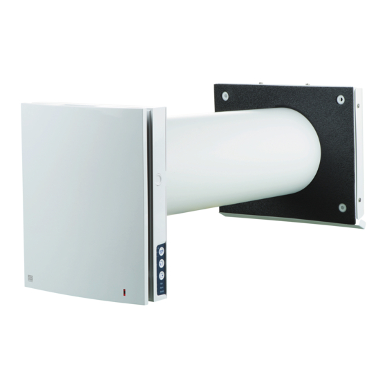
R O O M I E D U A L Product desciption Roomie Dual The ventilator consists of an indoor unit with a decorative front panel and filters, a cartridge, an air duct with air flow separators and an outer ventilation hood. - Page 9 Cartridge design The cartridge is a solid block and cannot be dismantled. The Roomie Dual unit has a cartridge with filters that can be easily removed for maintenance purposes. The socket connector routed from the cartridge is con- nected to the control board in the back part of the indoor unit.
-
Page 10: Mounting And Set-Up
R O O M I E D U A L Mounting and set-up Read the user’s manual prior to moun- ting the unit. Do not block the air duct of the instal- led unit with dust accumulating mate- rials, such as curtains, cloth shutters, etc. - Page 11 3. Stick the delivered cardboard master plate on the Then mark the fastening holes for installation of the sup- indoor wall using a mounting tape. plied dowels and drill the holes to a required depth. The large opening in the master plate must be axially Route the power cable from the ventilator outside aligned with the air duct.
- Page 12 R O O M I E D U A L 5. Fix the back part of the indoor unit on the wall with the Remove the two retaining screws from the left transpar- screws supplied with the mounting kit of the ventilator. ent cover to enable access to the terminals.
- Page 13 7. Install the front part of the indoor unit. 8. Install the sectional air flow separators from the outside. Install a required quantity of the air flow separators in the air duct until it bumps up the cartridge. Mark the last air flow separator to be flush with the air duct face, remove it from the air duct and cut the exces- sive part of the last air flow separator.
-
Page 14: Connection To Power Mains And Control
R O O M I E D U A L Connection to power mains and control Disconnect the unit from power supply prior to any electric installation ope- rations. The rated electrical parameters are stated on the rating plate. Any tampe- ring with the enternal connections is prohibited and will void the warranty. - Page 15 The ventilator design enables connecting any external con- trols with a normally opened contact (NO-contact), such as an external CO sensor, humidity sensor, relay switch, etc. When the contacts NO1 and NO2 close the ventilator switches to high speed. An analogue sensor with output voltage 0-10 V is also com- patible with the unit.
- Page 16 R O O M I E D U A L Wiring diagram for in series connection Master Slave 1 Slave N Power input +12V +12V +12V 100-240 V/50-60 Hz to the next ventilator Wiring diagram for in parallel connection Master Slave 1 Slave N Power input...
- Page 17 Ventilator set-up Prior to operating set up the ventilator using the DIP-switch. It is located on the controller circuit board. To access the Open the rubber plug DIP-switch take off the front panel of the indoor unit and uplift the rubber plug that covers the switch. DIP-switch under the plug Position...
- Page 18 R O O M I E D U A L Humidity sensor setpoint. The humidity sensor measures the extract air humidity. If the extract air humidity is above the set point, the ventilator switches to Speed III. As humidity drops down to the set point, the ventilator changes to pre-set speed after elapsing of the time set on the delay timer.
- Page 19 Unit control The ventilation unit may be operated with the following controls: - infra-red remote controller; - control buttons located on the side wall of the indoor unit. For details, refer to the figure below. Buttons on Remote control the unit casing Speed /OFF Turning unit ON/OFF Speed/off.
- Page 20 R O O M I E D U A L Air flow blocking Press the side tabs to detach the front part of the indoor unit from its back part and close the air duct. Then open the latches and remove the front part of the front panel. Remove the air flow separator by pulling one of the side clamps.
- Page 21 Operation of the ventilation unit with the buttons on the indoor unit The speed selection sequence is as follows: low-medium-high-OFF. All the units integrated in a single network operate according to the speed settings of the Master unit. I: permanent glowing of the lamp indicator indicates operation of the unit with low speed. Blinking of the lamp indicates activation of the Night mode timer.
-
Page 22: Technical Maintenance
R O O M I E D U A L Technical maintenance Maintenance of the ventilator means regular cleaning of the ventilator surfaces of dust and cleaning and replacement of Disconnect the unit from power supply the filters. before any maintenance operations. To access the basic assembly units follow the steps: Turn off the unit using the remote control or the buttons on the indoor unit. - Page 23 3. Pull the cord to remove the cartridge from the air duct. Clean the filters as they get clogged, but not less than once in three months. • After the set filter replacement periodicity (90 days) has expired the Filter indicator starts glowing. •...
-
Page 24: Troubleshooting
R O O M I E D U A L Troubleshooting Problem Possible reasons Troubleshooting Make sure the power supply line is connected cor- No power supply. rectly, otherwise troubleshoot the connection error. When switching on the venti- Turn the ventilator off. Troubleshoot the motor jam lator the fan does not start. -
Page 25: 10. Ce Declaration Of Conformity
1, Mikhaila Kotzubinskogo St., Kiev, 01030, Flexit AS 30.11.2016 Ukraine Type: Single-room ventilators; Roomie One Wifi Roomie Dual Frank Petersen Roomie Dual Wifi Eq 2 Art.no.: 115996, 115999, 116000, 116001 R O O M I E D U A L... - Page 26 R O O M I E D U A L...
- Page 27 R O O M I E D U A L...
- Page 28 Flexit AS, Televeien 15, N-1870 Ørje www.flexit.no...
Need help?
Do you have a question about the Roomie Dual and is the answer not in the manual?
Questions and answers