
Related Manuals for Flexit Roomie One WiFi


Summary of Contents for Flexit Roomie One WiFi
- Page 1 116028EN–04 2019–10 Roomie One WiFi Roomie Dual WiFi Assembly and Operation Instructions ART. NO.: 115996 Heat recovery single-room reversible ventilation unit 116000...
- Page 2 R O O M I E W I F I...
-
Page 3: Table Of Contents
Contents Purpose ....................6 Delivery set....................6 Technical data ..................7 Design and functioning ................. 9 Mounting and set-up ................13 Maintenance ..................36 Troubleshooting ................... 38 Storage and transportation regulations ..........39 CE Declaration of conformity .............. 40 R O O M I E W I F I... -
Page 4: Safety Requirements
The user’s manual consisting of the technical details, reversible ventilation unit with energy regeneration Roomie One WiFi and Roomie Dual WiFi (hereinafter «the to the installation and mounting of the single-room unit»). NB! When a text bears this symbol,... - Page 5 Unit mounting and operation safety precautions • • Disconnect the unit from power mains cables when connecting the unit to prior to any installation operations. power mains. • Do not touch the unit controls with • Do not lay the power cable of the wet hands.
-
Page 6: Purpose
(toxic substances, dust, patho- genic germs). re is outside the temperature range stated in the technical data. Delivery set Quantity Name Roomie One WiFi Roomie Dual WiFi Indoor unit 1 item 1 item Air duct 1 item... -
Page 7: Technical Data
The units are designed for indoor use. Due to on going developments some models can deviate from what is being described in this manual. The unit is rated as a class II electric appliance. Roomie One WiFi Roomie Dual WiFi Speed 17,5 –... - Page 8 R O O M I E W I F I Air duct length Air duct length [mm] Roomie One WiFi Roomie Dual WiFi 240(150*)-500 280-500 * is the minimum air duct length with hood for thinner walls (accessories). Front panel...
-
Page 9: Design And Functioning
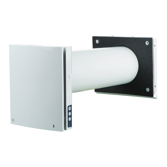
Design and functioning Roomie One WiFi Roomie Dual WiFi The ventilation unit consists of an indoor assembly unit The ventilator consists of an indoor unit with a with a decorative front panel, a cartridge, an air duct with a sound absorbing material and an outer ventilation hood. - Page 10 R O O M I E W I F I Cartridge design Roomie One WiFi Roomie Dual WiFi Filter air stream of dust and foreign objects and prevention of the regenerator contamination. Regenerator Regenerator Provides extract Provides extract air energy...
- Page 11 19.4˚F 70 sec. 62.6˚F +17˚C 14˚F -10˚C Functioning of Roomie One WiFi shutters Shutters are closed. Shutters are open. During the unit operation the shutters open to let the air After the unit shutdown the shutters close within 2 minutes.
- Page 12 R O O M I E W I F I Roomie Dual WiFi operation modes The ventilator has three operation modes: Regeneration. One of the fans of the ventilator operates in extract mode and the other one in supply mode. The fans change their rotation direction every 70 seconds.
-
Page 13: Mounting And Set-Up
3 mm the outer ventilation hood. Distance A, Roomie One WiFi, max 50 mm* Distance A, Roomie Dual WiFi, max 0 mm Adjustment of the air duct length is possible before 0 - 3 mm access must be provided to cut the air duct length after its installation from outside. - Page 14 R O O M I E W I F I 3. Stick the supplied cardboard template on the Mark the openings for dowels from the fastening kit inner wall using a sticker. A big opening must be coaxial with the air duct. Route the power cable from the ventilation unit Use a builder’s level for horizontal alignment of the outside through the marked opening on the mounting...
- Page 15 5. Fix the back part of the indoor unit on the wall with the supplied screws. Remove the two screws from the left transparent cover to enable access to the terminals. 6. Insert the cartridge in the air duct as shown below. Be sure the pointer is directed The pointer must be directed upwards...
- Page 16 R O O M I E W I F I Sound deadening mat Roomie One WiFi Roomie Dual WiFi 9. Insert the sound absorbing layer into the air duct. Roll the sound absorbing layer to match the outside. air duct diameter with the protecting paper layer outside.
-
Page 17: Wiring Diagram
The unit is rated for connection to single-phase AC 100-240 V/ 50-60 Hz power mains. The units shall be installed according to current laws and regulations. The ventilator design enables connecting any external controls with a normally opened contact (NO-contact), such as an external CO sensor, humidity sensor, relay switch, etc. - Page 18 R O O M I E W I F I Ventilation unit set-up Connection of PC/use of DIP switches. You can access the DIP switches and USB socket by removing the front part of the internal part and lifting up the rubber cover. DIP switch and USB socket under the cover...
-
Page 19: Unit Control
The ventilation unit may be operated with the following controls: - infra-red remote controller; - control buttons located on the side wall of the indoor - The application ”Flexit Roomie” from a mobile device (smartphone or tablet). Buttons on Remote control... - Page 20 Alarm indicator for emergency shutdown of the unit. Permanent glowing of the Alarm indicator of the Master unit indicates network. In case of an emergency shutdownof a Roomie One WiFi unit in the network the defective ventilation unit is marked Alarm with the blinking Alarm indicator.
- Page 21 Connection of the ventilation unit to PC: • Start the software application Flexit Roomie at your PC. Ventilation unit set-up • Download and install the software for PC to setup the the DIP switch and USB connector on the control board ventilation unit.
- Page 22 In case of emergency shutdown of any Roomie One WiFi To reset the alarm indication troubleshoot the fan shut- unit in a chain all the Roomie One WiFi units stop. The down and restart the unit using the button on the indoor Roomie Dual WiFi units continue to operate.
- Page 23 Selection of pre-set speed. Low, medium, high speed respectfully. Manual speed setup. To activate the scroll bar check it. Ventilation mode. Roomie One WiFi. The ventilation unit operates in supply or extract mode at set speed. The fan rotation direction depends on PC setting (exhaust mode by default).
- Page 24 (both Master and Slave mode). by means of a mobile device, the remote control or the If any sensor is triggered in a chain of Roomie One WiFi touch buttons on the unit casing. The control signal is ventilation units, all the connected Roomie One WiFi automatically transferred to the connected Slave units.
- Page 25 There are two wireless connection options: Diagram 1 Master with its wireless access point Mobile Slave N Slave N Slave N device Connection of up to 4 Slave units or mobile devices to the Master unit with its own wireless access point.
- Page 26 R O O M I E W I F I If the WiFi router capacity is not enough to connect a wireless access point to connect the other the unit. Router with its wireless access Optionally connection of several Master units to the point network for arranging a zone control is also possible.
- Page 27 Connection of a mobile device to the unit according to the diagram no. 1: • Install the software to your mobile device. • to the diagram No. 1, see page 140. • Activate WiFi in the system menu for the mobile unit and connect to an available network.
- Page 28 R O O M I E W I F I the diagram no. 1: • Start the software at your PC to set up the ventilation unit. • Connect the ventilation unit to PC using a USB to mini USB cable. •...
- Page 29 Check the busy numbers using the installed mobile application. For doing that open the connection menu (1-2), select the connection to the Master (3) and open the Slave status (4). All the busy numbers are highlighted yellow. • Set a free IP address for the Master unit (8). The IP address must be consistent with the current network the diagram no.
- Page 30 R O O M I E W I F I Detection of a free IP address for the Master unit and standard gateway address is as follows: 1. Open the window of the command line: press 5. Detect a free IP address for the Master unit: enter the combination Win+R and enter «cmd»...
- Page 31 Detection of a free IP address for the Slave unit is as follows: 1. PC: Open the window in the command line: press Win + R and enter «cmd» in the «Run» window. Then press Enter. Enter. 3. The «Standard gateway» line indicates the router’s IP address.
- Page 32 R O O M I E W I F I Connection of a mobile device to the unit according to the diagram no. 2: • Install the software to your mobile device. • to the diagram No. 2. • Activate WiFi in the system menu of the mobile device. •...
- Page 33 Operating the ventilation unit through the cloud server The Master unit must be set for the operation mode in compliance with the diagram No. 2. By default the be activated in the following way: • Connect to the Wi-Fi point of the home router in the system menu of the mobile device.
- Page 34 R O O M I E W I F I Entering account: • Enter your login (1) and password (2) on the page of connection through the cloud server. • Press the button (3) to enter the account. Adding new connection: •...
- Page 35 Roomie One WiFi Press the front panel to close the air duct. The fan is stopped. The unit functionality is not changed. To open the air duct pull the front panel through the specially designed recessions. The fan starts operating according to the actual speed setting.
-
Page 36: Maintenance
1. Press the latches on the side of the indoor latches and remove the front part of the front panel. procedures to reassemble. Roomie One WiFi 1. Press the side tabs to release the front part of the indoor unit. - Page 37 2. Remove the socket connector from the control board. Do not remove the socket connector by Roomie One WiFi Roomie Dual WiFi Do not pull the wires! to disconnect the socket. Disconnect the socket Disconnect the socket connector from the control connector from the control board.
-
Page 38: Troubleshooting
R O O M I E W I F I Even regular technical maintenance may not completely prevent dirt accumulation on the regenerator and the fan. • Clean the regenerator regularly to ensure its high heat • Clean the regenerator with a vacuum cleaner at least once in a year. -
Page 39: Storage And Transportation Regulations
Storage and transportation regulations Store the unit in the manufacturer’s original packing box in a dry closed ventilated premise with temperature range from +5 °C to + 40 °C. Storage environment must not contain aggressive vapours and chemical mixtures provoking corrosion, insulation and sealing deformation. -
Page 40: Ce Declaration Of Conformity
EN 55014-2 Member States relating to EN 61000-3-2 electromagnetic compatibility. EN 61000-3-3 Producer: VENTILATION SYSTEMS PrJSC 1, Mikhaila Kotzubinskogo St., Kiev, 01030, Ukraine Flexit AS 30.11.2016 Type: Single-room ventilators; Roomie Dual Frank Petersen Art.no.: 115996, 115999, 116000, 116001... - Page 41 R O O M I E W I F I...
- Page 42 R O O M I E W I F I...
- Page 43 R O O M I E W I F I...
- Page 44 Flexit AS, Televeien 15, N-1870 Ørje...
Need help?
Do you have a question about the Roomie One WiFi and is the answer not in the manual?
Questions and answers